EP0350054A2 - Magnetic recording and reproducing apparatus - Google Patents
Magnetic recording and reproducing apparatus Download PDFInfo
- Publication number
- EP0350054A2 EP0350054A2 EP89112436A EP89112436A EP0350054A2 EP 0350054 A2 EP0350054 A2 EP 0350054A2 EP 89112436 A EP89112436 A EP 89112436A EP 89112436 A EP89112436 A EP 89112436A EP 0350054 A2 EP0350054 A2 EP 0350054A2
- Authority
- EP
- European Patent Office
- Prior art keywords
- tape
- magnetic
- tape guide
- recording
- substrates
- Prior art date
- Legal status (The legal status is an assumption and is not a legal conclusion. Google has not performed a legal analysis and makes no representation as to the accuracy of the status listed.)
- Granted
Links
Images


Classifications
-
- G—PHYSICS
- G11—INFORMATION STORAGE
- G11B—INFORMATION STORAGE BASED ON RELATIVE MOVEMENT BETWEEN RECORD CARRIER AND TRANSDUCER
- G11B15/00—Driving, starting or stopping record carriers of filamentary or web form; Driving both such record carriers and heads; Guiding such record carriers or containers therefor; Control thereof; Control of operating function
- G11B15/60—Guiding record carrier
- G11B15/62—Maintaining desired spacing between record carrier and head
-
- G—PHYSICS
- G11—INFORMATION STORAGE
- G11B—INFORMATION STORAGE BASED ON RELATIVE MOVEMENT BETWEEN RECORD CARRIER AND TRANSDUCER
- G11B5/00—Recording by magnetisation or demagnetisation of a record carrier; Reproducing by magnetic means; Record carriers therefor
- G11B5/48—Disposition or mounting of heads or head supports relative to record carriers ; arrangements of heads, e.g. for scanning the record carrier to increase the relative speed
- G11B5/488—Disposition of heads
- G11B5/4893—Disposition of heads relative to moving tape
Definitions
- the present invention generally relates to magnetic recording and reproducing, and more particularly, to a magnetic recording and reproducing apparatus in which it is required to maintain synchronous relation, for example, between reproducing data and recording data.
- a magnetic head of an induction type is employed, and it is possible to effect the recording and reproducing by the same magnetic head, whereby a high synchronizing accuracy may be readily realized accordingly.
- the magnetic recording and reproducing by the digital system is realized by providing at least one reproducing head and one recording head along the travelling direction of the magnetic tape in that order at a predetermined interval.
- the request for the high density recording as described above has been satisfied by attempting to achieve higher density of the track pitch, and reduction of the shortest recording wavelength. More specifically, in the multi-channel magnetic recording and reproducing apparatus, it is necessary to allocate the channel for each microphone or musical instrument, and furthermore, in the apparatus of the digital system, it is required to lower error rate of the data by dispersing into a plurality of tracks for recording information of one channel, thus inevitably necessitating to provide a large number of tracks for the purpose. As a result, the track pitch becomes, for example, smaller than 100 ⁇ m, which is a marked reduction as compared with that in the conventional apparatuses of the analog system. Moreover, the shortest recording wavelength is now in the order of about 0.6 to 0.7 microns.
- the magnetic tape In order to achieve a high density recording as described above in the multi-channel magnetic recording and reproducing apparatus, it is necessary for the magnetic tape to travel on the order of microns while maintaining the predetermined positional relation with respect to the magnetic head. Furthermore, it is also required to achieve a favorable contact state of the magnetic tape with respect to the magnetic gap of the magnetic head, i.e. to obtain a good "head to tape contact" of the head by reducing spacing loss or azimuth loss which is the conditions specific to the magnetic recording.
- the multi-channel magnetic recording and reproducing apparatus conventionally adopted is arranged as follows.
- the arrangement as disclosed, for example, in the earlier-mentioned Japanese Patent Laid-Open Publication Tokkaisho No. 60-59561 is employed.
- a tape guide is provided within the tape path, thereby to control the magnetic tape.
- an essential object of the present invention is to provide a magnetic recording and reproducing apparatus capable of maintaining synchronous relation between the reproducing data and recording data at high accuracy, with substantial elimination of disadvantages inherent in the conventional apparatuses of this kind.
- Another object of the present invention is to provide a magnetic recording and reproducing apparatus of the above described type which is simple in construction and compact in size.
- a magnetic recording and reproducing apparatus which includes a tape guide unit having a set of spaced two tape guide substrates, a spacer provided between said two tape guide substrates so as to dispose said tape guide substrates through a predetermined interval in approximately a parallel relation to each other, and guide poles for guiding the surface of a magnetic tape, arranged to extend through front portions of said tape guide substrates in a direction generally perpendicular to surfaces of said tape guide substrates, and a plurality of magnetic heads fixed, in a state where their postures are adjusted, to said tape guide unit.
- the magnetic heads are integrally fixed to the tape guide unit in the state adjusted for their postures, no angular adjusting mechanism is required in the respective azimuth direction, hinged direction and tilting direction, for adjusting the postures of the magnetic heads. Accordingly, compact size around the tape guide unit may be achieved for reduction of size of the magnetic recording and reproducing apparatus.
- a magnetic tape recording and reproducing apparatus M1 which generally includes a tape guide unit 1 having an upper substrate 2, a lower substrate 3, a spacer 4 and guide poles 5,6 and 7, and a reproducing head 8 and a recording head 9 fixed to said tape guide unit 1 as described in detail hereinbelow.
- the upper substrate 2 and the lower substrate 3 have a symmetrical shape, and are respectively formed with forwardly projecting portions 2a and 3a at central portions thereof as shown.
- the spacer 4 in an angular column having a trapezoidal cross section is disposed, with the bottom side of the trapezoidal shape directed forwardly i.e. downwardly in Fig. 1.
- the guide poles 5,7 and 6 each of a round rod-like shape are extended through the upper substrate 2 and the lower substrate 3 respectively in front portions at opposite ends and the forwardly projecting portions 2a and 3a of said substrates.
- At least the sliding portions with respect to the magnetic tape 10, in the above guide poles 5,6 and 7 and the upper and lower substrates 2 and 3, should preferably be formed by a material not readily damaging the magnetic tape 10, and yet having a high abrasion resistance.
- the distance between the upper substrate 2 and the lower substrate 3 around the guide poles 5,6 and 7 is so designed that, although generally equal to the width of the magnetic tape 10, it is slightly larger than said width for guiding the magnetic tape 10 travelling in a direction A.
- the interval between said substrates 2 and 3 is maintained at the above distance by the three guide poles 5,6 and 7 and the spacer 4.
- the reproducing head 8 and the recording head 9 are provided along the spacer 4, and the upper and lower substrates 2 and 3.
- the reproducing head 8 and the recording head 9 are arranged in this order along the direction A which is the travelling direction of the magnetic tape 10, with their sliding faces 8a and 9a with respect to the magnetic tape 10 projecting forwardly.
- the tape guide unit 1 for attaching the reproducing head 8 and the recording head 9, the tape guide unit 1 is first assembled in the order of the upper substrate 2, lower substrate 3, spacer 4, and guide poles 5,6 and 7, and then, the reproducing head 8 and the recording head 9 are mounted thereon.
- the reproducing head 8 and the recording head 9 are respectively subjected to adjustments of postures or attitudes thereof, i.e. angular adjustments in the azimuth direction, hinged direction and tilting direction, and also, to adjustments of projection forwardly, i.e. adjustments of projecting amount in the direction of the magnetic tape 10, and further to the positional adjustments in the widthwise and travelling directions of the magnetic tape 10, and thereafter, fixed by a bonding material and screws.
- the reproducing head 8 and the recording head 9 are assembled onto the tape guide unit 1 after effecting various adjustments, it is not necessary to add adjusting mechanisms to the heads 8 and 9 individually, and accordingly, the construction of the apparatus may be simplified for reduction of size.
- the magnetic tape 10 when the magnetic tape 10 is driven, it is guided by the guide poles 5,6 and 7, and the upper and lower substrates 2 and 3, in the state where said magnetic tape is wound around the guide poles 5,6 and 7 by a predetermined angle, and travels in the direction A as it is contacting the sliding surfaces 8a and 9a of the reproducing head 8 and the recording head 9.
- the magnetic tape 10 can move smoothly, with only a small degree of waving being produced, through guiding by the upper and lower substrates 2 and 3.
- FIG. 3 to 5 there is shown a magnetic recording and reproducing apparatus M2 according to a second embodiment of the present invention, in which like parts in Figs. 1 and 2 are designated by like reference numerals for brevity of description.
- the magnetic recording and reproducing apparatus M2 also has a tape guide unit 11 constituted by an upper substrate 12, a lower substrate 13, a spacer 4 and guide poles 5,6 and 7.
- the upper substrate 12 and the lower substrate 13 are not in a symmetrical configuration, but in the upper substrate 12, its under surface around the inserted portion of the central guide pole 6 slightly protrudes downwardly with respect to the undersurfaces thereof around the inserted portions of the guide pole 5 at a supply side and of the guide pole 7 at the take-up side, while, in the lower substrate 13, the upper surfaces thereof around the inserted portions of the guide pole 5 at the supply side and of the guide pole 7 the take-up side protrude upwardly to a certain extent, as compared with its uppersurfaces around the inserted portion of the central guide pole 6.
- the undersurface thereof around the inserted portion of the central guide pole 6 serves as a tape guide face 12b
- the upper surfaces thereof around the inserted portions of the guide pole 5 at the supply side and of the guide pole 7 at the take-up side respectively serve as the tape guide faces 13b and 13c.
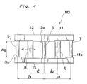
- a tape guide width Wg (Fig. 4) is designed to be slightly smaller than a tape width Wt(Fig. 5) of the magnetic tape 10.
- the distance between an axis of the central guide pole 6 and magnetic gap of the reproducing head 8 on the tape path is represented by l1, and the distance between an axis of the central guide pole 6 and magnetic gap of the recording head 9 on the tape path is denoted by l2.
- the distance between the axis of the central guide pole 6 and that of the guide pole 5 at the supply side on the tape path is indicated by l3, while the distance between the axis of the central guide pole 6 and that of the guide pole 7 at the take-up side on the tape path is represented by l4.
- the extent for setting the tape guide width Wg smaller than the tape width Wt varies according to the tape width Wt, distances l3 and l4, ad the winding angle of the magnetic tape 10 around the respective guide poles 5,6 and 7.
- the distance l3 or l4 is approximately 20mm
- the winding angle of the magnetic tape 10 around the guide poles 5,6 and 7 is about 200, it is proper to set the tape guide width Wg smaller than the tape width Wt by approximately 10 to 60 ⁇ m.
- the edge portions in the widthwise direction of the magnetic tape 10 travelling in the direction A as it is guided by the tape guide unit 11 are arranged to alternately slide on the tape guide faces in such an order as the lower tape guide face 13b, the upper tape guide face 12b, and then, the lower tape guide face 13c.
- travelling of the magnetic tape 10 through a positional relation with respect to the magnetic heads 8 and 9 on the order of microns becomes possible, since said magnetic tape is properly guided by the tape guide face 12b of the upper substrate 12, and the tape guide faces 13b and 13c of the lower substrate 13.
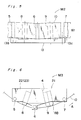
- the magnetic tape 10 travels between the guide poles 5 and 6 as it is inclined downwards towards the guide pole 6 at an angle represented by tan ⁇ 1 ((Wt-Wg)/l3), and between the guide poles 6 and 7 as it is inclined upwards towards said guide pole 7 at an angle represented by tan ⁇ 1 ((Wt-Wg)/l4). Accordingly, in the arrangement of the second embodiment, it is necessary to mount the reproducing head 8 and the recording head 9 onto the tape guide unit 11 by correcting the above angles in order to eliminate the azimuth error.
- the height of the travelling magnetic tape 10 becomes low by a degree as represented by (Wt-Wg) ⁇ (l3-l1)/l3 at the magnetic gap portion of the reproducing head 8, and similarly, by a degree as represented by (Wt-Wg) ⁇ (l4-l2)/l4 at the magnetic gap portion of the recording head 9. Therefore, it is required to correct the heights of the both heads by the above degrees.
- setting for the distance between the magnetic gaps and attitudes of the reproducing head 8 and the recording head 9 during assembling of such heads onto the tape guide unit 11, may be readily effected by employing jigs for the purpose (not shown), and by removing such jigs after completion of fixing of the both heads 8 and 9, and thus, the magnetic head unit in which the tape guide unit 11 and the both heads 8 and 9 are combined into one unit may be obtained.
- the distance between the heads and "head to tape contact" are compensated for, and, a compact magnetic recording and reproducing apparatus having a high travelling accuracy may be provided.
- FIG. 6 there is shown a magnetic recording and reproducing apparatus M3 according to a third embodiment of the present invention, in which like parts in Figs. 1 to 5 are also designated by like reference numerals for brevity of description.
- the magnetic recording and reproducing apparatus M3 includes a tape guide unit 21 having the upper substrate 22 and lower substrate 23 (not particularly shown), spacer 4, and guide poles 5,6 and 7, and said upper and lower substrates 22 and 23 have the tape guide faces alternately provided in the similar manner as described in the second embodiment, although not particularly shown here, with the reproducing head 8 and recording head 9 being provided along said substrates in that order in the travelling direction A for the magnetic tape 10.
- another reproducing head 8B is provided to be in a set with said recording head 9 as shown, and thus, the reproducing head 8, recording head 9 and reproducing head 8B are disposed in that order along the travelling direction of the magnetic head 10.
- the above arrangement may further be modified, for example, to constitute the tape guide unit by providing four guide poles so that one of each of the magnetic heads 8,9 and 8B may be disposed between each set of two guide poles, although not particularly shown.
- the recording head 9 and the reproducing head 8B provided in a set as a single magnetic head in the disposition, and to install them in the positional relation as described above.
- a tape guide unit having n pieces of guide poles is prepared, with each magnetic head being disposed between each set of guide poles.
- the magnetic tape 10 which travels as it is guided by the tape guide unit is guided at its edges in the widthwise direction thereof, by the tape guide faces alternately provided on the upper and lower substrates as described earlier.
- the magnetic recording and reproducing apparatus is constituted by the tape guide unit including the set of spaced two tape guide substrates, the spacer provided between said tape guide substrates so as to dispose the two tape guide substrates through a predetermined distance in approximately a parallel relation to each other, and the guide poles for guiding the surface of a magnetic tape, arranged to extend through the front portions of said tape guide substrates in a direction generally perpendicular to the surfaces of said tape guide substrates, and a plurality of magnetic heads fixed, in a state where their postures are adjusted, to said tape guide unit.
- the adjusting mechanism for the attitude of the magnetic head may be omitted for compact size around the tape guide unit, thereby making it possible to reduce the size of the magnetic recording and reproducing apparatus on the whole.
Landscapes
- Adjustment Of The Magnetic Head Position Track Following On Tapes (AREA)
Abstract
Description
- The present invention generally relates to magnetic recording and reproducing, and more particularly, to a magnetic recording and reproducing apparatus in which it is required to maintain synchronous relation, for example, between reproducing data and recording data.
- Recently, in sites for recording music and the like, there have been widely adopted recording systems which employ many microphones to correspond to individual musical instruments, or those in which musical instruments are individually played without playing all the musical instruments simultaneously for recording at each playing. For the recording systems as referred to above, there has been generally employed a multi-channel magnetic recording and reproducing apparatus in which channels are individually allocated to respective microphones and musical instruments for recording, and in a recent trend, the recording system of said magnetic recording and reproducing apparatus is being shifted from the analog system to the digital system.
- In the recording by the multi-channel magnetic recording and reproducing apparatus as described above, even in the case where the playing by the respective musical instruments has been simultaneously recorded, it it seldom to complete recording by the recording at one time, but normally, so-called punch in/out is effected in which the predetermined performance of a specific channel is repeatedly recorded until satisfaction is achieved. Meanwhile, in the case where a simultaneous recording is not effected, a synchronous recording is made in which playing by another musical instrument is recorded in a different channel, while the sound of the channel recorded earlier is being reproduced. In the multi-channel magnetic recording and reproducing apparatus for effecting the function as described above, it is an essential function to maintain synchronization among the respective channels on the magnetic tape at high accuracy.
- In the multi-channel magnetic recording and reproducing apparatus of the analog type, a magnetic head of an induction type is employed, and it is possible to effect the recording and reproducing by the same magnetic head, whereby a high synchronizing accuracy may be readily realized accordingly.
- On the contrary, in the multi-channel magnetic recording and reproducing apparatus of the digital system, it is so arranged that a delay is produced between the time at which date is inputted into a circuit or it is outputted from the circuit and the time at which data is recorded on a magnetic tape by the magnetic head or it is reproduced from the magnetic tape. Therefore, in the recording and reproducing by the single head, for example, the punch in/out referred to earlier can not be properly effected. Accordingly, the magnetic recording and reproducing by the digital system is realized by providing at least one reproducing head and one recording head along the travelling direction of the magnetic tape in that order at a predetermined interval.
- Moreover, in the multi-channel magnetic recording and reproducing apparatus of the digital system as described above, it is necessary to control a moving distance of the magnetic tape between the preceding reproducing head and the recording head, i.e. the distance on a tape path in a range permissible by a digital signal processing format. A mechanical adjusting mechanism for the above purpose is disclosed, for example, in Japanese Patent Laid-Open Publication Tokkaisho No. 60-59561.
- Meanwhile, in the magnetic recording and reproducing apparatuses in general, high density recording with high reliability, and consequent reduction in the consumption of recording medium and smaller size of the apparatus, etc. are required.
- The request for the high density recording as described above has been satisfied by attempting to achieve higher density of the track pitch, and reduction of the shortest recording wavelength. More specifically, in the multi-channel magnetic recording and reproducing apparatus, it is necessary to allocate the channel for each microphone or musical instrument, and furthermore, in the apparatus of the digital system, it is required to lower error rate of the data by dispersing into a plurality of tracks for recording information of one channel, thus inevitably necessitating to provide a large number of tracks for the purpose. As a result, the track pitch becomes, for example, smaller than 100µm, which is a marked reduction as compared with that in the conventional apparatuses of the analog system. Moreover, the shortest recording wavelength is now in the order of about 0.6 to 0.7 microns.
- In order to achieve a high density recording as described above in the multi-channel magnetic recording and reproducing apparatus, it is necessary for the magnetic tape to travel on the order of microns while maintaining the predetermined positional relation with respect to the magnetic head. Furthermore, it is also required to achieve a favorable contact state of the magnetic tape with respect to the magnetic gap of the magnetic head, i.e. to obtain a good "head to tape contact" of the head by reducing spacing loss or azimuth loss which is the conditions specific to the magnetic recording.
- As described above, the conditions required for the multi-channel magnetic recording and reproducing apparatus of the digital system are as follows.
- (1) The distance on the tape path between the preceding reproducing head and the recording head should be accurately controlled.
- (2) With respect to the travelling of the magnetic tape, variation in a widthwise direction should be controlled at an accuracy on the order of microns.
- 3) A favorable "head to tape contact" should be maintained.
- For satisfying the conditions as described above, the multi-channel magnetic recording and reproducing apparatus conventionally adopted is arranged as follows.
- In order to accurately control the distance on the tape path between the preceding reproducing head and the recording head, the arrangement as disclosed, for example, in the earlier-mentioned Japanese Patent Laid-Open Publication Tokkaisho No. 60-59561 is employed. Moreover, for causing the magnetic tape to accurately travel on the order of microns, a tape guide is provided within the tape path, thereby to control the magnetic tape. Furthermore, for maintaining a favorable "head touch", it is necessary to adjust the attitudes or postures, and height of the magnetic heads in the azimuth direction, hinged direction and tilting direction, etc., with respect to the tape travelling face, and the individual magnetic heads are mounted through suspension mechanisms having the adjusting functions as stated above.
- However, in the conventional arrangement as described above, since various adjusting mechanisms must be provided around the magnetic heads for recording and reproduction and the tape guide, size reduction in the vicinity of the magnetic heads and the tape guide is undesirably restricted, thus obstracting achievement of compact size of the apparatus on the whole. Particularly, in the magnetic recording and reproducing apparatus which employes the magnetic tape, although it is essential to shift from the open reel type to the cassette type from the viewpoint of operation , the difficulty in the size reduction around the magnetic head and the tape guide presents a large obstruction for the shifting into the cassette construction of the magnetic tape.
- Accordingly, an essential object of the present invention is to provide a magnetic recording and reproducing apparatus capable of maintaining synchronous relation between the reproducing data and recording data at high accuracy, with substantial elimination of disadvantages inherent in the conventional apparatuses of this kind.
- Another object of the present invention is to provide a magnetic recording and reproducing apparatus of the above described type which is simple in construction and compact in size.
- In accomplishing these and other objects, according to one preferred embodiment of the present invention, there is provided a magnetic recording and reproducing apparatus which includes a tape guide unit having a set of spaced two tape guide substrates, a spacer provided between said two tape guide substrates so as to dispose said tape guide substrates through a predetermined interval in approximately a parallel relation to each other, and guide poles for guiding the surface of a magnetic tape, arranged to extend through front portions of said tape guide substrates in a direction generally perpendicular to surfaces of said tape guide substrates, and a plurality of magnetic heads fixed, in a state where their postures are adjusted, to said tape guide unit.
- By the arrangement according to the present invention as described above, since the magnetic heads are integrally fixed to the tape guide unit in the state adjusted for their postures, no angular adjusting mechanism is required in the respective azimuth direction, hinged direction and tilting direction, for adjusting the postures of the magnetic heads. Accordingly, compact size around the tape guide unit may be achieved for reduction of size of the magnetic recording and reproducing apparatus.
- These and other objects and feature of the present invention will become apparent from the following description taken in conjunction with the preferred embodiment thereof with reference to the accompanying drawings, in which;
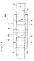
- Fig. 1 is a top plan view showing a magnetic recording and reproducing apparatus M1 according to one preferred embodiment of the present invention which includes a tape guide unit, and reproducing and recording heads provided thereon,
- Fig. 2 is a front elevational view of the magnetic recording and reproducing apparatus M1 of Fig.1,
- Fig. 3 is a front elevational view of a magnetic recording and reproducing apparatus M2 according to a second embodiment of the present invention, showing the state in which the magnetic tape is guided by the tape guide unit,
- Fig. 4 is also a front elevational view of the apparatus M2 of Fig. 3, which particularly shows positional relation of the tape guide unit, and reproducing and recording heads provided thereon.
- Fig. 5 is a diagram explanatory of the state of travelling of the magnetic tape in the apparatus M2, and
- Fig. 6 is a top plan view of a magnetic recording and reproducing apparatus M3 according to a third embodiment of the present invention.
- Before the description of the present invention proceeds, it is to be noted that like parts are designated by like reference numerals throughout the accompanying drawings.
- Referring now to the drawings, there is shown in Figs. 1 and 2, a magnetic tape recording and reproducing apparatus M1 according to one preferred embodiment of the present invention, which generally includes a
tape guide unit 1 having anupper substrate 2, alower substrate 3, aspacer 4 andguide poles head 8 and arecording head 9 fixed to saidtape guide unit 1 as described in detail hereinbelow. - As shown in Figs. 1 and 2, the
upper substrate 2 and thelower substrate 3 have a symmetrical shape, and are respectively formed with forwardly projectingportions upper substrate 2 and thelower substrate 3, thespacer 4 in an angular column having a trapezoidal cross section is disposed, with the bottom side of the trapezoidal shape directed forwardly i.e. downwardly in Fig. 1. - Moreover, the
guide poles upper substrate 2 and thelower substrate 3 respectively in front portions at opposite ends and the forwardly projectingportions magnetic tape 10, in theabove guide poles lower substrates magnetic tape 10, and yet having a high abrasion resistance. The distance between theupper substrate 2 and thelower substrate 3 around theguide poles magnetic tape 10, it is slightly larger than said width for guiding themagnetic tape 10 travelling in a direction A. Thus, the interval between saidsubstrates guide poles spacer 4. - Meanwhile, on one side face and the other side face of the
spacer 4, inclined towards the bottom side of the trapezoidal cross section in thetape guide unit 1, the reproducinghead 8 and therecording head 9 are provided along thespacer 4, and the upper andlower substrates head 8 and therecording head 9 are arranged in this order along the direction A which is the travelling direction of themagnetic tape 10, with their slidingfaces magnetic tape 10 projecting forwardly. - In the above construction, for attaching the reproducing
head 8 and therecording head 9, thetape guide unit 1 is first assembled in the order of theupper substrate 2,lower substrate 3,spacer 4, andguide poles head 8 and therecording head 9 are mounted thereon. In order to satisfy the track pattern of a predetermined track of themagnetic tape 10 and also to achieved a favorable "head to tape contact", the reproducinghead 8 and therecording head 9 are respectively subjected to adjustments of postures or attitudes thereof, i.e. angular adjustments in the azimuth direction, hinged direction and tilting direction, and also, to adjustments of projection forwardly, i.e. adjustments of projecting amount in the direction of themagnetic tape 10, and further to the positional adjustments in the widthwise and travelling directions of themagnetic tape 10, and thereafter, fixed by a bonding material and screws. - As described so far, since the reproducing
head 8 and therecording head 9 are assembled onto thetape guide unit 1 after effecting various adjustments, it is not necessary to add adjusting mechanisms to theheads - On the other hand, when the
magnetic tape 10 is driven, it is guided by theguide poles lower substrates guide poles sliding surfaces head 8 and therecording head 9. In this case, themagnetic tape 10 can move smoothly, with only a small degree of waving being produced, through guiding by the upper andlower substrates - Referring further to Figs. 3 to 5, there is shown a magnetic recording and reproducing apparatus M2 according to a second embodiment of the present invention, in which like parts in Figs. 1 and 2 are designated by like reference numerals for brevity of description.
- As shown in Figs. 3 and 4, the magnetic recording and reproducing apparatus M2 also has a
tape guide unit 11 constituted by anupper substrate 12, alower substrate 13, aspacer 4 andguide poles - In this embodiment, however, the
upper substrate 12 and thelower substrate 13 are not in a symmetrical configuration, but in theupper substrate 12, its under surface around the inserted portion of thecentral guide pole 6 slightly protrudes downwardly with respect to the undersurfaces thereof around the inserted portions of theguide pole 5 at a supply side and of theguide pole 7 at the take-up side, while, in thelower substrate 13, the upper surfaces thereof around the inserted portions of theguide pole 5 at the supply side and of theguide pole 7 the take-up side protrude upwardly to a certain extent, as compared with its uppersurfaces around the inserted portion of thecentral guide pole 6. - Accordingly, in the
upper substrate 12, the undersurface thereof around the inserted portion of thecentral guide pole 6 serves as atape guide face 12b, and in thelower substrate 13, the upper surfaces thereof around the inserted portions of theguide pole 5 at the supply side and of theguide pole 7 at the take-up side respectively serve as the tape guide faces 13b and 13c. - The interval between the
tape guide face 12b in the aboveupper substrate 12 and the tape guide faces 13b and 13c in thelower substrate 13, i.e. a tape guide width Wg (Fig. 4) is designed to be slightly smaller than a tape width Wt(Fig. 5) of themagnetic tape 10. The distance between an axis of thecentral guide pole 6 and magnetic gap of the reproducinghead 8 on the tape path is represented by ℓ1, and the distance between an axis of thecentral guide pole 6 and magnetic gap of therecording head 9 on the tape path is denoted by ℓ2. The distance between the axis of thecentral guide pole 6 and that of theguide pole 5 at the supply side on the tape path is indicated by ℓ3, while the distance between the axis of thecentral guide pole 6 and that of theguide pole 7 at the take-up side on the tape path is represented by ℓ4. - The extent for setting the tape guide width Wg smaller than the tape width Wt varies according to the tape width Wt, distances ℓ3 and ℓ4, ad the winding angle of the
magnetic tape 10 around therespective guide poles magnetic tape 10 around theguide poles - In the above arrangement of Fig. 4, favorable travelling characteristics of the magnetic tape may be achieved.
- More specifically, in the arrangement of the first embodiment of Figs. 1 and 2 described earlier, scattering is present in the interval between the
upper substrate 2 and thelower substrate 3, and moreover, scattering of about ±10µm is also present in the width of themagnetic tape 10. Therefore, in the worst case, there is a possibility that the interval between theupper substrate 2 and thelower substrate 3 becomes larger than the tape width by several tens of microns. In such a case, it is difficult to cause themagnetic tape 10 to travel by maintaining the positional relation on the order of microns with respect to the respectivemagnetic heads - Meanwhile, according to the apparatus M2 of the second embodiment in Figs. 3 to 5, the edge portions in the widthwise direction of the
magnetic tape 10 travelling in the direction A as it is guided by thetape guide unit 11 are arranged to alternately slide on the tape guide faces in such an order as the lowertape guide face 13b, the uppertape guide face 12b, and then, the lowertape guide face 13c. Thus, travelling of themagnetic tape 10 through a positional relation with respect to themagnetic heads tape guide face 12b of theupper substrate 12, and the tape guide faces 13b and 13c of thelower substrate 13. - It should be noted here that, in the above case, as shown in Fig. 5, the
magnetic tape 10 travels between theguide poles guide pole 6 at an angle represented by
tan⁻¹ ((Wt-Wg)/ℓ3),
and between theguide poles guide pole 7 at an angle represented by
tan⁻¹ ((Wt-Wg)/ℓ4).
Accordingly, in the arrangement of the second embodiment, it is necessary to mount the reproducinghead 8 and therecording head 9 onto thetape guide unit 11 by correcting the above angles in order to eliminate the azimuth error. - It should also be noted that in the arrangement of this embodiment, the height of the travelling
magnetic tape 10 becomes low by a degree as represented by
(Wt-Wg) × (ℓ3-ℓ1)/ℓ3
at the magnetic gap portion of the reproducinghead 8, and similarly, by a degree as represented by
(Wt-Wg) × (ℓ4-ℓ2)/ℓ4
at the magnetic gap portion of therecording head 9. Therefore, it is required to correct the heights of the both heads by the above degrees. - Although the corrections as described above are necessary in the second embodiment, since it is possible to effect the travelling of the
magnetic tape 10 at a high accuracy as stated earlier, the disadvantage which requires the corrections may be fully compensated for. - Moreover, setting for the distance between the magnetic gaps and attitudes of the reproducing
head 8 and therecording head 9 during assembling of such heads onto thetape guide unit 11, may be readily effected by employing jigs for the purpose (not shown), and by removing such jigs after completion of fixing of the bothheads tape guide unit 11 and the bothheads - Referring further to Fig. 6, there is shown a magnetic recording and reproducing apparatus M3 according to a third embodiment of the present invention, in which like parts in Figs. 1 to 5 are also designated by like reference numerals for brevity of description.
- In Fig. 6, the magnetic recording and reproducing apparatus M3 includes a
tape guide unit 21 having theupper substrate 22 and lower substrate 23 (not particularly shown),spacer 4, and guidepoles lower substrates head 8 andrecording head 9 being provided along said substrates in that order in the travelling direction A for themagnetic tape 10. In this embodiment, however, in position adjacent to therecording head 9, another reproducinghead 8B is provided to be in a set with saidrecording head 9 as shown, and thus, the reproducinghead 8,recording head 9 and reproducinghead 8B are disposed in that order along the travelling direction of themagnetic head 10. By the above arrangement, it becomes possible to effect the reproduction immediately after recording on themagnetic tape 10, i.e. to effect so-called "read after write". - It is to be noted here that, the above arrangement may further be modified, for example, to constitute the tape guide unit by providing four guide poles so that one of each of the
magnetic heads recording head 9 and the reproducinghead 8B provided in a set, as a single magnetic head in the disposition, and to install them in the positional relation as described above. - Accordingly, in the case where the magnetic heads in a set provided side by side are regarded as one magnetic head, and magnetic heads, seemingly in (n-1) pieces are to be mounted, a tape guide unit having n pieces of guide poles is prepared, with each magnetic head being disposed between each set of guide poles. In the above case, it may be so arranged that the
magnetic tape 10 which travels as it is guided by the tape guide unit is guided at its edges in the widthwise direction thereof, by the tape guide faces alternately provided on the upper and lower substrates as described earlier. - As is clear from the foregoing description, the magnetic recording and reproducing apparatus according to the present invention is constituted by the tape guide unit including the set of spaced two tape guide substrates, the spacer provided between said tape guide substrates so as to dispose the two tape guide substrates through a predetermined distance in approximately a parallel relation to each other, and the guide poles for guiding the surface of a magnetic tape, arranged to extend through the front portions of said tape guide substrates in a direction generally perpendicular to the surfaces of said tape guide substrates, and a plurality of magnetic heads fixed, in a state where their postures are adjusted, to said tape guide unit.
- Therefore, the adjusting mechanism for the attitude of the magnetic head may be omitted for compact size around the tape guide unit, thereby making it possible to reduce the size of the magnetic recording and reproducing apparatus on the whole.
- Although the present invention has been fully described by way of example with reference to the accompanying drawings, it is to be noted here that various changes and modifications will be apparent to those skilled in art. Therefore, unless otherwise such changes and modifications depart from the scope of the present invention, they should be construed as included therein.
Claims (4)
Applications Claiming Priority (2)
| Application Number | Priority Date | Filing Date | Title |
|---|---|---|---|
| JP171305/88 | 1988-07-08 | ||
| JP63171305A JP2678019B2 (en) | 1988-07-08 | 1988-07-08 | Magnetic recording / reproducing device |
Publications (3)
| Publication Number | Publication Date |
|---|---|
| EP0350054A2 true EP0350054A2 (en) | 1990-01-10 |
| EP0350054A3 EP0350054A3 (en) | 1990-09-05 |
| EP0350054B1 EP0350054B1 (en) | 1995-02-01 |
Family
ID=15920816
Family Applications (1)
| Application Number | Title | Priority Date | Filing Date |
|---|---|---|---|
| EP89112436A Expired - Lifetime EP0350054B1 (en) | 1988-07-08 | 1989-07-07 | Magnetic recording and reproducing apparatus |
Country Status (4)
| Country | Link |
|---|---|
| US (1) | US5016132A (en) |
| EP (1) | EP0350054B1 (en) |
| JP (1) | JP2678019B2 (en) |
| DE (1) | DE68920921T2 (en) |
Cited By (3)
| Publication number | Priority date | Publication date | Assignee | Title |
|---|---|---|---|---|
| EP0532012A2 (en) * | 1991-09-11 | 1993-03-17 | Matsushita Electric Industrial Co., Ltd. | Magnetic head assembly |
| EP0652557A2 (en) * | 1993-11-05 | 1995-05-10 | Philips Patentverwaltung GmbH | Magnetic tape cassette apparatus with a tape guide for a magnetic tape near the magnetic gaps of a magnetic head of the apparatus |
| EP2009631A1 (en) * | 2007-06-29 | 2008-12-31 | Quantum Corporation | Tape guider for limiting lateral tape motion |
Families Citing this family (5)
| Publication number | Priority date | Publication date | Assignee | Title |
|---|---|---|---|---|
| EP0385359B1 (en) * | 1989-02-28 | 1996-01-10 | Canon Denshi Kabushiki Kaisha | Magnetic head |
| JPH04216354A (en) * | 1990-02-16 | 1992-08-06 | Pioneer Electron Corp | Magnetic head device |
| JPH05120770A (en) * | 1991-10-25 | 1993-05-18 | Alps Electric Co Ltd | Mechanism for supporting magnetic head |
| US5357390A (en) * | 1991-12-11 | 1994-10-18 | U.S. Philips Corporation | Magnetic tape with a cylindrical magnetic head housing |
| US6606219B2 (en) | 2001-02-28 | 2003-08-12 | Lafe Technology Limited | Magnetic tape head including a transducer cluster and a block fixed to a u-shaped frame having a ridge |
Citations (8)
| Publication number | Priority date | Publication date | Assignee | Title |
|---|---|---|---|---|
| US3710037A (en) * | 1971-02-04 | 1973-01-09 | United Res Labor | Removable magnetic head assembly with lifter fingers |
| US3756610A (en) * | 1971-01-08 | 1973-09-04 | Cogar Corp | Tape travel guiding apparatus |
| US3893188A (en) * | 1974-06-05 | 1975-07-01 | William M Shoemaker | Multichannel magnetic head unit |
| US4158868A (en) * | 1978-02-07 | 1979-06-19 | International Tapetronics Corporation | Universally adjustable head support for tape deck |
| GB2070841A (en) * | 1980-02-28 | 1981-09-09 | Oxby D V | Recording techniques |
| EP0097077A1 (en) * | 1982-06-11 | 1983-12-28 | MONDIAL ELECTRONIQUE, Société dite: | Tape deck |
| JPS6045967A (en) * | 1984-06-12 | 1985-03-12 | Matsushita Electric Ind Co Ltd | Magnetic recording and reproducing device |
| EP0323188A2 (en) * | 1987-12-25 | 1989-07-05 | Sharp Kabushiki Kaisha | Magnetic recording and reproducing head unit |
Family Cites Families (11)
| Publication number | Priority date | Publication date | Assignee | Title |
|---|---|---|---|---|
| US3091764A (en) * | 1956-12-21 | 1963-05-28 | Jules H Sreb | Anticollision system for ships and planes |
| NL245367A (en) * | 1959-11-14 | |||
| JPS5839556Y2 (en) * | 1979-01-18 | 1983-09-06 | ナカミチ株式会社 | pad abutting device |
| NL8200175A (en) * | 1981-04-13 | 1982-11-01 | Philips Nv | MAGNETIC BAND TAPE DEVICE AND MAGNETIC UNIT APPLICABLE TO SUCH A DEVICE. |
| JPS58140514U (en) * | 1982-03-10 | 1983-09-21 | 株式会社日立製作所 | Tape position regulating device |
| DE8222016U1 (en) * | 1982-08-04 | 1983-02-10 | Basf Ag, 6700 Ludwigshafen | ADJUSTING DEVICE FOR GUIDE ELEMENTS AND MAGNETIC TAPE CASSETTE WITH SUCH ADJUSTING DEVICE |
| JPS5938915A (en) * | 1982-08-26 | 1984-03-03 | Matsushita Electric Ind Co Ltd | Magnetic head |
| US4646186A (en) * | 1982-09-14 | 1987-02-24 | Alps Electric Co., Ltd. | Cassette tape recorder with plural tape guide structure |
| JPS6059561A (en) * | 1983-09-12 | 1985-04-05 | Matsushita Electric Ind Co Ltd | Magnetic recording and reproducing device |
| JPS61289569A (en) * | 1985-06-17 | 1986-12-19 | Sharp Corp | Magnetic tape travelling device |
| JPH01155567A (en) * | 1987-12-11 | 1989-06-19 | Sharp Corp | Digital recording and reproducing device |
-
1988
- 1988-07-08 JP JP63171305A patent/JP2678019B2/en not_active Expired - Fee Related
-
1989
- 1989-07-07 US US07/376,645 patent/US5016132A/en not_active Expired - Lifetime
- 1989-07-07 EP EP89112436A patent/EP0350054B1/en not_active Expired - Lifetime
- 1989-07-07 DE DE68920921T patent/DE68920921T2/en not_active Expired - Lifetime
Patent Citations (8)
| Publication number | Priority date | Publication date | Assignee | Title |
|---|---|---|---|---|
| US3756610A (en) * | 1971-01-08 | 1973-09-04 | Cogar Corp | Tape travel guiding apparatus |
| US3710037A (en) * | 1971-02-04 | 1973-01-09 | United Res Labor | Removable magnetic head assembly with lifter fingers |
| US3893188A (en) * | 1974-06-05 | 1975-07-01 | William M Shoemaker | Multichannel magnetic head unit |
| US4158868A (en) * | 1978-02-07 | 1979-06-19 | International Tapetronics Corporation | Universally adjustable head support for tape deck |
| GB2070841A (en) * | 1980-02-28 | 1981-09-09 | Oxby D V | Recording techniques |
| EP0097077A1 (en) * | 1982-06-11 | 1983-12-28 | MONDIAL ELECTRONIQUE, Société dite: | Tape deck |
| JPS6045967A (en) * | 1984-06-12 | 1985-03-12 | Matsushita Electric Ind Co Ltd | Magnetic recording and reproducing device |
| EP0323188A2 (en) * | 1987-12-25 | 1989-07-05 | Sharp Kabushiki Kaisha | Magnetic recording and reproducing head unit |
Non-Patent Citations (1)
| Title |
|---|
| PATENT ABSTRACTS OF JAPAN vol. 9, no. 170 (P-373)(1893) 16 July 1985, & JP-A-60 45967 (MATSUSHITA DENKI SANGYO) 12 March 1985, * |
Cited By (8)
| Publication number | Priority date | Publication date | Assignee | Title |
|---|---|---|---|---|
| EP0532012A2 (en) * | 1991-09-11 | 1993-03-17 | Matsushita Electric Industrial Co., Ltd. | Magnetic head assembly |
| EP0532012A3 (en) * | 1991-09-11 | 1994-08-10 | Matsushita Electric Ind Co Ltd | Magnetic head assembly |
| US5638238A (en) * | 1991-09-11 | 1997-06-10 | Matsushita Electric Industrial Co., Ltd. | Magnetic head device with magnetic tape guides |
| EP0769779A3 (en) * | 1991-09-11 | 1998-04-22 | Matsushita Electric Industrial Co., Ltd. | Magnetic head assembly |
| EP0652557A2 (en) * | 1993-11-05 | 1995-05-10 | Philips Patentverwaltung GmbH | Magnetic tape cassette apparatus with a tape guide for a magnetic tape near the magnetic gaps of a magnetic head of the apparatus |
| EP0652557A3 (en) * | 1993-11-05 | 1995-07-26 | Philips Patentverwaltung | Magnetic tape cassette apparatus with a tape guide for a magnetic tape near the magnetic gaps of a magnetic head of the apparatus. |
| US5610787A (en) * | 1993-11-05 | 1997-03-11 | U.S. Philips Corporation | Magnetic tape apparatus with tape edge guides for reduced tape edge wear |
| EP2009631A1 (en) * | 2007-06-29 | 2008-12-31 | Quantum Corporation | Tape guider for limiting lateral tape motion |
Also Published As
| Publication number | Publication date |
|---|---|
| EP0350054B1 (en) | 1995-02-01 |
| EP0350054A3 (en) | 1990-09-05 |
| JP2678019B2 (en) | 1997-11-17 |
| DE68920921T2 (en) | 1995-08-17 |
| JPH0221453A (en) | 1990-01-24 |
| US5016132A (en) | 1991-05-14 |
| DE68920921D1 (en) | 1995-03-16 |
Similar Documents
| Publication | Publication Date | Title |
|---|---|---|
| US5452165A (en) | Close packed magnetic head linear array | |
| US7529060B2 (en) | Read and write head element arrangement | |
| US6768608B2 (en) | Multi-channel magnetic tape system having optical tracking servo | |
| US6005737A (en) | Magnetic tape drive having improved servo control | |
| EP0067061A1 (en) | Azimuthal magnetic recording and reproducing apparatus | |
| US20030099057A1 (en) | Hybrid servopositioning systems | |
| US7075752B2 (en) | Magnetic head apparatus, magnetic reproducing method, and magnetic reproducing apparatus in linear tape system | |
| US7649707B2 (en) | Auto-servo tape system and associated recording head | |
| US6172837B1 (en) | Postponable servo code selection | |
| EP0350054B1 (en) | Magnetic recording and reproducing apparatus | |
| KR880001697B1 (en) | Rotatable head assembly | |
| US4953161A (en) | Magnetic head tracking device using plural gaps | |
| US5345341A (en) | Method of manufacturing a replicated magnetic reproducing medium, such as a magnetic-tape cassette provided with a music recording, and magnetic replication head and replication arrangement for use in the method | |
| JPH07282427A (en) | Magnetic head device and magnetic tape traveling system | |
| US4156258A (en) | Head positioning device for multi-track tape recorders | |
| EP0505983A3 (en) | Magnetic head and a digital recording magnetic head | |
| JPS61120314A (en) | Thin film magnetic head | |
| EP0561453B1 (en) | Method of manufacturing a replicated magnetic reproduction medium and system comprising the magnetic reproduction medium, a magnetic reproduction head and a replication arrangement | |
| JP2956349B2 (en) | Magnetic recording / reproducing device | |
| JP2941957B2 (en) | Magnetic recording or reproducing device | |
| JPH073448Y2 (en) | Magnetic head | |
| JPH0351769Y2 (en) | ||
| JPH03288353A (en) | Magnetic recording and reproducing device | |
| JPH02260217A (en) | Tracking control device for magnetic recording and reproducing device | |
| JPS6276010A (en) | Recording device |
Legal Events
| Date | Code | Title | Description |
|---|---|---|---|
| PUAI | Public reference made under article 153(3) epc to a published international application that has entered the european phase |
Free format text: ORIGINAL CODE: 0009012 |
|
| 17P | Request for examination filed |
Effective date: 19890707 |
|
| AK | Designated contracting states |
Kind code of ref document: A2 Designated state(s): DE GB |
|
| PUAL | Search report despatched |
Free format text: ORIGINAL CODE: 0009013 |
|
| AK | Designated contracting states |
Kind code of ref document: A3 Designated state(s): DE GB |
|
| 17Q | First examination report despatched |
Effective date: 19921201 |
|
| GRAA | (expected) grant |
Free format text: ORIGINAL CODE: 0009210 |
|
| AK | Designated contracting states |
Kind code of ref document: B1 Designated state(s): DE GB |
|
| REF | Corresponds to: |
Ref document number: 68920921 Country of ref document: DE Date of ref document: 19950316 |
|
| PLBE | No opposition filed within time limit |
Free format text: ORIGINAL CODE: 0009261 |
|
| STAA | Information on the status of an ep patent application or granted ep patent |
Free format text: STATUS: NO OPPOSITION FILED WITHIN TIME LIMIT |
|
| 26N | No opposition filed | ||
| REG | Reference to a national code |
Ref country code: GB Ref legal event code: IF02 |
|
| PGFP | Annual fee paid to national office [announced via postgrant information from national office to epo] |
Ref country code: DE Payment date: 20080711 Year of fee payment: 20 |
|
| PGFP | Annual fee paid to national office [announced via postgrant information from national office to epo] |
Ref country code: GB Payment date: 20080709 Year of fee payment: 20 |
|
| REG | Reference to a national code |
Ref country code: GB Ref legal event code: PE20 Expiry date: 20090706 |
|
| PG25 | Lapsed in a contracting state [announced via postgrant information from national office to epo] |
Ref country code: GB Free format text: LAPSE BECAUSE OF EXPIRATION OF PROTECTION Effective date: 20090706 |