EP0349473B1 - Battery, particularly a car battery - Google Patents
Battery, particularly a car battery Download PDFInfo
- Publication number
- EP0349473B1 EP0349473B1 EP89710046A EP89710046A EP0349473B1 EP 0349473 B1 EP0349473 B1 EP 0349473B1 EP 89710046 A EP89710046 A EP 89710046A EP 89710046 A EP89710046 A EP 89710046A EP 0349473 B1 EP0349473 B1 EP 0349473B1
- Authority
- EP
- European Patent Office
- Prior art keywords
- plug
- battery
- electrical
- socket
- battery according
- Prior art date
- Legal status (The legal status is an assumption and is not a legal conclusion. Google has not performed a legal analysis and makes no representation as to the accuracy of the status listed.)
- Expired - Lifetime
Links
Images


Classifications
-
- H—ELECTRICITY
- H01—ELECTRIC ELEMENTS
- H01R—ELECTRICALLY-CONDUCTIVE CONNECTIONS; STRUCTURAL ASSOCIATIONS OF A PLURALITY OF MUTUALLY-INSULATED ELECTRICAL CONNECTING ELEMENTS; COUPLING DEVICES; CURRENT COLLECTORS
- H01R11/00—Individual connecting elements providing two or more spaced connecting locations for conductive members which are, or may be, thereby interconnected, e.g. end pieces for wires or cables supported by the wire or cable and having means for facilitating electrical connection to some other wire, terminal, or conductive member, blocks of binding posts
- H01R11/11—End pieces or tapping pieces for wires, supported by the wire and for facilitating electrical connection to some other wire, terminal or conductive member
- H01R11/28—End pieces consisting of a ferrule or sleeve
- H01R11/281—End pieces consisting of a ferrule or sleeve for connections to batteries
- H01R11/284—End pieces consisting of a ferrule or sleeve for connections to batteries comprising means for preventing corrosion, e.g. covers, enclosures filled with gel
-
- H—ELECTRICITY
- H01—ELECTRIC ELEMENTS
- H01M—PROCESSES OR MEANS, e.g. BATTERIES, FOR THE DIRECT CONVERSION OF CHEMICAL ENERGY INTO ELECTRICAL ENERGY
- H01M50/00—Constructional details or processes of manufacture of the non-active parts of electrochemical cells other than fuel cells, e.g. hybrid cells
- H01M50/50—Current conducting connections for cells or batteries
- H01M50/543—Terminals
- H01M50/564—Terminals characterised by their manufacturing process
- H01M50/566—Terminals characterised by their manufacturing process by welding, soldering or brazing
-
- H—ELECTRICITY
- H01—ELECTRIC ELEMENTS
- H01M—PROCESSES OR MEANS, e.g. BATTERIES, FOR THE DIRECT CONVERSION OF CHEMICAL ENERGY INTO ELECTRICAL ENERGY
- H01M50/00—Constructional details or processes of manufacture of the non-active parts of electrochemical cells other than fuel cells, e.g. hybrid cells
- H01M50/50—Current conducting connections for cells or batteries
- H01M50/543—Terminals
- H01M50/562—Terminals characterised by the material
-
- H—ELECTRICITY
- H01—ELECTRIC ELEMENTS
- H01M—PROCESSES OR MEANS, e.g. BATTERIES, FOR THE DIRECT CONVERSION OF CHEMICAL ENERGY INTO ELECTRICAL ENERGY
- H01M50/00—Constructional details or processes of manufacture of the non-active parts of electrochemical cells other than fuel cells, e.g. hybrid cells
- H01M50/50—Current conducting connections for cells or batteries
- H01M50/543—Terminals
- H01M50/547—Terminals characterised by the disposition of the terminals on the cells
- H01M50/55—Terminals characterised by the disposition of the terminals on the cells on the same side of the cell
-
- Y—GENERAL TAGGING OF NEW TECHNOLOGICAL DEVELOPMENTS; GENERAL TAGGING OF CROSS-SECTIONAL TECHNOLOGIES SPANNING OVER SEVERAL SECTIONS OF THE IPC; TECHNICAL SUBJECTS COVERED BY FORMER USPC CROSS-REFERENCE ART COLLECTIONS [XRACs] AND DIGESTS
- Y02—TECHNOLOGIES OR APPLICATIONS FOR MITIGATION OR ADAPTATION AGAINST CLIMATE CHANGE
- Y02E—REDUCTION OF GREENHOUSE GAS [GHG] EMISSIONS, RELATED TO ENERGY GENERATION, TRANSMISSION OR DISTRIBUTION
- Y02E60/00—Enabling technologies; Technologies with a potential or indirect contribution to GHG emissions mitigation
- Y02E60/10—Energy storage using batteries
Definitions
- the invention relates to a battery, in particular a starter battery for motor vehicles, with a battery housing through which the poles of the battery are passed to the outside, the poles each having a plurality of electrical connections for the connecting cable that are electrically connected to the pole.
- a battery of the type specified at the outset is known from GB-A-2 038 533.
- the battery disclosed in this document has a battery housing which is closed at the top by a cover. The poles of the battery are passed through this cover. Above the cover are plates that serve to accommodate electrical connections for connection cables. These electrical connections are connected to the poles by wires.
- the known battery has the disadvantage that it is difficult to manufacture. So first the battery compartment and the poles having battery covers are put on, to then first connect the electrical lines to the poles and the electrical connections and then to arrange the plates above the plate. This is complex in terms of production technology and also has the disadvantage that the entire battery is unusable if the electrical wiring is defective. In addition, there are space problems with the previously known battery, since the electrical connections are arranged on the plate as a plurality of sockets each having a contact. A further disadvantage of the known battery is that a fully automated connection of plugs to the sockets is not possible, since the plate having the electrical connections can be displaced relative to the plate fixed to the battery when the battery is installed. As a result, the position of the electrical connections relative to the battery is not predetermined with the accuracy required for automated insertion of plugs into the sockets.
- the object of the invention is to create a battery, in particular a starter battery for motor vehicles, with an improved electrical connection for a plurality of connecting cables.
- the invention proposes that the electrical connections are formed by a plug or socket of an electrical cable plug connection having a plurality of contacts, the plug or socket of this electrical cable plug connection being integrated and firmly connected in the battery housing.
- connection cables open into a common socket or plug of the electrical cable plug connector corresponding to the plug or socket of the battery, so that the plug or socket of the connection cable into the plug or socket of the battery simply by plugging in the socket or plug electrical contact is established.
- the plug or socket is an integral part of the battery housing and can be integrated anywhere in this. Since the plug or socket is integrated in the battery housing and is firmly connected to it, the position of the contacts is fixed in relation to the housing geometry, so that the exact position of the plug contacts is predefined exactly by the position of the battery when the connecting cable is connected fully automatically is. A fully automatic connection of the plug contacts is therefore possible.
- the electrical plug connection can be provided in addition or also instead of one of the two poles.
- the plug or the socket of the electrical cable plug connection is preferably embedded in the plastic of the battery housing, this embedding being able to take place during the injection molding process of the battery housing. Simultaneously with the overmolding of the plug or the socket, the overmolding of the electrical connection to the pole can take place.
- the plug or the socket of the electrical cable connector can be firmly integrated in the cover in the region of one of the upper edges of the battery housing.
- the direction of insertion of the electrical cable connector will then preferably be parallel to the top of the battery.
- the production of such a battery, in which the plug or the socket is integrated in the cover of the battery housing is very simple by placing the plug or the socket of the electrical cable plug connection and the corresponding electrical connection to it before the cover is placed on the actual battery housing Pole arranged and after placing the lid this is welded to the battery housing, so that the plug or socket is fixed between the lid and the battery housing and integrated in this.
- the cover is a so-called block cover, consisting of a lower cover and an upper cover, the plug or socket of the electrical cable plug connection can be fixed between these two cover parts.
- the plug or socket of the electrical cable connector can be firmly integrated in a side wall of the battery housing. This has the advantage that the battery cover is free of all electrical connections.
- the battery case has somewhat larger dimensions if the plug or the socket is cantilevered on the side wall of the battery case.
- the side wall of the battery housing has a projecting, integrally formed receiving housing, into which the plug or socket of the electrical cable plug connection can be inserted and fixed therein.
- a so-called unit connection can also be provided for the two poles of the battery, in that in a further development a common plug or a common socket of the electrical cable plug connection is provided for both poles of the battery.
- This unit connection is particularly suitable for robots.
- the electrical connection between the pole and the plug or socket of the electrical cable plug connection can be formed by a cable or a ribbon cable. This represents a technically very simple possibility for the electrical supply line from the pole to the corresponding plug or socket.
- the end of the cable or the ribbon cable assigned to the pole can be designed with a correspondingly arched shape attached to the cylindrical peripheral wall of the pole Fastening element may be provided, the pole having a recess corresponding to the fastening element for receiving it.
- the arcuate fastener can be soldered to the pole, for example. It is also conceivable to provide a clip that can be attached to the pole as a fastening element.
- the end of the cable or the ribbon cable assigned to the pole can have a solid connecting piece made of metal, which is plugged onto the pole and welded to it.
- the electrical connection between the pole and the plug or socket of the electrical cable plug connection is preferably embedded in the plastic of the battery housing.
- this has the advantage that the electrical connection can be encapsulated by the plastic during the injection molding of the battery housing.
- the electrical connection is protected from environmental influences by being embedded in the plastic of the battery housing.
- the electrical connection between the pole and the socket of the electrical cable connector can preferably be inserted in the top of the battery housing and fixed there. This is especially true when using a ribbon cable.
- the top of the battery housing is to be provided with a channel-shaped recess which receives the ribbon cable. It can be fixed using a clamp. Soldering is also conceivable.
- a metal sleeve is provided for electrically contacting a starter cable for the motor vehicle.
- a metal sleeve forms a simple plug connection for the starter cable, so that a simple robot-compatible connection is possible.
- the metal sleeve can make the formation of the pole in the conventional manner unnecessary, so that only an electrically conductive passage through the battery housing is required.
- the plug or socket of the electrical cable plug connection and the metal sleeve for the starter cable can be arranged in a common housing. This represents a very compact electrical connection to the starter battery.
- a metal body embedded in the battery housing can be provided, in which the metal sleeve is optionally embedded.
- a metal body has the advantage that it is technically can be embedded in a very simple manner within the battery housing, in that it is encapsulated by the plastic as a prefabricated part during the injection molding process of the battery housing.
- the metal body which can be made of lead, for example, can be arranged in the cover of the battery housing. Embedding the metal sleeve for the starter cable creates a one-piece part that is very easy to handle.
- the metal body is preferably welded to the pole of the battery, so that a perfect electrical contact is guaranteed.
- the plug or the socket of the electrical cable plug connection is a prefabricated plug or socket component which can be inserted into the battery housing while establishing the electrical connection to the pole.
- a prefabricated plug or socket component has the advantage that it can be manufactured as a separate component which is inserted into the battery housing as required and so the plug or socket of the electrical cable connector is integrated in the battery housing.
- the possibility of retrofitting the plug or the socket of the electrical cable connector is extremely well suited for robot assembly.
- this embodiment has the advantage that different plug or socket components can be used in the battery housing as required.
- a latching device arranged between the battery housing and the prefabricated plug or socket component is proposed in a further development, which can be, for example, a clamping bracket.
- an embodiment of a battery is proposed in which the electrical connection is formed by a wire electrically connected to the pole, on which individual plugs or sockets of the electrical connection electrically connected to it are arranged for contacting one connection cable each.
- the electrical connection is formed by a wire electrically connected to the pole, on which individual plugs or sockets of the electrical connection electrically connected to it are arranged for contacting one connection cable each.
- the plugs or sockets are to be designed as individual plugs or individual sockets, to each of which a connecting cable is connected, but in a further development several of the individual plugs or individual sockets can be combined to form a module.
- the plugs or sockets can be combined by a common block that is attached to the wire.
- the wire is preferably a round wire, in particular made of brass.
- the wire has a bore into which the wire for the electrical connection is inserted.
- the inclusion of the wire in such a hole formed in a pole represents a technically simple and reliable measure to connect the wire to the battery pole both mechanically and electrically.
- the final connection of the wire to the pole can be done, for example, by casting with tin.
- a further preferred development proposes that the individual plugs or sockets each have a bore by means of which they are plugged onto the wire one behind the other.
- This arrangement of the plugs or sockets in that they are lined up on a wire on the wire to a certain extent like the pearls, represents a technically simple possibility for fastening the bolt-like plugs or sockets to the wire, the plugs or sockets preferably being attached to the wire after threading soft soldered to make a perfect electrical contact.
- the wire with its plugs or sockets is embedded in the plastic of the battery housing, in particular in its cover.
- the plugs or sockets in the area embedded in the plastic preferably have a non-circular outer contour, which can be knurled, for example. This proves to be particularly advantageous if the plug has a screw thread for screwing on the connecting cable, so that the screwing moments are absorbed by the plastic encapsulation.
- plugs or sockets are preferably turned parts, in particular made of round brass, so that the electrical connection bolts already mentioned are created in a technically simple manner.
- this preferably has a screw thread.
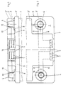
- FIGS. 1 and 2 A first embodiment of a battery is shown in FIGS. 1 and 2.
- the battery has a battery housing 1, on the top 2 of which a cover 3, consisting of a lower cover 3 'and an upper cover 3', is welded on. Both the battery housing 1 and the cover 3 are molded plastic parts. Through the top 2 of the battery housing 1 and in particular through the lower cover 3 ', the two poles 4 of the battery are passed in the form of so-called end poles.
- a plug 6 of an electrical cable connector is fixed in the region of the front upper edge 5 and thus integrated in the cover 3 of the battery housing 1. As can be seen, this plug has 6 electrical contacts 7, nine for each pole 4.
- An electrical connection in the form of a ribbon cable 8 is made between the poles 4 and the contacts 7 of the plug 6.
- the left in the drawing ribbon cable 8 connects the left pole 4 with the nine contacts 7 arranged on the left side of the plug 6, while the right ribbon cable 8 makes the electrical connection on the right side.
- the ribbon cables 8 are laid in a recess 9 in the top 2 of the lower cover 3 '.
- the contacting of the ribbon cable 8 with the poles 4 takes place via arcuate fastening elements 10, which are soldered to the cylindrical peripheral wall of the poles 4.
- the poles 4 have cutouts 11 corresponding to the fastening elements 10.
- the second embodiment of a battery shown in FIGS. 3 and 4 also consists of a battery housing 1 onto which a cover 3 is welded. As can be seen in Fig. 3, the plug 6 between the upper cover 3deck and the lower cover 3 'of the cover 3 is fixed. The connection between the plug 6 and the pole 4 is also made by a ribbon cable 8. This is electrically connected to the pole 4 via a special construction.
- a pole bushing 12 is positively arranged in the lower cover 3 'of the cover 3, a pole bushing 12 is positively arranged. This protrudes over the top of the lower cover 3 '.
- the pole 4 is guided through this pole bushing 12.
- the end of the ribbon cable 8 is provided with a rigid, flat connector 13 made of metal, which has a bore 14. By means of this bore 14, the connector 13 is plugged onto the pole bushing 12. After attaching the connector 13, the pole bushing 12 and the pole 4 are welded together. This is shown in Fig. 3 in the left half of the pole 4 and can be seen. The situation before welding is shown on the right.
- a metal sleeve 15 is on the ribbon cable 8 welded on. This metal sleeve 15 is used to contact a starter cable. The fuse for fixing the starter cable within the metal sleeve 15 is not shown.
- the plug 6 and the metal sleeve 15 are arranged in a common housing 16 and thus form a compact electrical connection to the respective pole 4 of the battery.
- FIGS. 5 to 7 A third embodiment of a battery is shown in FIGS. 5 to 7. This differs from the previous two embodiments in that a metal body 17, for example made of lead, is provided as the electrical connection between the pole 4 and the plug 6 and is embedded in the cover 3 of the battery housing 1.
- the metal body 17 can be molded as a prefabricated part through the cover 3 of the battery housing 1 accordingly.
- the metal sleeve 15 for connecting a starter cable is embedded within the metal body 17.
- the pole 4 of the battery projecting through the metal body 17 is welded to the metal body 17 at the upper end.
- a plug 18 closes the lid 3.
- the fourth embodiment which is shown in FIGS. 8 and 9, differs from the three previous embodiments in the arrangement of the plug 6 in the side wall 19 of the battery housing.
- a receptacle housing 20 is integrally formed on the side wall 19 of the battery housing 1.
- the plug 6 is inserted into this receptacle housing 20 from above, the fixing being carried out by means of a latch 21.
- the electrical connection between the pole 4 and the plug 6 is made by a metal plate 22, for example made of copper, which can be inserted into corresponding slots both in the pole 4 and in the plug 6.
- a contacting device for a starter cable 23 is provided on the other side of the plug 6. This consists of a conical sleeve 24 which is formed in one piece with the pole 4. The starter cable 23 is inserted into this conical sleeve 24 (from the right in the drawing). A screw 25 screwed in from the other side presses the end of the starter cable 23 against the inner wall of the sleeve 24.
- the plug 6 is formed by a separately prefabricated plug component 26 which can be inserted into the cover 3 of the battery housing 1.
- the plug component 26 consists of a plastic molded part 27, which forms the housing for the electrical connections.
- the contacts 7 of the plug 6 and, on the other hand, the elements for establishing the electrical connection to the poles 4 are arranged.
- the latter consist of an electrical contact socket 28, which is provided with contact lamellae 29 around the inner circumference.
- the plastic molded part 27 of the plug component 26 is provided with clamping brackets 30 which, after being inserted into the cover 3, snap into it and thus fix the plug component 26 in the battery housing 1.
- the cover 3 form-fitting pole bushings 12 which protrude above the top of the lower cover 3' and through which the poles 4 are guided.
- the pole bushings 12 are with the Poles 4 welded together to make the electrical connection.
- a solid connecting piece 31 is integrally formed and firmly embedded in the cover 3.
- an electrical contact pin 32 is cast in the connector 31, which protrudes vertically upwards. This contact pin 32 corresponds to the corresponding contact socket 28 in the plug component 26, so that the electrical contact is made after plugging the plug component 26 onto the contact pins 32, this being supported by the contact lamellae 29.
- the plug 6 of the electrical cable connector is firmly integrated within the battery housing 1 or in its cover 3, so that the connector 6 of the electrical cable connector is an integral part of the battery. In this way, a multiple plug connection is realized.
Landscapes
- Chemical & Material Sciences (AREA)
- Chemical Kinetics & Catalysis (AREA)
- Electrochemistry (AREA)
- General Chemical & Material Sciences (AREA)
- Engineering & Computer Science (AREA)
- Manufacturing & Machinery (AREA)
- Connection Of Batteries Or Terminals (AREA)
- Secondary Cells (AREA)
Description
Die Erfindung betrifft eine Batterie, insbesondere Starterbatterie für Kraftfahrzeuge, mit einem Batteriegehäuse, durch das hindurch die Pole der Batterie nach außen hindurchgeführt sind, wobei die Pole jeweils mehrere mit dem Pol elektrisch verbundene elektrische Anschlüsse für ein Anschlußkabel aufweisen.The invention relates to a battery, in particular a starter battery for motor vehicles, with a battery housing through which the poles of the battery are passed to the outside, the poles each having a plurality of electrical connections for the connecting cable that are electrically connected to the pole.
Im heutigen Kraftfahrzeugbau ist man bestrebt, insbesondere den positiven Pol der Starterbatterie mit mehr als einem elektrischen Anschluß zu versehen, um so einen direkten Anschluß diverser elektrischer Geräte zu ermöglichen. In Zukunft ist zu erwarten, daß noch mehr direkte elektrische Anschlüsse bei derartigen Starterbatterien benötigt werden. Darüber hinaus ist bei derartigen Starterbatterien für Kraftfahrzeuge der Zwang zur Automatisierung gefordert, d. h. die Batterie muß robotergerecht ausgebildet sein. Entsprechendes gilt für den negativen Pol (Masserückleitung) der Batterie, wo in Zukunft möglicherweise ebenfalls mehrere Anschlüsse gefordert sind.In today's motor vehicle construction, efforts are made to provide in particular the positive pole of the starter battery with more than one electrical connection, so as to enable a direct connection of various electrical devices. In the future, it is expected that even more direct electrical connections will be required with such starter batteries. In addition, the need for automation is required in such starter batteries for motor vehicles. H. the battery must be robot-compatible. The same applies to the negative pole (ground return line) of the battery, where in the future several connections may also be required.
Eine Batterie der eingangs angegebenen Art ist aus der GB-A-2 038 533 bekannt. Die in dieser Druckschrift offenbarte Batterie weist ein Batteriegehäuse auf, welches oberseitig durch einen Deckel abgeschlossen ist. Durch diesen Deckel sind die Pole der Batterie hindurchgeführt. Oberhalb des Deckels befinden sich Platten, die der Aufnahme von elektrischen Anschlüssen für Anschlußkabel dienen. Diese elektrischen Anschlüsse sind über Drähte mit den Polen verbunden.A battery of the type specified at the outset is known from GB-A-2 038 533. The battery disclosed in this document has a battery housing which is closed at the top by a cover. The poles of the battery are passed through this cover. Above the cover are plates that serve to accommodate electrical connections for connection cables. These electrical connections are connected to the poles by wires.
Die vorbekannte Batterie weist den Nachteil auf, daß sie aufwendig zu fertigen ist. So muß zunächst der den Batterieinnenraum verschließende und die Pole aufweisende Batteriedeckel aufgesetzt werden, um anschließend zuerst die elektrischen Leitungen mit den Polen und den elektrischen Anschlüssen zu verbinden und danach die Platten oberhalb der Platte anzuordnen. Dies ist fertigungstechnisch aufwendig und hat darüber hinaus den Nachteil, daß bei einem Defekt der elektrischen Verdrahtung die gesamte Batterie unbrauchbar ist. Darüber hinaus bestehen bei der vorbekannten Batterie Platzprobleme, da die elektrischen Anschlüsse als mehrere, je einen Kontakt aufweisende Buchsen verteilt auf der Platte angeordnet sind. Als weiterer Nachteil der vorbekannten Batterie ist zu nennen, daß ein vollautomatisiertes Anschließen von Steckern an die Buchsen nicht möglich ist, da die elektrischen Anschlüsse aufweisende Platte bei der Montage der Batterie relativ zu der an der Batterie festgelegten Platte verschiebbar ist. Dadurch ist die Lage der elektrischen Anschlüsse relativ zu der Batterie nicht mit der für ein automatisiertes Einsetzen von Steckern in die Buchsen notwendigen Genauigkeit vorgegeben.The known battery has the disadvantage that it is difficult to manufacture. So first the battery compartment and the poles having battery covers are put on, to then first connect the electrical lines to the poles and the electrical connections and then to arrange the plates above the plate. This is complex in terms of production technology and also has the disadvantage that the entire battery is unusable if the electrical wiring is defective. In addition, there are space problems with the previously known battery, since the electrical connections are arranged on the plate as a plurality of sockets each having a contact. A further disadvantage of the known battery is that a fully automated connection of plugs to the sockets is not possible, since the plate having the electrical connections can be displaced relative to the plate fixed to the battery when the battery is installed. As a result, the position of the electrical connections relative to the battery is not predetermined with the accuracy required for automated insertion of plugs into the sockets.
Davon ausgehend liegt der Erfindung die Aufgabe zugrunde, eine Batterie, insbesondere eine Starterbatterie für Kraftfahrzeuge, mit einem verbesserten elektrischen Anschluß für mehrere Anschlußkabel zu schaffen.Based on this, the object of the invention is to create a battery, in particular a starter battery for motor vehicles, with an improved electrical connection for a plurality of connecting cables.
Als technische Lösung wird mit der Erfindung vorgeschlagen, daß die elektrischen Anschlüsse durch einen, mehrere Kontakte aufweisenden Stecker oder Buchse einer elektrischen Kabelsteckverbindung gebildet sind, wobei der Stecker oder die Buchse dieser elektrischen Kabelsteckverbindung im Batteriegehäuse integriert und fest verbunden ist.As a technical solution , the invention proposes that the electrical connections are formed by a plug or socket of an electrical cable plug connection having a plurality of contacts, the plug or socket of this electrical cable plug connection being integrated and firmly connected in the battery housing.
Auf diese Weise ist ein Mehrfachsteckanschluß einer elektrischen Kabelsteckverbindung geschaffen, welcher eine technisch einfache Möglichkeit darstellt, um mehrere Anschlußkabel mit der Batterie zu kontaktieren. Die Anschlußkabel münden dabei in einer mit dem Stecker bzw. der Buchse der Batterie korrespondierenden, gemeinsamen Buchse bzw. Stecker der elektrischen Kabelsteckverbindung, so daß durch einfaches hineinstecken der Buchse bzw. des Steckers der Anschlußkabel in den Stecker bzw. in die Buchse der Batterie der elektrische Kontakt hergestellt ist. Dadurch werden sämtliche Anschlußkabel gleichzeitig mit der Batterie kontaktiert. Der Stecker oder die Buchse ist dabei ein fester Bestandteil des Batteriegehäuses und kann an beliebiger Stelle in diesem integriert sein. Da der Stecker bzw. die Buchse in dem Batteriegehäuse integriert und mit diesem fest verbunden ist, ist die Lage der Kontakte in Bezug auf die Gehäusegeometrie festgelegt, so daß bei einem vollautomatischen Anschließen der Anschlußkabel die genaue Lage der Steckkontakte exakt durch die Lage der Batterie vorgegeben ist. Ein vollautomatisches Anschließen der Steckkontakte ist somit möglich. Die elektrische Steckverbindung kann zusätzlich oder aber auch anstelle eines der beiden Pole vorgesehen sein.In this way, a multiple connector of an electrical cable connector is created, which is a technically simple way to contact several connection cables with the battery. The connection cables open into a common socket or plug of the electrical cable plug connector corresponding to the plug or socket of the battery, so that the plug or socket of the connection cable into the plug or socket of the battery simply by plugging in the socket or plug electrical contact is established. This means that all connection cables are contacted with the battery at the same time. The plug or socket is an integral part of the battery housing and can be integrated anywhere in this. Since the plug or socket is integrated in the battery housing and is firmly connected to it, the position of the contacts is fixed in relation to the housing geometry, so that the exact position of the plug contacts is predefined exactly by the position of the battery when the connecting cable is connected fully automatically is. A fully automatic connection of the plug contacts is therefore possible. The electrical plug connection can be provided in addition or also instead of one of the two poles.
Vorzugsweise ist der Stecker oder die Buchse der elektrischen Kabelsteckverbindung im Kunststoff des Batteriegehäuses eingebettet, wobei diese Einbettung während des Spritzvorganges des Batteriegehäuses erfolgen kann. Gleichzeitig mit dem Umspritzen des Steckers oder der Buchse kann das Umspritzen der elektrischen Verbindung zu dem Pol erfolgen.The plug or the socket of the electrical cable plug connection is preferably embedded in the plastic of the battery housing, this embedding being able to take place during the injection molding process of the battery housing. Simultaneously with the overmolding of the plug or the socket, the overmolding of the electrical connection to the pole can take place.
Sofern die Batterie ein Batteriegehäuse mit einem Deckel aufweist, kann in einer bevorzugten Weiterbildung der Stecker oder die Buchse der elektrischen Kabelsteckverbindung im Bereich einer der Oberkanten des Batteriegehäuses fest im Deckel integriert sein. Die Steckrichtung der elektrischen Kabelsteckverbindung wird dann vorzugsweise parallel zur Oberseite der Batterie liegen. Die Herstellung einer derartigen Batterie, bei der der Stecker oder die Buchse im Deckel des Batteriegehäuses integriert ist, ist sehr einfach, indem vor dem aufsetzen des Deckels auf das eigentliche Batteriegehäuse dazwischen der Stecker oder die Buchse der elektrischen Kabelsteckverbindung sowie die entsprechende elektrische Verbindung zu dem Pol angeordnet und nach dem Aufsetzen des Deckels dieser mit dem Batteriegehäuse verschweißt wird, so daß der Stecker oder die Buchse fest zwischen dem Deckel und dem Batteriegehäuse festgelegt und in diesem integriert ist. Ist der Deckel ein sogenannter Blockdeckel, bestehend aus Unterdeckel und Oberdeckel, so kann der Stecker oder die Buchse der elektrischen Kabelsteckverbindung zwischen diesen beiden Deckelteilen festgelegt werden.If the battery has a battery housing with a cover, the plug or the socket of the electrical cable connector can be firmly integrated in the cover in the region of one of the upper edges of the battery housing. The direction of insertion of the electrical cable connector will then preferably be parallel to the top of the battery. The production of such a battery, in which the plug or the socket is integrated in the cover of the battery housing, is very simple by placing the plug or the socket of the electrical cable plug connection and the corresponding electrical connection to it before the cover is placed on the actual battery housing Pole arranged and after placing the lid this is welded to the battery housing, so that the plug or socket is fixed between the lid and the battery housing and integrated in this. If the cover is a so-called block cover, consisting of a lower cover and an upper cover, the plug or socket of the electrical cable plug connection can be fixed between these two cover parts.
Alternativ dazu kann der Stecker oder die Buchse der elektrischen Kabelsteckverbindung in einer Seitenwand des Batteriegehäuses fest integriert sein. Dies hat den Vorteil, daß der Deckel der Batterie frei von sämtlichen elektrischen Anschlüssen ist. Allerdings besitzt das Batteriegehäuse etwas größere Abmessungen, wenn der Stecker oder die Buchse auskragend an der Seitenwand des Batteriegehäuses angeordnet ist.Alternatively, the plug or socket of the electrical cable connector can be firmly integrated in a side wall of the battery housing. This has the advantage that the battery cover is free of all electrical connections. However, the battery case has somewhat larger dimensions if the plug or the socket is cantilevered on the side wall of the battery case.
In einer technischen Realisierung dieser Ausführungsform weist die Seitenwand des Batteriegehäuses ein auskragendes, angeformtes Aufnahmegehäuse auf, in das der Stecker oder die Buchse der elektrischen Kabelsteckverbindung einsetzbar und darin festlegbar ist.In a technical implementation of this embodiment, the side wall of the battery housing has a projecting, integrally formed receiving housing, into which the plug or socket of the electrical cable plug connection can be inserted and fixed therein.
Für die beiden Pole der Batterie kann auch ein sogenannter Einheitsanschluß vorgesehen werden, indem in einer Weiterbildung für beide Pole der Batterie ein gemeinsamer Stecker oder eine gemeinsame Buchse der elektrischen Kabelsteckverbindung vorgesehen ist. Dieser Einheitsanschluß ist besonders robotertauglich.A so-called unit connection can also be provided for the two poles of the battery, in that in a further development a common plug or a common socket of the electrical cable plug connection is provided for both poles of the battery. This unit connection is particularly suitable for robots.
In einer ersten Ausführungsform kann die elektrische Verbindung zwischen dem Pol und dem Stecker oder der Buchse der elektrischen Kabelsteckverbindung durch ein Kabel oder ein Flachbandkabel gebildet sein. Dies stellt eine technisch sehr einfache Möglichkeit für die elektrische Zuleitung von dem Pol zu dem entsprechenden Stecker oder der entsprechenden Buchse dar.In a first embodiment, the electrical connection between the pole and the plug or socket of the electrical cable plug connection can be formed by a cable or a ribbon cable. This represents a technically very simple possibility for the electrical supply line from the pole to the corresponding plug or socket.
Dabei kann das dem Pol zugeordnete Ende des Kabels oder des Flachbandkabels mit einem an der zylindrischen Umfangswand des Pols befestigten, korrespondierend bogenförmig ausgebildeten Befestigungselement versehen sein, wobei der Pol eine zu dem Befestigungselement korrespondierende Aussparung zu dessen Aufnahme aufweist. Dabei kann das bogenförmige Befestigungselement beispielsweise am Pol angelötet sein. Auch ist es denkbar, als Befestigungselement eine am Pol aufsteckbare Klammer vorzusehen. Alternativ dazu kann das dem Pol zugeordnete Ende des Kabels oder des Flachbandkabels ein massives Anschlußstück aus Metall aufweisen, das auf den Pol aufgesteckt und mit diesem verschweißt ist. Dabei ist bei dieser alternativen Befestigungsart vorzugsweise zwischen dem Batteriegehäuse und dem Pol eine diese umgebende sowie mit dem Batteriegehäuse formschlüssig verbundene Poldurchführungshülse aus Metall angeordnet, auf die das Anschlußstück aus Metall aufgesteckt ist und wobei der Pol, die Poldurchführungshülse sowie das Anschlußstück miteinander verschweißt sind. Dies stellt eine sehr sichere und dauerhafte Verbindung zwischen dem Stecker oder der Buchse der elektrischen Kabelsteckverbindung und dem Pol dar.In this case, the end of the cable or the ribbon cable assigned to the pole can be designed with a correspondingly arched shape attached to the cylindrical peripheral wall of the pole Fastening element may be provided, the pole having a recess corresponding to the fastening element for receiving it. The arcuate fastener can be soldered to the pole, for example. It is also conceivable to provide a clip that can be attached to the pole as a fastening element. As an alternative to this, the end of the cable or the ribbon cable assigned to the pole can have a solid connecting piece made of metal, which is plugged onto the pole and welded to it. In this alternative type of fastening, a pole bushing sleeve made of metal, which surrounds it and is positively connected to the battery housing, is preferably arranged between the battery housing and the pole, onto which the metal connector is plugged and the pole, the pole bushing sleeve and the connector are welded to one another. This represents a very safe and permanent connection between the plug or socket of the electrical cable connector and the pole.
In einer zweiten Ausführungsform der elektrischen Verbindung zwischen dem Pol und dem Stecker der elektrischen Kabelsteckverbindung wird vorgeschlagen, daß diese durch eine Metallplatte gebildet ist.In a second embodiment of the electrical connection between the pole and the plug of the electrical cable connector, it is proposed that it be formed by a metal plate.
Vorzugsweise ist die elektrische Verbindung zwischen dem Pol und dem Stecker oder der Buchse der elektrischen Kabelsteckverbindung im Kunststoff des Batteriegehäuses eingebettet. Dies hat zum einen den Vorteil, daß die elektrische Verbindung während des Spritzens des Batteriegehäuses von dem Kunststoff umspritzt werden kann. Zum anderen ist die elektrische Verbindung durch die Einbettung im Kunststoff des Batteriegehäuses vor Umwelteinflüssen geschützt.The electrical connection between the pole and the plug or socket of the electrical cable plug connection is preferably embedded in the plastic of the battery housing. On the one hand, this has the advantage that the electrical connection can be encapsulated by the plastic during the injection molding of the battery housing. On the other hand, the electrical connection is protected from environmental influences by being embedded in the plastic of the battery housing.
Alternativ dazu kann die elektrische Verbindung zwischen dem Pol und der Buchse der elektrischen Kabelsteckverbindung vorzugsweise in der Oberseite des Batteriegehäuses eingelegt und dort fixiert sein. Dies gilt insbesondere bei der Verwendung eines Flachbandkabels. In diesem Fall ist die Oberseite des Batteriegehäuses mit einer kanalförmigen Ausnehmung zu versehen, die das Flachbandkabel aufnimmt. Die Fixierung kann mittels einer Klemme erfolgen. Auch die Verlötung ist denkbar.Alternatively, the electrical connection between the pole and the socket of the electrical cable connector can preferably be inserted in the top of the battery housing and fixed there. This is especially true when using a ribbon cable. In this case, the top of the battery housing is to be provided with a channel-shaped recess which receives the ribbon cable. It can be fixed using a clamp. Soldering is also conceivable.
Ausgehend von einer Starterbatterie für Kraftfahrzeuge wird in einer bevorzugten Weiterbildung vorgeschlagen, daß zusätzlich zu dem Stecker oder der Buchse der elektrischen Kabelsteckverbindung eine Metallhülse zum elektrischen Kontaktieren eines Starterkabels für das Kraftfahrzeug vorgesehen ist. Eine derartige Metallhülse bildet eine einfache Steckverbindung für das Starterkabel, so daß ein einfacher robotertauglicher Anschluß möglich ist. Die Metallhülse kann dabei die Ausbildung des Poles in der herkömmlichen Weise entbehrlich machen, so daß lediglich eine elektrisch leitenden Durchführung durch das Batteriegehäuse erforderlich ist.Starting from a starter battery for motor vehicles, it is proposed in a preferred development that, in addition to the plug or socket of the electrical cable connector, a metal sleeve is provided for electrically contacting a starter cable for the motor vehicle. Such a metal sleeve forms a simple plug connection for the starter cable, so that a simple robot-compatible connection is possible. The metal sleeve can make the formation of the pole in the conventional manner unnecessary, so that only an electrically conductive passage through the battery housing is required.
In einer bevorzugten Weiterbildung dieser Starterbatterie kann der Stecker oder die Buchse der elektrischen Kabelsteckverbindung sowie der Metallhülse für das Starterkabel in einem gemeinsamen Gehäuse angeordnet sein. Dies stellt einen sehr kompakten elektrischen Anschluß an die Starterbatterie dar.In a preferred development of this starter battery, the plug or socket of the electrical cable plug connection and the metal sleeve for the starter cable can be arranged in a common housing. This represents a very compact electrical connection to the starter battery.
Als dritte Ausführungsform der elektrischen Verbindung zwischen dem Pol und dem Stecker oder der Buchse der elektrischen Kabelsteckverbindung sowie gegebenenfalls der Metallhülse kann ein im Batteriegehäuse eingebetteter Metallkörper vorgesehen sein, in dem die Metallhülse gegebenenfalls eingebettet ist. Ein derartiger Metallkörper hat den Vorteil, daß er auf technisch sehr einfache Weise innerhalb der Batteriegehäuses eingebettet werden kann, indem er als vorgefertigtes Teil während des Spritzvorganges des Batteriegehäuses vom Kunststoff umspritzt wird. Insbesondere kann der Metallkörper, der beispielsweise aus Blei bestehen kann, im Deckel des Batteriegehäuses angeordnet sein. Durch das Einbetten der Metallhülse für das Starterkabel wird insbesondere ein einstückiges Teil geschaffen, das sehr leicht handhabbar ist. Der Metallkörper ist dabei vorzugsweise mit dem Pol der Batterie verschweißt, so daß ein einwandfrier elektrischer Kontakt gewährleistet ist.As a third embodiment of the electrical connection between the pole and the plug or socket of the electrical cable plug connection and optionally the metal sleeve, a metal body embedded in the battery housing can be provided, in which the metal sleeve is optionally embedded. Such a metal body has the advantage that it is technically can be embedded in a very simple manner within the battery housing, in that it is encapsulated by the plastic as a prefabricated part during the injection molding process of the battery housing. In particular, the metal body, which can be made of lead, for example, can be arranged in the cover of the battery housing. Embedding the metal sleeve for the starter cable creates a one-piece part that is very easy to handle. The metal body is preferably welded to the pole of the battery, so that a perfect electrical contact is guaranteed.
Weiterhin wird eine Ausführungsform einer Batterie vorgeschlagen, bei der der Stecker oder die Buchse der elektrischen Kabelsteckverbindung ein vorgefertigtes Stecker- oder Buchsenbauteil ist, das in das Batteriegehäuse unter Herstellung der elektrischen Verbindung zum Pol einsetzbar ist. Ein derartiges vorgefertigtes Stecker- oder Buchsenbauteil hat den Vorteil, daß es als separates Bauteil hergestellt werden kann, das je nach Bedarf in das Batteriegehäuse eingesetzt wird und so der Stecker oder die Buchse der elektrischen Kabelsteckverbindung im Batteriegehäuse integriert ist. Die Möglichkeit der nachträglichen Montage des Steckers oder der Buchse der elektrischen Kabelsteckverbindung ist dabei außerordentlich gut für eine Robotermontage geeignet. Darüber hinaus hat diese Ausführungsform den Vorteil, daß je nach Bedarf unterschiedliche Stecker- oder Buchsenbauteile im Batteriegehäuse eingesetzt werden können.Furthermore, an embodiment of a battery is proposed in which the plug or the socket of the electrical cable plug connection is a prefabricated plug or socket component which can be inserted into the battery housing while establishing the electrical connection to the pole. Such a prefabricated plug or socket component has the advantage that it can be manufactured as a separate component which is inserted into the battery housing as required and so the plug or socket of the electrical cable connector is integrated in the battery housing. The possibility of retrofitting the plug or the socket of the electrical cable connector is extremely well suited for robot assembly. In addition, this embodiment has the advantage that different plug or socket components can be used in the battery housing as required.
In einer Weiterbildung dieser Ausführungsform wird vorgeschlagen, daß für die Herstellung der elektrischen Verbindung im Batteriegehäuse ein mit dem jeweiligen Pol elektrisch verbundener elektrischer Kontaktstift fest angeordnet ist und das vorgefertigte Stecker- oder Buchsenbauteil eine dazu korrespondierende elektrische Kontaktbuchse aufweist. Dies stellt eine technisch sehr einfache und vor allem roboterfreundliche Möglichkeit zur Herstellung der elektrischen Verbindung zwischen den Polen und dem Stecker- oder Buchsenbauteil dar.In a further development of this embodiment, it is proposed that for the establishment of the electrical connection in the battery housing, an electrically connected to the respective pole electrical contact pin is fixed and the prefabricated plug or socket component has a corresponding electrical contact socket. This represents a technically very simple and, above all, robot-friendly option for establishing the electrical connection between the poles and the plug or socket component.
Zur Sicherung des Stecker- oder Buchsenbauteils im Batteriegehäuse wird in einer Weiterbildung eine zwischen dem Batteriegehäuse und dem vorgefertigten Stecker- oder Buchsenbauteil angeordnete Rasteinrichtung vorgeschlagen, die beispielsweise ein Klemmbügel sein kann.In order to secure the plug or socket component in the battery housing, a latching device arranged between the battery housing and the prefabricated plug or socket component is proposed in a further development, which can be, for example, a clamping bracket.
Schließlich wird eine Ausführungsform einer Batterie vorgeschlagen, bei der der elektrische Anschluß durch einen mit dem Pol elektrisch verbundenen Draht gebildet ist, auf dem einzelne mit ihm elektrisch verbundene Stecker oder Buchsen des elektrischen Anschlusses für die Kontaktierung jeweils eines Anschlußkabels angeordnet sind. Auf diese Weise wird ein technisch überaus einfacher sowie im Batteriegehäuse der Batterie integrierter elektrischer Mehrfachanschluß geschaffen, der lediglich aus einem mit dem Pol der Batterie zu verbindenden Draht und den Anschlußbolzen für die Stecker oder Buchsen für die elektrische Kontaktierung jeweils eines Anschlußkabels besteht. Durch ein einfaches Biegen des Drahtes ist auf technisch einfache Weise eine Anordnung der Stecker oder Buchsen entsprechend den Erfordernissen möglich. Durch lediglich zwei unterschiedliche Bauteile, nämlich einem Draht und bolzenähnlichen Steckern oder Buchsen, lassen sich auf überaus variable Weise die unterschiedlichsten Zusatzanschlüsse der Batterie schaffen, die darüber hinaus sicher und einfach am Batteriepol angeschlossen sind.Finally, an embodiment of a battery is proposed in which the electrical connection is formed by a wire electrically connected to the pole, on which individual plugs or sockets of the electrical connection electrically connected to it are arranged for contacting one connection cable each. In this way, a technically extremely simple and integrated in the battery housing of the battery electrical multiple connection is created, which consists only of a wire to be connected to the pole of the battery and the connecting bolts for the plugs or sockets for the electrical contacting of a connecting cable. By simply bending the wire, an arrangement of the plugs or sockets according to the requirements is possible in a technically simple manner. With just two different components, namely a wire and bolt-like plugs or sockets, the most varied of additional battery connections can be created in an extremely variable manner, which are also connected securely and easily to the battery pole.
Die Stecker oder Buchsen sind als Einzelstecker oder Einzelbuchsen auszubilden, an denen jeweils ein Anschlußkabel angeschlossen wird, doch können in einer Weiterbildung mehrere der Einzelstecker oder Einzelbuchsen zu einer Baugruppe zusammengefaßt sein. Beispielsweise können die Stecker oder Buchsen durch einen gemeinsamen Block zusammengefaßt sein, der am Draht befestigt ist.The plugs or sockets are to be designed as individual plugs or individual sockets, to each of which a connecting cable is connected, but in a further development several of the individual plugs or individual sockets can be combined to form a module. For example, the plugs or sockets can be combined by a common block that is attached to the wire.
Vorzugsweise ist der Draht ein Runddraht insbesondere aus Messing.The wire is preferably a round wire, in particular made of brass.
In einer bevorzugten Weiterbildung weist der Draht eine Bohrung auf, in die der Draht für die elektrische Verbindung hineingesteckt ist. Die Aufnahme des Drahtes in einer derartigen in Pol ausgebildeten Bohrung stellt eine technisch einfache und zuverlässige Maßnahme dar, um den Draht sowohl mechanisch als auch elektrisch mit dem Batteriepol zu verbinden. Die endgültige Verbindung des Drahtes mit dem Pol kann dabei beispielsweise durch Vergießen mit Zinn erfolgen.In a preferred development, the wire has a bore into which the wire for the electrical connection is inserted. The inclusion of the wire in such a hole formed in a pole represents a technically simple and reliable measure to connect the wire to the battery pole both mechanically and electrically. The final connection of the wire to the pole can be done, for example, by casting with tin.
Eine weitere bevorzugte Weiterbildung schlägt vor, daß die einzelnen Stecker oder Buchsen jeweils eine Bohrung aufweisen, mittels denen sie auf den Draht hintereinander aufgesteckt sind. Diese Anordnung der Stecker oder Buchsen, indem diese gewissermaßen wie die Perlen auf einer Schnur auf dem Draht aufgereiht sind, stellt eine technisch einfache Möglichkeit zur Befestigung der bolzenartigen Stecker oder Buchsen am Draht dar, wobei nach dem Auffädeln die Stecker oder Buchsen vorzugsweise mit dem Draht weicht verlötet werden, um so eine einwandfreie elektrische Kontaktierung herzustellen.A further preferred development proposes that the individual plugs or sockets each have a bore by means of which they are plugged onto the wire one behind the other. This arrangement of the plugs or sockets, in that they are lined up on a wire on the wire to a certain extent like the pearls, represents a technically simple possibility for fastening the bolt-like plugs or sockets to the wire, the plugs or sockets preferably being attached to the wire after threading soft soldered to make a perfect electrical contact.
Um die Stecker oder Buchsen in der richtigen Lage auf dem Draht positionieren zu können, wird in einer Weiterbildung eine Zentrierplatte vorgeschlagen, mittels der die Stecker oder Buchsen in ihrer vorgegebenen Position gehalten werden, um sie anschließend mit dem Draht zu verlöten.In order to be able to position the plugs or sockets in the correct position on the wire, a further training is used Centering plate proposed by means of which the plugs or sockets are held in their predetermined position in order to then solder them to the wire.
In einer Weiterbildung ist der Draht mit seinen Steckern oder Buchsen im Kunststoff des Batteriegehäuses, insbesondere in dessen Deckel eingebettet. Dies stellt eine einfache Möglichkeit zum Integrieren des elektrischen Anschlusses im Batteriegehäuse und insbesondere in dessen Deckel dar, indem der elektrische Anschluß mit seinem Draht und mit seinen Steckern oder Buchsen entsprechend mit Kunststoff umspritzt wird. Sofern Stecker vorgesehen sind, ragen diese dann über die Oberseite des Batteriegehäuses bzw. über die Oberseite des Batteriedeckels. Sofern es sich bei den elektrischen Anschlüssen um Buchsen handelt, können diese mehr oder weniger versenkt im Batteriegehäuse eingebettet sein, so daß durch Einführen eines entsprechenden Steckers des Anschlußkabels dieses mit der Buchse kontaktiert werden kann.In one development, the wire with its plugs or sockets is embedded in the plastic of the battery housing, in particular in its cover. This represents a simple possibility for integrating the electrical connection in the battery housing and in particular in its cover, in that the electrical connection with its wire and with its plugs or sockets is extrusion-coated accordingly with plastic. If plugs are provided, they then protrude over the top of the battery housing or over the top of the battery cover. If the electrical connections are sockets, they can be embedded in the battery housing to a greater or lesser extent so that they can be contacted with the socket by inserting a corresponding plug of the connecting cable.
Um eine optimale Verankerung des bolzenartigen Steckers oder der bolzenartigen Buchse im Kunststoffmaterial zu gewährleisten, weisen die Stecker oder Buchsen im im Kunststoff eingebetteten Bereich vorzugsweise eine unrunde Außenkontur auf, die beispielsweise eine Rändelung sein kann. Dies erweist sich insbesondere dann von Vorteil, wenn der Stecker ein Schraubgewinde zum Aufschrauben des Anschlußkabels aufweist, so daß die Anschraubmomente von der Kunststoffumspritzung aufgefangen werden.In order to ensure optimal anchoring of the pin-like plug or the pin-like socket in the plastic material, the plugs or sockets in the area embedded in the plastic preferably have a non-circular outer contour, which can be knurled, for example. This proves to be particularly advantageous if the plug has a screw thread for screwing on the connecting cable, so that the screwing moments are absorbed by the plastic encapsulation.
In einer bevorzugten Weiterentwicklung der Stecker oder Buchsen sind diese vorzugsweise Drehteile insbesondere aus Rundmessing, so daß die bereits erwähnten elektrischen Anschlußbolzen auf technisch einfache Weise geschaffen sind.In a preferred further development of the plugs or sockets, these are preferably turned parts, in particular made of round brass, so that the electrical connection bolts already mentioned are created in a technically simple manner.
Um eine einfache Kontaktierung des jeweiligen Anschlußkabels am Stecker zu gewährleisten, weist dieses vorzugsweise ein Schraubgewinde auf.In order to ensure simple contacting of the respective connection cable on the plug, this preferably has a screw thread.
Weitere Einzelheiten, Merkmale und Vorteile ergeben sich aus der nachfolgenden Beschreibung der zugehörigen Zeichnungen, in denen verschiedene Ausführungsformen einer erfindungsgemäßen Batterie schematisch dargestellt sind. In den Zeichnungen zeigt:
- Fig. 1
- eine Vorderansicht einer ersten Ausführungsform einer Batterie im Bereich des Deckels;
- Fig. 2
- eine Draufsicht auf die Batterie in Fig. 1;
- Fig. 3
- eine teilweise entlang der Linie III-III in Fig. 4 geschnittene Vorderansicht einer zweiten Ausführungsform einer Batterie;
- Fig. 4
- eine Draufsicht auf die Batterie in Fig. 3;
- Fig. 5
- eine teilweise Vorderansicht einer dritten Ausführungsform einer Batterie;
- Fig. 6
- eine Draufsicht auf die Batterie in Fig. 5, wobei im Bereich des Poles der Deckel weggebrochen ist;
- Fig. 7
- einen Schnitt entlang der Linie VII-VII in Fig. 6;
- Fig. 8
- eine teilweise Seitenansicht einer vierten Ausführungsform einer Batterie;
- Fig. 9
- einen Schnitt entlang der Linie IX-IX in Fig. 8;
- Fig. 10
- eine teilweise Vorderansicht einer fünften Ausführungsform einer Batterie, wobei die linke Hälfte entlang der Linie X - X in Fig. 11 geschnitten ist;
- Fig. 11
- eine Draufsicht auf die Batterie in Fig. 10.
- Fig. 1
- a front view of a first embodiment of a battery in the region of the lid;
- Fig. 2
- a plan view of the battery in Fig. 1;
- Fig. 3
- a front view partly in section along the line III-III in Fig. 4 of a second embodiment of a battery;
- Fig. 4
- a plan view of the battery in Fig. 3;
- Fig. 5
- a partial front view of a third embodiment of a battery;
- Fig. 6
- a plan view of the battery in Figure 5, with the cover broken away in the region of the pole;
- Fig. 7
- a section along the line VII-VII in Fig. 6;
- Fig. 8
- a partial side view of a fourth embodiment of a battery;
- Fig. 9
- a section along the line IX-IX in Fig. 8;
- Fig. 10
- a partial front view of a fifth embodiment of a battery, the left half being cut along the line X - X in Fig. 11;
- Fig. 11
- 10 shows a plan view of the battery in FIG. 10.
Eine erste Ausführungsform einer Batterie ist in den Fig. 1 und 2 dargestellt. Die Batterie weist ein Batteriegehäuse 1 auf, auf dessen Oberseite 2 ein Deckel 3, bestehend aus einem Unterdeckel 3′ sowie aus einem Oberdeckel 3˝, aufgeschweißt ist. Sowohl beim Batteriegehäuse 1 als auch beim Deckel 3 handelt es sich um Kunststofformteile. Durch die Oberseite 2 des Batteriegehäuses 1 und dabei insbesondere durch den Unterdeckel 3′ sind die beiden Pole 4 der Batterie in Form von sogenannten Endpolen hindurchgeführt.A first embodiment of a battery is shown in FIGS. 1 and 2. The battery has a
Zwischen dem Unterdeckel 3′ und dem Oberdeckel 3˝ des Deckels 3 ist im Bereich der vorderen Oberkante 5 ein Stecker 6 einer elektrischen Kabelsteckverbindung festgelegt und somit im Deckel 3 des Batteriegehäuses 1 integriert. Wie zu erkennen ist, besitzt dieser Stecker 6 elektrische Kontakte 7, und zwar jeweils neun für jeden Pol 4.Between the lower cover 3 'and the
Zwischen den Polen 4 und den Kontakten 7 des Steckers 6 ist jeweils eine elektrische Verbindung in Form eines Flachbandkabels 8 hergestellt. Das in der Zeichnung linke Flachbandkabel 8 verbindet dabei den linken Pol 4 mit den neun auf der linken Seite des Steckers 6 angeordneten Kontakten 7, während das rechte Flachbandkabel 8 die elektrische Verbindung auf der rechten Seite herstellt. Die Flachbandkabel 8 sind dabei in einer Ausnehmung 9 in der Oberseite 2 des Unterdeckels 3′ verlegt. Die Kontaktierung der Flachbandkabel 8 mit den Polen 4 erfolgt über bogenförmige Befestigungselemente 10, die an der zylindrischen Umfangswand der Pole 4 angelötet sind. Zur besseren Fixierung weisen die Pole 4 zu den Befestigungselementen 10 korrespondierende Aussparungen 11 auf.An electrical connection in the form of a
Die in den Fig. 3 und 4 dargestellte zweite Ausführungsform einer Batterie besteht ebenfalls aus einem Batteriegehäuse 1, auf das ein Deckel 3 aufgeschweißt ist. Wie in Fig. 3 zu erkennen ist, ist der Stecker 6 zwischen dem Oberdeckel 3˝ und dem Unterdeckel 3′ des Deckels 3 festgelegt. Die Verbindung zwischen dem Stecker 6 und dem Pol 4 wird ebenfalls durch ein Flachbandkabel 8 hergestellt. Dieses ist über eine besondere Konstruktion elektrisch mit dem Pol 4 verbunden.The second embodiment of a battery shown in FIGS. 3 and 4 also consists of a
Im Unterdeckel 3′ des Deckels 3 ist formschlüssig eine Poldurchführungshülse 12 angeordnet. Diese ragt über die Oberseite des Unterdeckels 3′. Durch diese Poldurchführungshülse 12 hindurch ist der Pol 4 geführt. Das Ende des Flachbandkabels 8 ist mit einem starren, flachen Anschlußstück 13 aus Metall versehen, das eine Bohrung 14 aufweist. Mittels dieser Bohrung 14 ist das Anschlußstück 13 auf die Poldurchführungshülse 12 aufgesteckt. Nach dem Aufstecken werden das Anschlußstück 13, die Poldurchführungshülse 12 sowie der Pol 4 miteinander verschweißt. Dies ist in Fig. 3 in der linken Hälfte des Poles 4 dargestellt und zu erkennen. Auf der rechten Seite ist die Situation vor dem Verschweißen dargestellt.In the lower cover 3 'of the
Zusätzlich ist auf das Flachbandkabel 8 eine Metallhülse 15 aufgeschweißt. Diese Metallhülse 15 dient zum Kontaktieren eines Starterkabels. Die Sicherung zum Fixieren des Starterkabels innerhalb der Metallhülse 15 ist nicht dargestellt. Der Stecker 6 sowie die Metallhülse 15 sind in einem gemeinsamen Gehäuse 16 angeordnet und bilden somit einen kompakten elektrischen Anschluß an den jeweiligen Pol 4 der Batterie.In addition, a
Eine dritte Ausführungsform einer Batterie ist in den Fig. 5 bis 7 dargestellt. Diese unterscheidet sich von den vorhergehenden beiden Ausführungsformen dadurch, daß als elektrische Verbindung zwischen dem Pol 4 und dem Stecker 6 ein Metallkörper 17 beispielsweise aus Blei vorgesehen ist, der in dem Deckel 3 des Batteriegehäuses 1 eingebettet ist. Der Metallkörper 17 kann dabei als vorgefertigtes Teil durch den Deckel 3 des Batteriegehäuses 1 entsprechend umspritzt werden. Zusätzlich ist innerhalb des Metallkörpers 17 die Metallhülse 15 für den Anschluß eines Starterkabels eingebettet. Der den Metallkörper 17 durchragende Pol 4 der Batterie ist am oberen Ende mit dem Metallkörper 17 verschweißt. Ein Stopfen 18 verschließt den Deckel 3.A third embodiment of a battery is shown in FIGS. 5 to 7. This differs from the previous two embodiments in that a
Die vierte Ausführungsform, die in den Fig. 8 und 9 dargestellt ist, unterscheidet sich von den drei vorhergehenden Ausführungsformen in der Anordnung des Steckers 6 in der Seitenwand 19 des Batteriegehäuses. Zur Fixierung des Steckers 6 ist dabei ein Aufnahmegehäuse 20 an der Seitenwand 19 des Batteriegehäuses 1 angeformt. In dieses Aufnahmegehäuse 20 wird von oben der Stecker 6 eingesetzt, wobei die Fixierung mittels einer Rastnase 21 erfolgt. Die elektrische Verbindung zwischen dem Pol 4 und dem Stecker 6 wird durch eine Metallplatte 22 beispielsweise aus Kupfer hergestellt, die in entsprechende Schlitze sowohl im Pol 4 als auch im Stecker 6 einschiebbar ist.The fourth embodiment, which is shown in FIGS. 8 and 9, differs from the three previous embodiments in the arrangement of the
Auf der anderen Seite des Steckers 6 ist eine Kontaktiereinrichtung für ein Starterkabel 23 vorgesehen. Diese besteht aus einer konusförmigen Hülse 24, die einstückig mit dem Pol 4 ausgebildet ist. In diese konusförmige Hülse 24 ist (in der Zeichnung von rechts) das Starterkabel 23 eingeschoben. Eine von der anderen Seite her eingeschraubte Schraube 25 drückt das Ende des Starterkabels 23 gegen die Innenwandung der Hülse 24.A contacting device for a
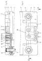
In den Fig. 10 und 11 ist schließlich die fünfte Ausführungsform einer Batterie dargestellt. Bei dieser Ausführungsform ist der Stecker 6 durch ein separat vorgefertigtes Steckerbauteil 26 gebildet, das in den Deckel 3 des Batteriegehäuses 1 einsetzbar ist. Das Steckerbauteil 26 besteht dabei aus einem Kunststofformteil 27, das das Gehäuse für die elektrischen Anschlüsse bildet. In diesem Kunststofformteil 27 sind einerseits die Kontakte 7 des Steckers 6 sowie andererseits die Elemente zur Herstellung der elektrischen Verbindung zu den Polen 4 angeordnet. Letztere bestehen aus einer elektrischen Kontaktbuchse 28, die um den Innenumfang herum mit Kontaktlamellen 29 versehen ist. An der Außenseite ist das Kunststofformteil 27 des Steckerbauteils 26 mit Klemmbügeln 30 versehen, die nach Einsetzen in den Deckel 3 in diesem einrasten und somit das Steckerbauteil 26 im Batteriegehäuse 1 fixieren.Finally, the fifth embodiment of a battery is shown in FIGS. 10 and 11. In this embodiment, the
Ebenso wie bei der in Fig.3 und 4 dargestellten Ausführungsform sind bei dieser fünften Ausführungsform im Unterdeckel 3′ des Deckels 3 formschlüssig Poldurchführungshülsen 12 angeordnet, die über die Oberseite des Unterdeckels 3′ ragen und durch die hindurch die Pole 4 geführt sind. Wie in Fig.10 zu erkennen ist, sind die Poldurchführungshülsen 12 mit den Polen 4 zur Herstellung der elektrischen Verbindung miteinander verschweißt. Im unteren Bereich der Poldurchführungshülsen 12 ist jeweils ein massives Verbindungsstück 31 einstückig angeformt und fest im Deckel 3 eingebettet. Am dem Steckerbauteil 26 zugeordneten Ende ist in dem Verbindungsstück 31 jeweils ein elektrischer Kontaktstift 32 eingegossen, der senkrecht nach oben ragt. Dieser Kontaktstift 32 korrespondiert mit der entsprechenden Kontaktbuchse 28 im Steckerbauteil 26, so daß nach Aufstecken des Steckerbauteils 26 auf die Kontaktstifte 32 der elektrische Kontakt hergestellt ist, wobei dies durch die Kontaktlamellen 29 unterstützt wird.Just as in the embodiment shown in Fig.3 and 4 are in this fifth embodiment in the lower cover 3 'of the
Bei sämtlichen Auführungsformen der Batterie ist der Stecker 6 der elektrischen Kabelsteckverbindung innerhalb des Batteriegehäuses 1 bzw. in dessen Deckel 3 fest integriert, so daß der Stecker 6 der elektrischen Kabelsteckverbindung ein fester Bestandteil der Batterie ist. Auf diese Weise ist ein Mehrfachsteckanschluß realisiert.In all embodiments of the battery, the
- 11
- BatteriegehäuseBattery case
- 22nd
- OberseiteTop
- 33rd
- Deckelcover
- 3′3 ′
- UnterdeckelLower cover
- 3˝3˝
- OberdeckelTop cover
- 44th
- Polpole
- 55
- OberkanteTop edge
- 66
- Steckerplug
- 77
- KontaktContact
- 88th
- FlachbandkabelRibbon cable
- 99
- AusnehmungRecess
- 1010th
- BefestigungselementFastener
- 1111
- AussparungRecess
- 1212th
- PoldurchführungshülsePole grommet
- 1313
- AnschlußstückConnector
- 1414
- Bohrungdrilling
- 1515
- MetallhülseMetal sleeve
- 1616
- Gehäusecasing
- 1717th
- MetallkörperMetal body
- 1818th
- StopfenPlug
- 1919th
- SeitenwandSide wall
- 2020th
- AufnahmegehäuseReceptacle
- 2121
- RastnaseLatch
- 2222
- MetallplatteMetal plate
- 2323
- StarterkabelStarter cable
- 2424th
- HülseSleeve
- 2525th
- Schraubescrew
- 2626
- SteckerbauteilConnector component
- 2727
- KunststofformteilPlastic molding
- 2828
- KontaktbuchseContact socket
- 2929
- KontaktlamelleContact lamella
- 3030th
- KlemmbügelClamp
- 3131
- VerbindungsstückConnector
- 3232
- KontaktstiftContact pin
Claims (30)
- Battery, in particular starter battery for motor vehicles, with a battery housing (1) through which the terminals (4) of the battery extend to the outside, wherein the terminals (4) in each case comprise several electrical connections for a connecting cable, which are electrically connected to the terminal (4), characterised in that the electrical connections are formed by a plug (6) or socket of an electrical plug-in cable connection, comprising several contacts (7), wherein the plug (6) or the socket of this electrical plug-in cable connection is integrated in the battery housing (1) and rigidly connected.
- Battery according to claim 1, characterised in that the plug (6) or socket of the electrical plug-in cable connection is embedded in the plastic of the battery housing (1).
- Battery according to either of claims 1 to 2, wherein the battery housing (1) comprises a cover (3), characterised in that the plug (6) or socket of the electrical plug-in cable connection, in the region of one of the upper edges (5) of the battery housing (1), is rigidly integrated in the cover (3).
- Battery according to either of claims 1 to 2, characterised in that the plug (6) or socket of the electrical plug-in cable connection is rigidly integrated in a side wall (19) of the battery housing (1).
- Battery according to claim 4, characterised in that the side wall (19) of the battery housing (1) comprises a projecting, integrally formed receiving housing (20) in which the plug (6) or socket of the electrical plug-in cable connection can be inserted and fixed therein.
- Battery according to any of claims 1 to 5, characterised in that a common plug (6) or a common socket of the electrical plug-in cable connection is provided for both terminals of the battery.
- Battery according to any of claims 1 to 6, characterised in that the electrical connection between the terminal (4) and the plug (6) or socket of the electrical plug-in cable connection is formed by a cable or a ribbon cable (8).
- Battery according to claim 7, characterised in that the end of the cable or ribbon cable (8) associated with the terminal (4) is provided with a fastening element (10) which is fastened to the cylindrical peripheral wall of the terminal (4) and of matching arcuate shape, wherein the terminal (4) comprises a recess (11) matching the fastening element (10) for receipt thereof.
- Battery according to claim 7, characterised in that the end of the cable or ribbon cable (8) associated with the terminal (4) comprises a solid metal connecting piece (13) which is fitted on the terminal (4) and welded thereto.
- Battery according to claim 9, characterised in that between the battery housing (1) and the terminal (4) is arranged a metal terminal bushing (12) which surrounds the latter and is also connected in form-locking relationship to the battery housing (1) and on which the metal connecting piece (13) is fitted, and wherein the terminal (4), the terminal bushing (12) and also the connecting piece (13) are welded together.
- Battery according to any of claims 1 to 6, characterised in that the electrical connection between the terminal (4) and the plug (6) or socket of the electrical plug-in cable connection is formed by a metal plate (22).
- Battery according to any of claims 1 to 11, characterised in that the electrical connection between the terminal (4) and the plug (6) or socket of the electrical plug-in cable connection is embedded in the plastic of the battery housing (1).
- Battery according to any of claims 1 to 11, characterised in that the electrical connection between the terminal (4) and the plug (6) or socket of the electrical plug-in cable connection is laid in the battery housing (1) and fixed there.
- Starter battery for motor vehicles according to any of claims 1 to 13, characterised in that, in addition to the plug (6) or socket of the electrical plug-in cable connection, a metal bushing (15) is provided for electrical contacting of a starter cable for the motor vehicle.
- Starter battery according to claim 14, characterised in that the plug (6) or socket of the electrical plug-in cable connection as well as the metal bushing (15) for the starter cable are arranged in a common housing (16).
- Battery according to any of claims 1 to 15, characterised in that as the electrical connection between the terminal (4) and the plug (6) or socket of the electrical plug-in cable connection as well as, if occasion arises, the metal bushing (15), a metal body (17) is provided which is embedded in the battery housing (1) and in which the metal bushing (15) is embedded if occasion arises.
- Battery according to claim 16, characterised in that the metal body (17) is welded to the terminal (4).
- Battery according to any of claims 1 to 17, characterised in that the plug (6) or socket of the electrical plug-in cable connection is a prefabricated plug or socket component (26) which can be inserted in the battery housing (1), making the electrical connection to the terminal (4).
- Battery according to claim 18, characterised in that, for making the electrical connection, in the battery housing (1) is rigidly arranged an electrical contact pin (32) electrically connected to the respective terminal (4), and the prefabricated plug or socket component (26) comprises an electrical contact socket (28) matching it.
- Battery according to claim 18 or 20, characterised in that between the battery housing (1) and the prefabricated plug or socket component (26) is arranged a latching device (clamping strap 30).
- Battery according to claim 1, characterised in that the electrical connection is formed by a wire which is electrically connected to the terminal and on which are arranged individual plugs (6) or sockets of the electrical connection electrically connected thereto for contacting a connecting cable each.
- Battery according to claim 21, characterised in that several of the individual plugs or individual sockets are combined into a subassembly.
- Battery according to claim 21 or 22, characterised in that the wire is a round wire particularly made of brass.
- Battery according to any of claims 21 to 23, characterised in that the terminal (4) comprises a bore in which the wire for the electrical connection is inserted.
- Battery according to any of claims 21 to 24, characterised in that the individual plugs (6) or sockets each comprise a bore by means of which they are fitted on the wire-one behind the other.
- Battery according to claim 25, characterised in that a centring plate is provided for positioning the individual plugs (6) or sockets on the wire.
- Battery according to any of claims 21 or 26, characterised in that the wire with its plugs (6) or sockets is embedded in the plastic of the battery housing (1), particularly in the cover (3) thereof.
- Battery according to claim 27, characterised in that the plugs (6) or sockets in the region embedded in the plastic have a non-round outer contour.
- Battery according to any of claims 21 to 28, characterised in that the plugs (6) or sockets are turned parts particularly of round brass.
- Battery according to any of claims 21 to 29, characterised in that the plugs (6) comprise a screw thread for contacting of the connecting cable.
Applications Claiming Priority (3)
| Application Number | Priority Date | Filing Date | Title |
|---|---|---|---|
| DE3821861A DE3821861C1 (en) | 1988-06-29 | 1988-06-29 | |
| DE8808322U DE8808322U1 (en) | 1988-06-29 | 1988-06-29 | |
| DE3821861 | 1988-06-29 |
Publications (3)
| Publication Number | Publication Date |
|---|---|
| EP0349473A2 EP0349473A2 (en) | 1990-01-03 |
| EP0349473A3 EP0349473A3 (en) | 1990-09-05 |
| EP0349473B1 true EP0349473B1 (en) | 1995-06-14 |
Family
ID=25869535
Family Applications (1)
| Application Number | Title | Priority Date | Filing Date |
|---|---|---|---|
| EP89710046A Expired - Lifetime EP0349473B1 (en) | 1988-06-29 | 1989-05-20 | Battery, particularly a car battery |
Country Status (3)
| Country | Link |
|---|---|
| EP (1) | EP0349473B1 (en) |
| DE (3) | DE8808322U1 (en) |
| ES (1) | ES2074477T3 (en) |
Cited By (1)
| Publication number | Priority date | Publication date | Assignee | Title |
|---|---|---|---|---|
| WO2024033334A1 (en) * | 2022-08-12 | 2024-02-15 | Mercedes-Benz Group AG | Battery housing for at least two battery modules |
Families Citing this family (8)
| Publication number | Priority date | Publication date | Assignee | Title |
|---|---|---|---|---|
| DE8808322U1 (en) * | 1988-06-29 | 1988-08-18 | Accumulatorenwerke Hoppecke Carl Zoellner & Sohn Gmbh & Co Kg, 5790 Brilon, De | |
| DE4018856A1 (en) * | 1990-06-13 | 1991-12-19 | Felchner Kg Dr Ing | Battery terminal and switching device for mine locomotive - has counter-contacts of multipole battery plug connector in protective coupling casing |
| DE9419278U1 (en) * | 1994-12-02 | 1995-01-26 | Vb Autobatterie Gmbh | Accumulator battery |
| EP1526610B1 (en) * | 2000-03-07 | 2006-12-20 | Sumitomo Wiring Systems, Ltd. | A construction for preventing erroneous assembling of battery terminals, a battery and a set of terminals |
| DE10012387C2 (en) | 2000-03-14 | 2002-10-02 | Itt Mfg Enterprises Inc | Arrangement for connecting a cable to a motor vehicle battery pole |
| DE102005001669B4 (en) * | 2005-01-13 | 2011-03-24 | Tyco Electronics Amp Gmbh | Connection unit for connecting several consumers to a battery |
| EP3293831B1 (en) * | 2016-09-09 | 2021-07-21 | Siemens Energy Global GmbH & Co. KG | Electrical assembly and adapter element for an electrical apparatus |
| DE102017223225A1 (en) | 2017-12-19 | 2019-06-19 | Volkswagen Aktiengesellschaft | Method for establishing a connection between a conductor and an electrical contact of a battery module and battery module |
Family Cites Families (20)
| Publication number | Priority date | Publication date | Assignee | Title |
|---|---|---|---|---|
| FR639061A (en) * | 1927-01-12 | 1928-06-13 | Comp Generale Electricite | Socket for electric accumulators, batteries or various generators of electrical energy |
| US2058787A (en) * | 1931-05-02 | 1936-10-27 | George G Greger | Storage battery connection |
| US2444046A (en) * | 1945-06-05 | 1948-06-29 | Jacobs Frank | Coupling terminal unit for storage batteries |
| US3370988A (en) * | 1964-05-22 | 1968-02-27 | Oldham & Son Ltd | Batteries for miner's cap lamps |
| FR1474897A (en) * | 1966-02-11 | 1967-03-31 | Accumulateur Chargeur Dary | Improvements to accumulator batteries |
| US3625774A (en) * | 1970-04-27 | 1971-12-07 | Lawrence E Rodgers | Battery-mounted receptacle means |
| DE7720056U1 (en) * | 1977-06-27 | 1977-10-13 | Kahlert, Karl, 7927 Sontheim | SMALL BATTERY, IN PARTICULAR FLASHLIGHT BATTERY |
| DE7736653U1 (en) * | 1977-12-01 | 1978-03-09 | Varta Batterie Ag, 3000 Hannover | CABLE CONNECTORS FOR ELECTRIC ACCUMULATORS |
| DE7802847U1 (en) * | 1978-02-01 | 1978-05-24 | Accumulatorenwerk Hoppecke Carl Zoellner & Sohn, 5000 Koeln | DETACHABLE CABLE CONNECTION FOR ACCUMULATOR CELLS |
| GB2038533A (en) * | 1978-12-22 | 1980-07-23 | Herrmann H | Housings for accumulators &c |
| DE3333308C2 (en) * | 1983-09-15 | 1986-06-05 | Ford-Werke AG, 5000 Köln | Conductor connection for starter batteries, in particular for motor vehicles |
| JPS60148054A (en) * | 1984-01-11 | 1985-08-05 | Matsushita Electric Ind Co Ltd | Sealed lead storage battery |
| DE3409309C1 (en) * | 1984-03-14 | 1985-06-20 | Günther 7336 Uhingen Halach | Starting aid and charging-plug connection on accumulators and charging or starting apparatuses |
| EP0158682B1 (en) * | 1984-04-12 | 1987-09-23 | Accumulatorenwerke Hoppecke Carl Zoellner & Sohn GmbH & Co. KG | Electric accumulators |
| JPS6178054A (en) * | 1984-09-25 | 1986-04-21 | Shin Kobe Electric Mach Co Ltd | Lead storage cell |
| US4645725A (en) * | 1985-08-30 | 1987-02-24 | Gnb Incorporated | Battery comprising dual terminal bushings |
| GB2183081A (en) * | 1985-11-19 | 1987-05-28 | John Malcolm Bradley | Battery case |
| US4637965A (en) * | 1985-11-22 | 1987-01-20 | H. Milton Keathley | Anticorrosion battery terminal |
| JPS6319756A (en) * | 1986-07-11 | 1988-01-27 | Nec Corp | Storage battery |
| DE8808322U1 (en) * | 1988-06-29 | 1988-08-18 | Accumulatorenwerke Hoppecke Carl Zoellner & Sohn Gmbh & Co Kg, 5790 Brilon, De |
-
1988
- 1988-06-29 DE DE8808322U patent/DE8808322U1/de not_active Expired
- 1988-06-29 DE DE3821861A patent/DE3821861C1/de not_active Expired
-
1989
- 1989-05-20 EP EP89710046A patent/EP0349473B1/en not_active Expired - Lifetime
- 1989-05-20 ES ES89710046T patent/ES2074477T3/en not_active Expired - Lifetime
- 1989-05-20 DE DE58909286T patent/DE58909286D1/en not_active Expired - Fee Related
Cited By (1)
| Publication number | Priority date | Publication date | Assignee | Title |
|---|---|---|---|---|
| WO2024033334A1 (en) * | 2022-08-12 | 2024-02-15 | Mercedes-Benz Group AG | Battery housing for at least two battery modules |
Also Published As
| Publication number | Publication date |
|---|---|
| EP0349473A3 (en) | 1990-09-05 |
| DE58909286D1 (en) | 1995-07-20 |
| DE8808322U1 (en) | 1988-08-18 |
| ES2074477T3 (en) | 1995-09-16 |
| EP0349473A2 (en) | 1990-01-03 |
| DE3821861C1 (en) | 1989-09-21 |
Similar Documents
| Publication | Publication Date | Title |
|---|---|---|
| EP2567426B1 (en) | Electrical assembly connection of a motor vehicle | |
| DE112010001774B4 (en) | Busbar device and fusible connection unit | |
| DE112012002295B4 (en) | Plug | |
| DE60121065T2 (en) | Socket for vehicles | |
| EP2567429B1 (en) | Electrical assembly connection for a motor vehicle | |
| EP2366212B1 (en) | Electric multiple distributor | |
| DE19809492C2 (en) | Electrical connector | |
| DE10232650A1 (en) | Electrical junction box and method of manufacturing the same | |
| EP3613110B1 (en) | Assembly for a plug connector part with a contact insert and a grounding element | |
| DE10354949B4 (en) | Battery link | |
| EP2879918B1 (en) | Automotive power lead with a jump-start connection point | |
| DE102009000828A1 (en) | Device for fastening a bolt in a pole clamp | |
| EP0349473B1 (en) | Battery, particularly a car battery | |
| EP1920506B1 (en) | Electrical plug-in connector and method for its manufacture | |
| WO2007113030A1 (en) | Connection module for connecting a control unit or similar to a drive unit | |
| DE69827100T2 (en) | Wiring and wiring harness for motorcycles | |
| DE4310369C2 (en) | Contact set for a connector | |
| DE60008347T2 (en) | fuse box | |
| EP1560303A2 (en) | Contact element for electrical connecting of a head light to a lamp socket | |
| DE102015205450B4 (en) | Main fuse box, with a multiple fuse, for attachment to an electrical system battery of a motor vehicle | |
| DE19907498C2 (en) | Contact device for contacting an electrical energy store and energy storage arrangement | |
| EP0201035B1 (en) | Coaxial cable connected to a spring strip | |
| DE69831861T2 (en) | AC plug assembly | |
| DE102006041641B4 (en) | Housing for a functional module and method for producing the housing | |
| DE19541141A1 (en) | Fuse protected electrical connection between motor vehicle generator and battery |
Legal Events
| Date | Code | Title | Description |
|---|---|---|---|
| PUAI | Public reference made under article 153(3) epc to a published international application that has entered the european phase |
Free format text: ORIGINAL CODE: 0009012 |
|
| AK | Designated contracting states |
Kind code of ref document: A2 Designated state(s): DE ES FR GB IT |
|
| RIN1 | Information on inventor provided before grant (corrected) |
Inventor name: CRAMER, WILHELM Inventor name: HAMPE, WERNER Inventor name: BERNARDI, WALTER, DIPL.-ING. Inventor name: ZOELLNER, CLAUS |
|
| PUAL | Search report despatched |
Free format text: ORIGINAL CODE: 0009013 |
|
| AK | Designated contracting states |
Kind code of ref document: A3 Designated state(s): DE ES FR GB IT |
|
| 17P | Request for examination filed |
Effective date: 19900804 |
|
| 17Q | First examination report despatched |
Effective date: 19921016 |
|
| GRAA | (expected) grant |
Free format text: ORIGINAL CODE: 0009210 |
|
| AK | Designated contracting states |
Kind code of ref document: B1 Designated state(s): DE ES FR GB IT |
|
| GBT | Gb: translation of ep patent filed (gb section 77(6)(a)/1977) |
Effective date: 19950612 |
|
| ET | Fr: translation filed | ||
| REF | Corresponds to: |
Ref document number: 58909286 Country of ref document: DE Date of ref document: 19950720 |
|
| ITF | It: translation for a ep patent filed |
Owner name: ING. ZINI MARANESI & C. S.R.L. |
|
| REG | Reference to a national code |
Ref country code: ES Ref legal event code: FG2A Ref document number: 2074477 Country of ref document: ES Kind code of ref document: T3 |
|
| PLBE | No opposition filed within time limit |
Free format text: ORIGINAL CODE: 0009261 |
|
| STAA | Information on the status of an ep patent application or granted ep patent |
Free format text: STATUS: NO OPPOSITION FILED WITHIN TIME LIMIT |
|
| PG25 | Lapsed in a contracting state [announced via postgrant information from national office to epo] |
Ref country code: GB Effective date: 19960520 |
|
| PG25 | Lapsed in a contracting state [announced via postgrant information from national office to epo] |
Ref country code: ES Free format text: LAPSE BECAUSE OF NON-PAYMENT OF DUE FEES Effective date: 19960521 |
|
| 26N | No opposition filed | ||
| GBPC | Gb: european patent ceased through non-payment of renewal fee |
Effective date: 19960520 |
|
| PG25 | Lapsed in a contracting state [announced via postgrant information from national office to epo] |
Ref country code: FR Effective date: 19970131 |
|
| PG25 | Lapsed in a contracting state [announced via postgrant information from national office to epo] |
Ref country code: DE Effective date: 19970201 |
|
| REG | Reference to a national code |
Ref country code: FR Ref legal event code: ST |
|
| REG | Reference to a national code |
Ref country code: ES Ref legal event code: FD2A Effective date: 20030303 |
|
| PG25 | Lapsed in a contracting state [announced via postgrant information from national office to epo] |
Ref country code: IT Free format text: LAPSE BECAUSE OF NON-PAYMENT OF DUE FEES;WARNING: LAPSES OF ITALIAN PATENTS WITH EFFECTIVE DATE BEFORE 2007 MAY HAVE OCCURRED AT ANY TIME BEFORE 2007. THE CORRECT EFFECTIVE DATE MAY BE DIFFERENT FROM THE ONE RECORDED. Effective date: 20050520 |