EP0348322B1 - Method for the restoration of the continuous component of a dmac type signal, device therefor and use thereof - Google Patents
Method for the restoration of the continuous component of a dmac type signal, device therefor and use thereof Download PDFInfo
- Publication number
- EP0348322B1 EP0348322B1 EP19890460021 EP89460021A EP0348322B1 EP 0348322 B1 EP0348322 B1 EP 0348322B1 EP 19890460021 EP19890460021 EP 19890460021 EP 89460021 A EP89460021 A EP 89460021A EP 0348322 B1 EP0348322 B1 EP 0348322B1
- Authority
- EP
- European Patent Office
- Prior art keywords
- signal
- duobinary
- component
- zero crossings
- accumulation
- Prior art date
- Legal status (The legal status is an assumption and is not a legal conclusion. Google has not performed a legal analysis and makes no representation as to the accuracy of the status listed.)
- Expired - Lifetime
Links
Images

Classifications
-
- H—ELECTRICITY
- H04—ELECTRIC COMMUNICATION TECHNIQUE
- H04N—PICTORIAL COMMUNICATION, e.g. TELEVISION
- H04N5/00—Details of television systems
- H04N5/14—Picture signal circuitry for video frequency region
- H04N5/16—Circuitry for reinsertion of dc and slowly varying components of signal; Circuitry for preservation of black or white level
-
- H—ELECTRICITY
- H04—ELECTRIC COMMUNICATION TECHNIQUE
- H04N—PICTORIAL COMMUNICATION, e.g. TELEVISION
- H04N7/00—Television systems
- H04N7/08—Systems for the simultaneous or sequential transmission of more than one television signal, e.g. additional information signals, the signals occupying wholly or partially the same frequency band, e.g. by time division
- H04N7/083—Systems for the simultaneous or sequential transmission of more than one television signal, e.g. additional information signals, the signals occupying wholly or partially the same frequency band, e.g. by time division with signal insertion during the vertical and the horizontal blanking interval, e.g. MAC data signals
Description
Le domaine de l'invention est celui des procédés de restitution de la composante continue des signaux du type appartenant à la famille MAC Paquet, et plus particulièrement des signaux normalisés DMAC Paquet, D2MAC Paquet, ou encore des signaux de télévision haute définition (TVHD) également nommés HDMAC.The field of the invention is that of methods for restoring the continuous component of signals of the type belonging to the MAC Paquet family, and more particularly of standardized signals DMAC Paquet, D2MAC Paquet, or even high definition television signals (HDTV). also called HDMAC.
Dans le cas des signaux de la famille MAC Paquet proprement dite, l'information transportée est relative à un signal de télévision en couleurs, chaque ligne étant constitué notamment d'un multiplex d'une salve de sons et données, d'une partie image (luminance et chrominance), et entre autres d'informations d'alignement et de synchronisation.In the case of signals from the MAC Package family proper, the information carried relates to a color television signal, each line consisting in particular of a multiplex of a burst of sound and data, of an image part (luminance and chrominance), and among other things alignment and synchronization information.
Lors de la transmission du signal, la composante continue du signal d'origine est perdue, pour l'essentiel, lors de l'opération de modulation de la porteuse, notamment en cas de transmission par voie hertzienne. Le signal transmis est en outre sujet aux distorsions, aux interférences, et subit éventuellement une modulation supplémentaire en dispersion d'énergie dans le cas d'une transmission par satellite.During the transmission of the signal, the DC component of the original signal is lost, for the most part, during the modulation operation of the carrier, in particular in the case of radio transmission. The transmitted signal is also subject to distortions, interference, and possibly undergoes additional modulation in energy dispersion in the case of a satellite transmission.
On connaît déjà deux principes de restitution de la composante continue, applicables aux signaux du type de la famille MAC Paquets :
- le "clamp", qui, dans le cas général (Fig. 1), consiste à charger un condensateur C pendant un intervalle donné To du signal reçu, appelé période d'alignement. Cette période de chargement To correspond à une phase d'estimation de la composante continue, et la tension de charge est conservée comme correction apportée au signal. Dans le schéma de la Fig.1, e(t) représente le signal d'entrée, s(t) le signal de sortie, R l'impédance du circuit suivant (R >> r), et I l'interrupteur commandé qui est fermé pendant la durée To de la période To de chargement du condensateur C.
- les contre-réactions.
- the "clamp", which, in the general case (Fig. 1), consists in charging a capacitor C during a given interval To of the received signal, called alignment period. This loading period To corresponds to an estimation phase of the DC component, and the charging voltage is kept as correction made to the signal. In the diagram in Fig. 1, e (t) represents the input signal, s (t) the output signal, R the impedance of the following circuit (R >> r), and I the controlled switch which is closed for the duration To of the charging period of capacitor C.
- feedback.
Une analyse mathématique montre que les clamps et les contre-réactions sont rigoureusement identiques quant à leurs résultats.A mathematical analysis shows that the clamps and the feedback are strictly identical in their results.
Ce système connu présente un certain nombre d'inconvénients.This known system has a number of drawbacks.
Tout d'abord, il faut noter que la restitution de la composante continue ne peut pas se faire parfaitement, ni de façon certaine, c'est-à-dire sans dépendance vis-à-vis du bruit et des composantes basse fréquence du signal. Cet objectif ne constitue même pas une limite théorique, en raison des incertitudes de l'estimation de la composante continue d'un signal d'erreur. Ceci explique que l'optimisation de l'opération de restitution de la composante continue comporte une bonne part d'empirisme, et de contingence à la structure du signal reçu.First of all, it should be noted that the restitution of the DC component cannot be done perfectly, nor in a certain way, that is to say without dependence on noise and low frequency components of the signal. . This objective does not even constitute a theoretical limit, due to the uncertainties of the estimation of the continuous component of an error signal. This explains why the optimization of the operation of restitution of the continuous component includes a good part of empiricism, and of contingency to the structure of the received signal.
En second lieu, la restitution de la composante continue exige un compromis entre les réjections du bruit replié (résultant en un 'bruit de ligne"), et des composantes basse fréquence (distorsion ou composante superposée).Secondly, the restitution of the DC component requires a compromise between the rejection of the folded noise (resulting in a "line noise"), and of the low frequency components (distortion or superimposed component).
La sensibilité au repliement du bruit du signal, dans la correction ligne à ligne de la composante continue, apparaît essentiellement en présence de bruit ou de composantes spectrales au-delà de 7,8 KHz, du fait que la fréquence d'échantillonnage de l'estimation est de 15.625 Hz. les composantes basse fréquence proviennent par exemple de l'oscillateur local, d'inductions à la fréquence secteur (ronflette), ou encore de parasites, distorsions, bruits blancs Gaussiens, bruits impulsifs, entre autres. le traitement du signal en dispersion d'énergie, dans le cas d'une transmission par satellite, rajoute une composante une basse fréquence triangulaire à 25 Hz, qui complique encore la restitution de la composante continue.The sensitivity to aliasing of the signal noise, in the line-to-line correction of the DC component, appears mainly in the presence of noise or spectral components beyond 7.8 kHz, because the sampling frequency of the estimate is 15,625 Hz. the low frequency components come for example from the local oscillator, from inductions at the mains frequency (hum), or from parasites, distortions, Gaussian white noise, impulsive noise, among others. signal processing in energy dispersion, in the case of a satellite transmission, adds a component at a triangular low frequency at 25 Hz, which further complicates the restitution of the DC component.
D'un point de vue psychovisuel, le bruit en basse fréquence se traduit essentiellement par des différences de niveau de luminance sur la hauteur de l'image. Pour sa part, le bruit replié se traduit par des variations de niveau de luminance de ligne à ligne, et constitue le premier défaut sensible sur l'image, et est d'autant plus perçu que la définition de l'image est bonne. Ceci implique une prise en compte spécifique de ce problème dans le cas d'un signal d'image en haute définition.From a psychovisual point of view, noise at low frequency essentially results in differences in luminance level over the height of the image. For its part, the folded noise results in variations in the level of luminance from line to line, and constitutes the first significant defect on the image, and is all the more perceived when the definition of the image is good. This implies a specific consideration of this problem in the case of a high definition image signal.
On sait également que la présence de plusieurs clamps dans la chaine de diffusion est extrêmement préjudiciable à l'opération de restitution de la composante continue. En effet, en cas de diffusion par satellite, on peut compter au moins trois clamps successifs dans la chaine de transmission, intervenant respectivement au moment de la modulation du faisceau hertzien d'émission, puis au moment de l'opération de démodulations-remodulations H.F. vers le satellite-relais, et enfin lors de la réception par l'utilisateur. En cas de distribution du signal reçu sur un réseau, un quatrième clamp est à prévoir. Or, du fait de l'addition quadratique des défauts, cette cascade de plusieurs clamps nécessite des précautions particulières afin d'éviter que le bruit de clamp ne soit visible à la réception.We also know that the presence of several clamps in the diffusion chain is extremely prejudicial to the operation of restitution of the continuous component. Indeed, in the case of satellite broadcasting, there can be at least three successive clamps in the transmission chain, intervening respectively at the time of the modulation of the radio relay beam, then at the time of the HF demodulation-remodulation operation to the relay satellite, and finally during reception by the user. In the event of distribution of the signal received over a network, a fourth clamp must be provided. However, due to the quadratic addition of the defects, this cascade of several clamps requires special precautions in order to prevent the noise of the clamp from being visible on reception.
En fait, le problème intrinsèque du clamp est le sous-échantillonnage ; la solution la plus simple serait d'augmenter la durée de la période de clamp. Toutefois, dans le cas d'un signal D2MAC/paquet, ceci imposerait de modifier la norme. Une autre solution consiste à effectuer un filtrage de correction sur plusieurs lignes, pour limiter le bruit d'estimation. Mais, dans ce cas, on corrige mal les défauts basse fréquence du type de ceux induits par le traitement en dispersion d'énergie.In fact, the intrinsic problem with the clamp is undersampling; the simplest solution would be to increase the duration of the clamp period. However, in the case of a D2MAC / packet signal, this would require modifying the standard. Another solution consists in carrying out correction filtering on several lines, in order to limit the estimation noise. However, in this case, low frequency faults such as those induced by the energy dispersion treatment are poorly corrected.
Cette constatation illustre la contrainte du compromis nécessaire, déjà mentionnée, pour la correction bruit de clamp/bruit BF.This observation illustrates the constraint of the necessary compromise, already mentioned, for the correction noise of clamp / noise LF.
L'objectif de l'invention est de fournir un procédé de restitution de la composante continue permettant de résoudre les différentes limitations des systèmes existants, particulièrement dans le cas d'un signal source du type de la famille MAC/Paquet.The objective of the invention is to provide a method for restoring the continuous component making it possible to resolve the various limitations of the existing systems, particularly in the case of a source signal of the type of the MAC / Packet family.
Plus précisément, un premier objectif de l'invention est de réaliser un procédé de restitution de la composante continue assurant une augmentation apparente et effective de la durée de la période d'alignement, dans un signal de la famille MAC/paquet. Il s'agit donc, sans modifier la norme, ni la structure des signaux transmis, de pallier le problème du sous échantillonnage de l'estimation de la composante continue, par l'opération de clamp, en allongeant l'étape d'estimation et en multipliant le nombre de valeurs d'estimation de la composante continue.More specifically, a first objective of the invention is to provide a method for restoring the continuous component ensuring an apparent and effective increase in the duration of the alignment period, in a signal from the MAC / packet family. It is therefore a question, without modifying the standard or the structure of the signals transmitted, of overcoming the problem of the undersampling of the estimation of the continuous component, by the clamp operation, by lengthening the estimation step and by multiplying the number of estimate values of the continuous component.
Un autre objectif de l'invention est de fournir un tel procédé qui utilise la spécificité de la structure des signaux MAC/paquet pour réaliser cette augmentation artificielle de la durée de la période d'alignement.Another object of the invention is to provide such a method which uses the specificity of the MAC / packet signal structure to achieve this artificial increase in the length of the alignment period.
Un objectif complémentaire de l'invention est de fournir un tel procédé qui fonctionne aussi bien à partir d'une version analogique du signal MAC, qu'à partir d'une version numérique.A complementary objective of the invention is to provide such a method which works as well from an analog version of the MAC signal, as from a digital version.
L'invention a également pour objectif de fournir un tel procédé dont la mise en oeuvre soit compatible avec une chaine de transmission du signal comportant une cascade de clamps. Le procédé doit en effet pouvoir trouver place en différents points de la chaîne de transmission.The invention also aims to provide such a method, the implementation of which is compatible with a signal transmission chain comprising a cascade of clamps. The process must in fact be able to find its place at different points in the transmission chain.
Ces objectifs, ainsi que d'autres qui apparaitront par la suite, sont atteints à l'aide d'un procédé de restitution de la composante continue d'un signal source de télévision, du type de la famille MAC/Paquets, chaque ligne étant notamment constituée d'un multiplex temporel, d'une salve de données en codage numérique duobinaire, d'une partie image, et d'une période d'alignement,
caractérisé en ce que la composante continue, pour chaque ligne, est restituée au moyen d'une estimation de la valeur de ladite composante réalisée à partir d'une opération de détection du niveau du signal de données duobinaire lors des passages à zéro dudit signal duobinaire.These objectives, as well as others which will appear subsequently, are achieved by means of a method of restitution of the continuous component of a television source signal, of the type of the MAC / Packet family, each line being in particular consisting of a time multiplex, a burst of data in duobinary digital coding, an image part, and an alignment period,
characterized in that the continuous component, for each line, is restored by means of an estimate of the value of said component carried out from an operation of detecting the level of the duobinary data signal during the zero crossings of said duobinary signal .
De façon préférentielle, ladite estimation est réalisée en prenant en compte à la fois la détection du niveau des passages à zéro dudit signal duobinaire, et le niveau du signal dans ladite période d'alignement.Preferably, said estimation is carried out by taking into account both the detection of the level of the zero crossings of said duobinary signal, and the level of the signal in said alignment period.
Ce procédé permet ainsi de bénéficier du fait que le niveau du zéro du signal duobinaire est identique au niveau de la période d'alignement.This method thus makes it possible to take advantage of the fact that the level of zero of the duobinary signal is identical to the level of the alignment period.
En conséquence, la prise en compte du passage à zéro du signal, à la fois pendant la durée des données duobinaires, et pendant la période d'alignement, permet de prolonger artificiellement la durée de la période d'alignement.Consequently, taking account of the zero crossing of the signal, both during the duration of the duobinary data, and during the alignment period, makes it possible to artificially extend the duration of the alignment period.
De façon avantageuse, ladite détection du niveau des passages à zéro dudit signal duobinaire, est réalisée par détection et comptage du nombre desdits passages à zéro, par accumulation des niveaux continus aux instants desdits zéros, et par division dudit cumul par le nombre de zéros, afin d'obtenir un niveau moyen estimé de la composante continue.Advantageously, said detection of the level of the zero crossings of said duobinary signal is carried out by detection and counting of the number of said zero crossings, by accumulation of continuous levels at the instants of said zeros, and by division of said sum by the number of zeros, in order to obtain an estimated average level of the continuous component.
Dans des modes de réalisation préférentiels de l'invention, la composante continue estimée subit un filtrage effectué sur au moins deux lignes consécutives du signal source, par exemple sur six lignes. Le procédé inclut également avantageusement une étape de prédiction de la correction d'une modulation avec dispersion d'énergie du signal source.In preferred embodiments of the invention, the estimated continuous component undergoes filtering carried out on at least two consecutive lines of the source signal, for example on six lines. The method also advantageously includes a step of predicting the correction of a modulation with energy dispersion of the source signal.
Les objectifs de l'invention sont également atteints à l'aide d'un dispositif de mise en oeuvre du procédé ci-dessus, caractérisé en ce qu'il comprend:
- des moyens de comptage du nombre de passages à zéro de chacune desdites salves de données duobinaires,
- des moyens d'accumulation des niveaux dudit signal duobinaire décodé aux instants desdits passages à zéro,
- des moyens de commande de l'activation desdits moyens d'accumulation,
- des moyens de division du contenu desdits moyens d'accumulation, par le contenu desdits moyens de comptage.
- means for counting the number of zero crossings of each of said duobinary data bursts,
- means for accumulating the levels of said duobinary signal decoded at the instants of said zero crossings,
- means for controlling the activation of said accumulation means,
- means for dividing the content of said accumulation means, by the content of said counting means.
La salve de données duobinaire décodée étant un signal analogique, ce dernier peut être soit converti en format numérique pour l'opération de restitution de la composante continue de façon numérique (par exemple avec un circuit additionneur monté en accumulateur), soit directement utilisé dans un circuit analogique à capacité rechargeable.The burst of decoded duobinary data being an analog signal, the latter can either be converted into digital format for the operation of restitution of the DC component in a digital way (for example with an adder circuit mounted in accumulator), or directly used in a analog circuit with rechargeable capacity.
D'autres caractéristiques et avantages de l'invention apparaîtront à la lecture suivante de la description d'un mode de réalisation préférentiel de l'invention, donné à titre illustratif, et des dessins annexés dans lesquels :
- la figure 1 représente le schéma classique d'un circuit analogique de clamp ;
- la figure 2 schématise la structure du signal D2MAC/Paquet en bande de base ;
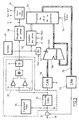
- la figure 3 est un schéma descriptif des différents circuits et modules d'un mode de réalisation préférentiel du dispositif selon l'invention fonctionnant en mode numérique ;
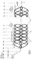
- la figure 4 est la représentation, sous forme de diagramme de l'oeil, de la forme du signal D2MAC dans la salve de données.
- FIG. 1 represents the classic diagram of an analog clamp circuit;
- Figure 2 shows schematically the structure of the D2MAC / Packet baseband signal;
- FIG. 3 is a descriptive diagram of the various circuits and modules of a preferred embodiment of the device according to the invention operating in digital mode;
- FIG. 4 is the representation, in the form of a diagram of the eye, of the form of the signal D2MAC in the burst of data.
Comme représenté en figure 2, le signal D2MAC, en bande de base est constitué, pour chaque ligne, successivement d'une salve de données 21, d'une période d'alignement 22, d'un signal de chrominance 23 et d'un signal de luminance 24.As shown in FIG. 2, the baseband signal D2MAC consists, for each line, successively of a data burst 21, an
La durée de ces différents signaux, ainsi que des périodes de transition, est la suivante :
- a =
- 208 périodes pour 105 bits de données et de synchro
- b =
- 4 périodes d'horloge pour la transition à la fin des données
- c =
- 15 périodes d'horloge - période d'alignement (0,5 V)
- d =
- 11 périodes d'horloge pour la transition pondérée vers le signal de différence de couleur
- e =
- 348 périodes d'horloge (349 échantillons) pour la composante de différence de couleur
- g =
- 6 périodes d'horloge pour la transition pondérée du signal de différence de couleur à celui de luminance
- h =
- 696 périodes d'horloge (697 échantillons) pour la composante de luminance
- j =
- 8 périodes d'horloge pour la transition pondérée à la fin du signal de luminance.
- a =
- 208 periods for 105 bits of data and sync
- b =
- 4 clock periods for the transition to the end of the data
- c =
- 15 clock periods - alignment period (0.5 V)
- d =
- 11 clock periods for the weighted transition to the color difference signal
- e =
- 348 clock periods (349 samples) for the color difference component
- g =
- 6 clock periods for the weighted transition from the color difference signal to the luminance signal
- h =
- 696 clock periods (697 samples) for the luminance component
- j =
- 8 clock periods for the weighted transition at the end of the luminance signal.
Pour une fréquence d'horloge à 20,25 MHz, la valeur de la demi-période symbole T est de 49,4 ns, ce qui donne une période symbole de 98,8 ns.For a clock frequency at 20.25 MHz, the value of the symbol half-period T is 49.4 ns, which gives a symbol period of 98.8 ns.
Selon l'invention, on exploite la salve de données 21 pour augmenter artificiellement la durée de la période d'alignement.According to the invention, the data burst 21 is used to artificially increase the duration of the alignment period.
Dans le signal D2MAC, chaque salve de données comporte un total de 105 bits. 6 bits 41 constituent le mot de synchronisation de ligne, et les 99 bits restants 42 sont utilisés pour la transmission des sons et des données organisés en paquet de 751 bits (Figure 4).In the D2MAC signal, each data burst has a total of 105 bits. 6
Dans le standard à 625 lignes, une période d'alignement 22 de 15 échantillons suit la salve numérique de toutes les lignes de 1 à 624. La fin de la salve 624 contient un mot de marquage de la position de la période d'alignement.In the 625 line standard, an
Le principe du codage duobinaire, retenu pour la salve de données, consiste à utiliser un code à trois niveaux obtenu par addition arithmétique du signal binaire (0,1) à coder, avec lui-même, retardé d'un cycle d'horloge, selon la formule.
ck = bk + bk-1,
avec
ck : valeur de codage duobinaire ;
bk : valeur du signal binaire ;
+ : addition arithmétique.The principle of duobinary coding, retained for the burst of data, consists in using a three-level code obtained by arithmetic addition of the binary signal (0,1) to be coded, with itself, delayed by a clock cycle, according to the formula.
ck = bk + bk-1,
with
ck: duobinary coding value;
bk: value of the binary signal;
+: arithmetic addition.
Le codage duobinaire présente l'avantage de compacter le contenu spectral du signal. L'opération de codage duobinaire est précédée d'une opération de précodage, permettant d'éviter les propagations d'erreurs, et de simplifier le décodage.Duobinary coding has the advantage of compacting the spectral content of the signal. The duobinary coding operation is preceded by a precoding operation, making it possible to avoid propagation of errors, and to simplify decoding.
Comme représenté en figure 4, le diagramme de l'oeil de la salve de données duobinaire permet de mettre en évidence les passages à zéro 43 du signal. Du fait du principe du signal duobinaire (1,0,-1), le signal prend la valeur zéro sur au moins la moitié des symboles duobinaires 42. C'est chacun de ces passages à zéro 43 que le procédé de restitution de la composante continue suivant l'invention exploite dans le but d'augmenter artificiellement la période d'alignement.As shown in FIG. 4, the eye diagram of the duobinary burst of data makes it possible to highlight the zero
Cette augmentation de la période d'alignement est particulièrement utile pour diminuer fortement les effets des bruits de clamp. A titre d'exemple de la sensibilité de l'oeil du spectateur de télévision aux défauts du type des bruits de clamp, on notera que les seuils de perception des défauts, ont été déterminés comme suit :

La figure 3 schématise un mode de réalisation en mode numérique d'un dispositif de restitution de la composante continue suivant l'invention.Figure 3 shows schematically an embodiment in digital mode of a device for restoring the DC component according to the invention.
Sur cette figure 3, le signal en bande de base décodé 30 est introduit dans le circuit de l'invention selon une amplitude 1 V crête-crête.In this FIG. 3, the decoded
Après passage dans un circuit soustracteur 31 dont la seconde entrée reçoit la boucle de rétroaction 32 du circuit de restitution de la composante continue, une portion du signal est prélevée en 33 pour l'acheminement vers les circuits de traitement de vidéo 34.After passing through a
Un filtre passe-bas 35 à 5 MHz assure l'élimination du bruit du signal, avant la conversion dans le convertisseur analogique-numérique 36.A low-
Le signal filtré par le filtre passe-bas 35 est également acheminé vers un circuit convertisseur duobinaire/binaire 37, qui alimente notamment un module de récupération de rythme 38 fournissant le signal d'horloge H, et un module de base de temps 39.The signal filtered by the low-
Le signal converti en binaire est également envoyé vers un module de traitement de données 40.The signal converted into binary is also sent to a
L'ensemble des circuits 34, 35, 37, 38, 39, 40, appartiennent à la chaine classique de traitement du signal DMAC à la réception.All the
Le fonctionnement du circuit additionneur est commandé par le circuit OU 51, qui est sous contrôle du signal Fen issu du circuit de base de temps 39. Ce signal Fen est une fenêtre encadrant la partie duobinaire du signal, et la période d'alignement. Il est actif à l'état bas.The operation of the adder circuit is controlled by the
Parallèlement au circuit additionneur 50, le circuit 52 de comptage des zéros est également placé, lui aussi, sous contrôle du signal Fen, ainsi que d'un signal supplémentaire RAZ de remise à zéro. Le signal RAZ est également issu du module de base de temps 39.In addition to the
On notera que le signal d'horloge H récupéré en sortie du module 38 commande également le circuit de comptage de zéro 52, ainsi que le convertisseur analogique numérique 36.It will be noted that the clock signal H recovered at the output of the
L'additionneur 50 et le compteur de zéro 52 alimentent enfin un processeur 53 de calcul de la correction de la composante continue. Le processeur 53 joue le rôle de moyenneur, en divisant la valeur cumulée obtenue dans l'additionneur 50, par le nombre de zéro comptés dans le circuit 52.The
Un signal de synchronisation de trame 54, alimentant le processeur 53, permet de tenir compte d'une information de prédiction de la dispersion d'énergie des signaux transmis en radiodiffusion par satellite. Cette prédiction est obtenue aisément du fait que la composante BF de dispersion d'énergie est synchrone de la trame.A
Le signal de correction calculé par le processeur 53 est réacheminée par la boucle de rétroaction 32 vers l'entrée du dispositif. Ce signal est converti en mode analogique dans le convertisseur numérique analogique 55, avant d'arriver en entrée du circuit soustracteur 31.The correction signal calculated by the
Le fonctionnement de ce dispositif est le suivant.The operation of this device is as follows.
Le compteur 52 est incrémenté à chaque fois qu'un zéro est présent dans le signal duobinaire 30. De son côté, la logique de commande constituée par le circuit OU 51 permet de n'activer la fonction d'addition de l'additionneur 50 que pendant la période d'émission d'une salve de données duobinaire, et uniquement lorsque le symbole émis est un zéro.The
L'additionneur 50, monté en accumulateur, totalise le cumul des niveaux continus aux instants des zéros du signal de données.The
De façon avantageuse, la période d'alignement (intervalle de clamp), ainsi que la transition entre la salve de données et la période d'alignement, sont inclus dans le processus.Advantageously, the alignment period (clamp interval), as well as the transition between the data burst and the alignment period, are included in the process.
Le compteur 52 calcule le nombre de zéros contenus dans la partie duobinaire du signal entre deux remises à zéro RAZ.The
A partir de ces informations, le processeur 53 effectue les opérations suivantes :
- une opération de division du total cumulé fourni par l'additionneur 50, par le nombre de zéro fourni par le compteur 52. Cette opération permet d'obtenir le niveau moyen de l'estimation de la composante continue ;
- une opération de filtrage de l'estimation sur plusieurs lignes. De façon avantageuse, ce filtrage peut être effectué sur au moins deux lignes, et par exemple sur six lignes consécutives. Ceci permet de limiter le bruit d'estimation ;
- une opération optionnelle de prédiction de la correction du signal de dispersion d'énergie, dans le cas d'une transmission du signal par satellite.
- an operation of dividing the cumulative total supplied by the
adder 50, by the number of zero supplied by thecounter 52. This operation makes it possible to obtain the average level of the estimate of the continuous component; - an estimation filtering operation on several lines. Advantageously, this filtering can be carried out on at least two lines, and for example on six consecutive lines. This limits the estimation noise;
- an optional operation for predicting the correction of the energy dispersion signal, in the case of a transmission of the signal by satellite.
Ce dispositif permet très efficacement de prolonger artificiellement la durée de la période d'alignement. En effet, du fait qu'une salve de données duobinaire comprend environ une centaine de symboles duobinaires, on peut donc y compter environ une cinquantaine de passages à zéro. En additionnant le nombre de bits de la période d'alignement, qui est de 15 dans le cas d'un signal D2MAC, on obtient ainsi 65 passages à zéro environ, ce qui correspond à plus qu'un quadruplement du nombre d'échantillons prélevés.This device very effectively makes it possible to artificially extend the duration of the alignment period. Indeed, because a burst of duobinary data comprises about a hundred duobinary symbols, we can therefore count about fifty zero crossings there. By adding the number of bits of the alignment period, which is 15 in the case of a D2MAC signal, this gives approximately 65 zero crossings, which corresponds to more than a quadrupling of the number of samples taken. .
D'autre part, on constate également que la durée d'observation pendant laquelle sont prélevés les échantillons de passage à zéro est d'environ 5750 ns (15x49,4ns + 50x98,8ns), soit plus de sept fois la durée de la période d'alignement.On the other hand, we also note that the duration of observation during which the zero crossing samples are taken is approximately 5750 ns (15x49.4ns + 50x98.8ns), more than seven times the duration of the alignment period.
On constate d'ailleurs qu'il serait envisageable de se passer, le cas échéant, des quinze échantillons de la période d'alignement.We note moreover that it would be conceivable to do without, if necessary, the fifteen samples of the alignment period.
De façon alternative au dispositif de la figure 3, un autre mode de réalisation de l'invention consisterait à remplacer les moyens de comptage des passages à zéro et d'accumulation des niveaux du signal, par une capacité sélectivement rechargée lors desdits instants de passages à zéro du signal duobinaire. Bien que moins performante que la version numérique, cette version analogique est tout à fait opérationnelle.As an alternative to the device of FIG. 3, another embodiment of the invention would consist in replacing the means for counting the zero crossings and for accumulating the signal levels, by a capacity selectively recharged during said instants of passages to zero of the duobinary signal. Although less efficient than the digital version, this analog version is fully operational.
Dans une application avantageuse de l'invention, ce dispositif de restitution de la composante continue peut être placé dans un régénérateur de signal, de la chaine de transmission du signal DMAC.In an advantageous application of the invention, this device for restoring the DC component can be placed in a signal regenerator, of the DMAC signal transmission chain.
Le dispositif de l'invention trouve place également aussi bien dans les stations d'émission vers des satellites-relais de diffusion, que dans des têtes de réseaux de réception, et dans les récepteurs terminaux de la chaine de transmission.The device of the invention also finds its place both in transmitting stations to broadcasting relay satellites, as in receiving network heads, and in terminal receivers of the transmission chain.
Claims (11)
- Method of restoring the reference DC component of a television source signal, of the type of the MAC/Packets family, each line being especially constituted by a time multiplex of a burst of data (21) in duobinary digital coding, of an image part (23, 24), and of an alignment period (22),
characterised in that the DC component, for each line, is restored by means of an estimate of the value of the said component produced from an operation for detection of the level of the duobinary data signal during zero crossings (43) of the said duobinary signal. - Method according to Claim 1, characterised in that the said estimate is produced by taking into account both the detection of the level of the zero crossings of the said duobinary signal (21), and the level of the signal in the said alignment period (22).
- Method according to any one of Claims 1 or 2, characterised in that the said detection of the level of the zero crossings of the said duobinary signal, is produced by detection and counting of the number of the said zero crossings (43), by accumulation of the DC levels at the instants of the said zeros, and by division of the said total by the number of zeros, so as to obtain a mean estimated level of the DC component.
- Method according to either of Claims 1 to 3, characterised in that the said estimated DC component undergoes filtering carried out over at least two consecutive lines of the source signal.
- Method according to any one of Claims 1 to 3, characterised in that it includes a step or prediction of the correction of a modulation with dispersion of energy from the source signal.
- Device for implementing the method of restoring the DC component of a source signal of the type of the MAC Packets family, according to any one of Claim 2 to 5, characterised in that it comprises:- means of counting (52) the number of zero crossings (43) of each of the said bursts of duobinary data (21),- means (50) for the accumulation of the levels of the said decoded duobinary signal at the instants of the said zero crossings (43),- means (51) for control of the activation of the said accumulation means (50),- means (53) for division of the contents of the said accumulation means (50), by the contents of the said counting means (52).
- Device according to Claim 6, characterised in that the said burst of decoded duobinary data (21) is an analog signal, and in that the said accumulation means comprise an analog digital converter (36), and an adder circuit (50), mounted as an accumulator.
- Device according to Claim 6, characterised in that the said burst of duobinary data (21) is an analog signal, and in that the said accumulation and division means are replaced by a capacitor which is selectively recharged during the said instants of zero crossings (43) by the said duobinary signal.
- Device according to Claim 6, characterised in that it comprises means (53, 54) for prediction of the correction of a modulation with dispersion of energy of the source signal.
- Signal regenerator, characterised in that it comprises a device according to any one of Claims 6 to 9.
- Use of a device according to any one of Claims 6 to 9, in an uplink transmission station for a satellite and/or in a downlink receiver network head for a signal originating from a satellite.
Applications Claiming Priority (2)
| Application Number | Priority Date | Filing Date | Title |
|---|---|---|---|
| FR8808625 | 1988-06-23 | ||
| FR8808625A FR2633473B1 (en) | 1988-06-23 | 1988-06-23 | METHOD FOR RESTORING THE CONTINUOUS COMPONENT OF A SIGNAL OF THE DMAC-PACKET TYPE, DEVICE AND USE THEREOF |
Publications (2)
| Publication Number | Publication Date |
|---|---|
| EP0348322A1 EP0348322A1 (en) | 1989-12-27 |
| EP0348322B1 true EP0348322B1 (en) | 1993-04-28 |
Family
ID=9367769
Family Applications (1)
| Application Number | Title | Priority Date | Filing Date |
|---|---|---|---|
| EP19890460021 Expired - Lifetime EP0348322B1 (en) | 1988-06-23 | 1989-06-22 | Method for the restoration of the continuous component of a dmac type signal, device therefor and use thereof |
Country Status (3)
| Country | Link |
|---|---|
| EP (1) | EP0348322B1 (en) |
| DE (1) | DE68906206T2 (en) |
| FR (1) | FR2633473B1 (en) |
Families Citing this family (3)
| Publication number | Priority date | Publication date | Assignee | Title |
|---|---|---|---|---|
| FR2661060B1 (en) * | 1990-04-11 | 1996-02-23 | Telediffusion Fse | DEVICE FOR SUPPRESSING CLAMPING NOISE FROM A RECEIVING TV SIGNAL. |
| FR2675331A1 (en) * | 1991-04-12 | 1992-10-16 | Philips Electro Grand Public | APPARATUS PROVIDED WITH AN IMPROVED DEVICE FOR REINSTALLING THE CONTINUOUS COMPONENT. |
| GB9120950D0 (en) * | 1991-10-02 | 1991-11-13 | Philips Electronic Associated | Signal clamping |
Family Cites Families (1)
| Publication number | Priority date | Publication date | Assignee | Title |
|---|---|---|---|---|
| FR2565448B1 (en) * | 1984-06-04 | 1986-10-10 | France Etat | SYNCHRONIZATION EXTRACTION METHOD AND DEVICE FOR TIME-MULTIPLEXED BROADCASTING SYSTEM OF DIGITAL AND ANALOG SIGNALS |
-
1988
- 1988-06-23 FR FR8808625A patent/FR2633473B1/en not_active Expired - Lifetime
-
1989
- 1989-06-22 EP EP19890460021 patent/EP0348322B1/en not_active Expired - Lifetime
- 1989-06-22 DE DE1989606206 patent/DE68906206T2/en not_active Expired - Fee Related
Also Published As
| Publication number | Publication date |
|---|---|
| EP0348322A1 (en) | 1989-12-27 |
| DE68906206T2 (en) | 1993-11-11 |
| FR2633473A1 (en) | 1989-12-29 |
| FR2633473B1 (en) | 1990-11-09 |
| DE68906206D1 (en) | 1993-06-03 |
Similar Documents
| Publication | Publication Date | Title |
|---|---|---|
| EP0107246B1 (en) | Receiver for a data transmission modem comprising an echo canceller and an equalizer | |
| EP0054829B1 (en) | Method and apparatus for detecting the training sequence of an autoadaptive equalizer | |
| EP0159924B1 (en) | Digital "didon" demodulator | |
| FR2623669A1 (en) | EQUALIZATION APPARATUS AND METHOD FOR DATA TRANSMISSION | |
| EP0013343B1 (en) | Process and device to detect a pseudo-random sequence of 0 degree and 180 degree phase changes of the carrier in a data receiver | |
| FR2602944A1 (en) | Subscriber unit for wireless digital telephone; modem and diverse devices (frequency synthesizer etc.) for this unit | |
| FR2533095A1 (en) | METHOD AND DEVICE FOR DEMODULATING A PHASE-MODIFIED CARRIER WAVE BY A SUB-CARRIER WAVE WHICH IS MODULATED IN PHASE DISPLACEMENT BY BASEBAND SIGNALS | |
| EP0576359B1 (en) | Method and apparatus for decision feedback equalisation for the block transmission of information symbols | |
| US5565930A (en) | Receiver with oversampling analog-to-digital conversion for digital signals accompanied by analog TV signals | |
| EP0053958A1 (en) | Process for the parallel/series conversion of a digital parallel sequence | |
| LU82859A1 (en) | PHASE NOISE CORRECTION CIRCUIT FOR A DATA TRANSMISSION SYSTEM | |
| EP0348322B1 (en) | Method for the restoration of the continuous component of a dmac type signal, device therefor and use thereof | |
| EP0242915B1 (en) | Device for clock recovery in an information transmission system using in one transmission direction the time division multiple access principle | |
| EP0337565A1 (en) | Device for coding signals representative of a sequence of pictures and system for transmission of high definition television pictures including such a device | |
| EP0169093A1 (en) | Receiver for time division multiplexed television transmission comprising a frequency demodulator | |
| EP0368417B1 (en) | Apparatus comprising an improved device for clamp-error compensation | |
| EP3387766B1 (en) | Methods and devices for transmitting a continuous bit stream in a digital network non-synchronous with the bit stream | |
| EP0283077A1 (en) | Apparatus for decoding dual binarily coded signals | |
| FR2858730A1 (en) | Scheduling information recovering method for e.g. Ethernet network, involves using frequency or phase modulated signal for transmitting additional information to recover clock signal, and recovering clock signal using information | |
| WO2005096581A1 (en) | Cofdm demodulator with optimal fft analysis window positioning | |
| EP0295974B1 (en) | Method and device for decoding duobinary signals transmitted in bursts | |
| EP0338915B1 (en) | Method for transmitting television programmes of the mac/packet type, and device using such a method | |
| EP0296914A1 (en) | Method and television device with time division multiplex | |
| EP0328461A1 (en) | Method of broadcasting a high-definition television programme, and receiver with equalizer for receiving such a programme | |
| EP0239465A1 (en) | Device for digitally decoding television signals by means of adaptive luminance-chrominance separation means |
Legal Events
| Date | Code | Title | Description |
|---|---|---|---|
| PUAI | Public reference made under article 153(3) epc to a published international application that has entered the european phase |
Free format text: ORIGINAL CODE: 0009012 |
|
| AK | Designated contracting states |
Kind code of ref document: A1 Designated state(s): DE GB IT NL |
|
| 17P | Request for examination filed |
Effective date: 19900530 |
|
| 17Q | First examination report despatched |
Effective date: 19920729 |
|
| RAP1 | Party data changed (applicant data changed or rights of an application transferred) |
Owner name: TELEDIFFUSION DE FRANCE S.A. Owner name: FRANCE TELECOM |
|
| GRAA | (expected) grant |
Free format text: ORIGINAL CODE: 0009210 |
|
| AK | Designated contracting states |
Kind code of ref document: B1 Designated state(s): DE GB IT NL |
|
| REF | Corresponds to: |
Ref document number: 68906206 Country of ref document: DE Date of ref document: 19930603 |
|
| ITF | It: translation for a ep patent filed |
Owner name: JACOBACCI CASETTA & PERANI S.P.A. |
|
| GBT | Gb: translation of ep patent filed (gb section 77(6)(a)/1977) |
Effective date: 19930728 |
|
| PLBE | No opposition filed within time limit |
Free format text: ORIGINAL CODE: 0009261 |
|
| STAA | Information on the status of an ep patent application or granted ep patent |
Free format text: STATUS: NO OPPOSITION FILED WITHIN TIME LIMIT |
|
| 26N | No opposition filed | ||
| PGFP | Annual fee paid to national office [announced via postgrant information from national office to epo] |
Ref country code: GB Payment date: 19980526 Year of fee payment: 10 Ref country code: DE Payment date: 19980526 Year of fee payment: 10 |
|
| PGFP | Annual fee paid to national office [announced via postgrant information from national office to epo] |
Ref country code: NL Payment date: 19980531 Year of fee payment: 10 |
|
| PG25 | Lapsed in a contracting state [announced via postgrant information from national office to epo] |
Ref country code: GB Free format text: LAPSE BECAUSE OF NON-PAYMENT OF DUE FEES Effective date: 19990622 |
|
| PG25 | Lapsed in a contracting state [announced via postgrant information from national office to epo] |
Ref country code: NL Free format text: LAPSE BECAUSE OF NON-PAYMENT OF DUE FEES Effective date: 20000101 |
|
| GBPC | Gb: european patent ceased through non-payment of renewal fee |
Effective date: 19990622 |
|
| NLV4 | Nl: lapsed or anulled due to non-payment of the annual fee |
Effective date: 20000101 |
|
| PG25 | Lapsed in a contracting state [announced via postgrant information from national office to epo] |
Ref country code: DE Free format text: LAPSE BECAUSE OF NON-PAYMENT OF DUE FEES Effective date: 20000503 |
|
| PG25 | Lapsed in a contracting state [announced via postgrant information from national office to epo] |
Ref country code: IT Free format text: LAPSE BECAUSE OF NON-PAYMENT OF DUE FEES;WARNING: LAPSES OF ITALIAN PATENTS WITH EFFECTIVE DATE BEFORE 2007 MAY HAVE OCCURRED AT ANY TIME BEFORE 2007. THE CORRECT EFFECTIVE DATE MAY BE DIFFERENT FROM THE ONE RECORDED. Effective date: 20050622 |