EP0339837A2 - Electromagnetic valve - Google Patents
Electromagnetic valve Download PDFInfo
- Publication number
- EP0339837A2 EP0339837A2 EP19890303666 EP89303666A EP0339837A2 EP 0339837 A2 EP0339837 A2 EP 0339837A2 EP 19890303666 EP19890303666 EP 19890303666 EP 89303666 A EP89303666 A EP 89303666A EP 0339837 A2 EP0339837 A2 EP 0339837A2
- Authority
- EP
- European Patent Office
- Prior art keywords
- passage
- molten metal
- frequency
- coil
- discharge
- Prior art date
- Legal status (The legal status is an assumption and is not a legal conclusion. Google has not performed a legal analysis and makes no representation as to the accuracy of the status listed.)
- Granted
Links
Images

Classifications
-
- B—PERFORMING OPERATIONS; TRANSPORTING
- B22—CASTING; POWDER METALLURGY
- B22D—CASTING OF METALS; CASTING OF OTHER SUBSTANCES BY THE SAME PROCESSES OR DEVICES
- B22D39/00—Equipment for supplying molten metal in rations
- B22D39/003—Equipment for supplying molten metal in rations using electromagnetic field
-
- Y—GENERAL TAGGING OF NEW TECHNOLOGICAL DEVELOPMENTS; GENERAL TAGGING OF CROSS-SECTIONAL TECHNOLOGIES SPANNING OVER SEVERAL SECTIONS OF THE IPC; TECHNICAL SUBJECTS COVERED BY FORMER USPC CROSS-REFERENCE ART COLLECTIONS [XRACs] AND DIGESTS
- Y10—TECHNICAL SUBJECTS COVERED BY FORMER USPC
- Y10T—TECHNICAL SUBJECTS COVERED BY FORMER US CLASSIFICATION
- Y10T137/00—Fluid handling
- Y10T137/206—Flow affected by fluid contact, energy field or coanda effect [e.g., pure fluid device or system]
- Y10T137/2082—Utilizing particular fluid
-
- Y—GENERAL TAGGING OF NEW TECHNOLOGICAL DEVELOPMENTS; GENERAL TAGGING OF CROSS-SECTIONAL TECHNOLOGIES SPANNING OVER SEVERAL SECTIONS OF THE IPC; TECHNICAL SUBJECTS COVERED BY FORMER USPC CROSS-REFERENCE ART COLLECTIONS [XRACs] AND DIGESTS
- Y10—TECHNICAL SUBJECTS COVERED BY FORMER USPC
- Y10T—TECHNICAL SUBJECTS COVERED BY FORMER US CLASSIFICATION
- Y10T137/00—Fluid handling
- Y10T137/206—Flow affected by fluid contact, energy field or coanda effect [e.g., pure fluid device or system]
- Y10T137/2087—Means to cause rotational flow of fluid [e.g., vortex generator]
- Y10T137/2104—Vortex generator in interaction chamber of device
-
- Y—GENERAL TAGGING OF NEW TECHNOLOGICAL DEVELOPMENTS; GENERAL TAGGING OF CROSS-SECTIONAL TECHNOLOGIES SPANNING OVER SEVERAL SECTIONS OF THE IPC; TECHNICAL SUBJECTS COVERED BY FORMER USPC CROSS-REFERENCE ART COLLECTIONS [XRACs] AND DIGESTS
- Y10—TECHNICAL SUBJECTS COVERED BY FORMER USPC
- Y10T—TECHNICAL SUBJECTS COVERED BY FORMER US CLASSIFICATION
- Y10T137/00—Fluid handling
- Y10T137/206—Flow affected by fluid contact, energy field or coanda effect [e.g., pure fluid device or system]
- Y10T137/218—Means to regulate or vary operation of device
- Y10T137/2191—By non-fluid energy field affecting input [e.g., transducer]
Definitions
- This invention relates to an electromagnetic valve, and particularly to an electromagnetic valve for use for discharge of molten metal from a container.
- a method of controlling or preventing discharge of molten metal from a container through a discharge passage in the container below the level of the molten metal therein which comprises utilizing electromagnetic forces induced in the molten metal by an induction coil disposed around the container to move the molten metal away from the discharge passage in the container.
- an induction coil disposed around the container to move the molten metal away from the discharge passage in the container.
- a valve comprising a body providing a discharge passage through which, in use, molten metal will flow from a container under the action of gravity; an electrical induction coil located about the passage; and means to supply a high frequency electric current to the coil whereby the coil provides an alternating magnetic field which induces electric currents in molten metal in the passage, interaction between the field and the currents providing a force which urges the molten metal away from the wall of the passage towards the axis thereof.
- An electromagnetic overpressure is thus created in the molten metal in the passage, which overpressure can be used to regulate the flow of the molten metal from the container.
- the frequency f of the electric current supplied to the coil must be sufficiently high for the depth of penetration ⁇ of the magnetic field into the molten metal to satisfy the condition: ⁇ R (1) where R is the radius of the molten metal stream in the passage before it is caused to contract by the application of the electromagnetic field.
- the current state of the art teaches that the frequency of the electric current should be sufficiently high for the skin depth to be small compared with the radius of the molten metal stream in the passage.
- the metal stream diameter lies between 13 and 20 mm.
- the frequencies to satisfy the equality expressed in (3) therefore lie in the range 80 to 30 kHz.
- the frequency range is 15 to 6 kHz.
- the main interest in electromagnetic flow control valves is for the high melting point alloys, of which the ferrous alloys are the most important.
- field strengths as high as 1/3 Tesla might be needed to obtain the required degree of flow control. Currents of a few thousand amps will generally be needed to generate such field strengths. This combination of high current and high frequency poses a difficult electrical engineering problem.
- the induction coils used are small and have inductances of only a few microhenries, while matching transformers cannot be placed close to the molten metal stream. Thus, a low inductance bus-bar must generally be used to supply the electric current to the coil.
- a further problem, resulting from the high frequencies required, is that the power dissipated in the coil and the molten metal stream can become very large.
- the passage has a first portion of radius R B adjacent the container and a second portion of smaller radius R E extending from the first portion to the free end of the passage.
- the invention provides an electromagnetic valve which allows the frequency of the electric current supplied to the coil to be chosen independently of the passage exit diameter.
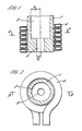
- the valve shown in Figures 1 and 2 has a body 1 of refractory material providing a discharge passage 2, 3 through which in use, molten metal will flow from a container (not shown) under the action of gravity.
- the passage has a first portion 2 of radius R B adjacent the container, and a second portion 3 of smaller radius R E extending from the first portion 2 to the free discharge end of the passage.
- a water cooled copper coil 4 surrounds the passage 2, 3, the mid plane of the coil 4 being level with the junction between passage portions 2 and 3.
- an alternating magnetic field of peak amplitude B is set up at the circumference of the molten metal in the passage portion 2.
- the field decays as the centre of the molten metal stream is approached, and for sufficiently high frequencies is essentially zero over the central portion of the stream.
- the induced circumferential currents have a similar distribution with the maximum current density around the outer circumference of the molten metal stream in the passage portion 2.
- Interaction between the induced current and the field B gives rise to an electromagnetic force directed radially towards the centre of the stream, which is a maximum at the outer circumference of the passage portion 2, and decays to zero over the central portion.
- An overpressure is therefore created in the central portion of the stream which is equal to the integral of the electromagnetic force along a radius. For the conditions prevailing in the present embodiment this overpressure is approximately B2/2 ⁇ .
- condition (5) can be simplified to:
- the radius R B of the passage portion 2 was 17 mm and the radius R E of the passage portion 3 was 6.5 mm.
- Flow rates ⁇ were measured for different metal depths h and values of the field B. These values were non-dimensionalised by the flow rate ⁇ o for zero field and the same metal depth. The square of this ratio ( ⁇ / ⁇ o )2 is plotted against B2/2 ⁇ gh in Figure 3. For values of B2/2 ⁇ gh up to 0.3 the flow rate increases by approximately 10% and the stream is observed to increase in diameter.
Landscapes
- Physics & Mathematics (AREA)
- Electromagnetism (AREA)
- Engineering & Computer Science (AREA)
- Mechanical Engineering (AREA)
- Magnetically Actuated Valves (AREA)
- Continuous Casting (AREA)
- Valve Device For Special Equipments (AREA)
- Crucibles And Fluidized-Bed Furnaces (AREA)
- Reciprocating, Oscillating Or Vibrating Motors (AREA)
Abstract
Description
- This invention relates to an electromagnetic valve, and particularly to an electromagnetic valve for use for discharge of molten metal from a container.
- In GB-A-777213 there is disclosed a method of controlling or preventing discharge of molten metal from a container through a discharge passage in the container below the level of the molten metal therein, which comprises utilizing electromagnetic forces induced in the molten metal by an induction coil disposed around the container to move the molten metal away from the discharge passage in the container. When the coil is not energized the molten metal flows out of the container through the discharge passage under the action of gravity, but when the coil is energized the molten metal is moved away from the discharge passage and there is no outflow.
- When the magnetic field is applied to drive the metal away from the discharge passage an air/metal interface is formed. As the denser molten metal is above the air this free surface is inherently unstable. The surface tension and density of the molten metal, plus the magnitude and frequency of the applied magnetic field, determine the maximum extent of the surface for which it remains stable. Typically the maximum dimension of the free surface cannot exceed more than a few tens of millimetres, and this imposes a maximum size on the discharge passage to order to achieve the maximum flow rate required while retaining the ability to shut off the flow by applying the magnetic field.
- In FR-A-2316026 there is disclosed such a valve comprising a body providing a discharge passage through which, in use, molten metal will flow from a container under the action of gravity; an electrical induction coil located about the passage; and means to supply a high frequency electric current to the coil whereby the coil provides an alternating magnetic field which induces electric currents in molten metal in the passage, interaction between the field and the currents providing a force which urges the molten metal away from the wall of the passage towards the axis thereof. An electromagnetic overpressure is thus created in the molten metal in the passage, which overpressure can be used to regulate the flow of the molten metal from the container.
- In this document it is stated that the frequency f of the electric current supplied to the coil must be sufficiently high for the depth of penetration δ of the magnetic field into the molten metal to satisfy the condition:
δ<R (1)
where R is the radius of the molten metal stream in the passage before it is caused to contract by the application of the electromagnetic field. - The relationship between the frequency and skin depth is δ = )
1/fπµσ from which it follows that:-
- Tests show that to achieve efficient flow control the skin depth δ should be equal to or less than 1/3 of the radius R of the molten metal stream in the passage:

- To summarise, the current state of the art teaches that the frequency of the electric current should be sufficiently high for the skin depth to be small compared with the radius of the molten metal stream in the passage.
- For the vast majority of molten metal discharge operations, the metal stream diameter lies between 13 and 20 mm. For ferrous alloys, for example, the frequencies to satisfy the equality expressed in (3) therefore lie in the range 80 to 30 kHz. For non-ferrous metals, such as aluminium for example the frequency range is 15 to 6 kHz. The main interest in electromagnetic flow control valves is for the high melting point alloys, of which the ferrous alloys are the most important. For these alloys, field strengths as high as 1/3 Tesla might be needed to obtain the required degree of flow control. Currents of a few thousand amps will generally be needed to generate such field strengths. This combination of high current and high frequency poses a difficult electrical engineering problem. The induction coils used are small and have inductances of only a few microhenries, while matching transformers cannot be placed close to the molten metal stream. Thus, a low inductance bus-bar must generally be used to supply the electric current to the coil. A further problem, resulting from the high frequencies required, is that the power dissipated in the coil and the molten metal stream can become very large.
- According to this invention, in an electromagnetic valve as set out above the passage has a first portion of radius RB adjacent the container and a second portion of smaller radius RE extending from the first portion to the free end of the passage.
- The invention provides an electromagnetic valve which allows the frequency of the electric current supplied to the coil to be chosen independently of the passage exit diameter.
- This invention will now be described by way of example with reference to the drawings, in which:-
- Figure 1 is a vertical sectional view on the line B-B in Figure 2 of part of the discharge passage of a valve according to the invention;
- Figure 2 is a horizontal sectional view on the line A-A in Figure 1; and
- Figure 3 is a graph illustrating operation of the valve of Figures 1 and 2.
- The valve shown in Figures 1 and 2 has a body 1 of refractory material providing a
discharge passage 2, 3 through which in use, molten metal will flow from a container (not shown) under the action of gravity. The passage has afirst portion 2 of radius RB adjacent the container, and a second portion 3 of smaller radius RE extending from thefirst portion 2 to the free discharge end of the passage. - A water cooled copper coil 4 surrounds the
passage 2, 3, the mid plane of the coil 4 being level with the junction betweenpassage portions 2 and 3. - When an alternating electric current is supplied in known manner to the coil 4 an alternating magnetic field of peak amplitude B is set up at the circumference of the molten metal in the
passage portion 2. The field decays as the centre of the molten metal stream is approached, and for sufficiently high frequencies is essentially zero over the central portion of the stream. The induced circumferential currents have a similar distribution with the maximum current density around the outer circumference of the molten metal stream in thepassage portion 2. Interaction between the induced current and the field B gives rise to an electromagnetic force directed radially towards the centre of the stream, which is a maximum at the outer circumference of thepassage portion 2, and decays to zero over the central portion. An overpressure is therefore created in the central portion of the stream which is equal to the integral of the electromagnetic force along a radius. For the conditions prevailing in the present embodiment this overpressure is approximately B²/2µ. - For a stream of fluid, such as the molten metal flowing through the
passage 2, 3 there is a relationship between velocity and pressure, known as Bernoulli's equation, such that if the pressure increases the velocity decreases. By the proper selection of the frequency of the electric current supplied to the coil 4, RB and RE, the electromagnetic forces create an overpressure B²/2µ across the top of the passage portion 3. Thus, the velocity at this position is reduced from Uo for zero field, to U for a field B, where:-
passage 2, 3, and g is acceleration due to gravity. - From the above discussion it is clear that to obtain the maximum degree of control of the flow rate through the
passage 2, 3 the overpressure B²/2µ must be developed over the whole of the passage portion 3. As this overpressure arises from the integrated affect of the electromagnetic forces along a radius between RB and RE, for maximum efficiency, the electromagnetic force should have decayed to essentially zero over the distance RB- RE measured in from the edge of the molten metal stream. For this to be so, the frequency f must be sufficiently high, and therefore the skin depth δ be sufficiently small, for the field B, and induced currents, to decay to essentially zero over this same distance RB - RE. For practical purposes it will normally be sufficient to make the skin depth δ equal to 1/3 of RB - RE and hence the frequency is given by:-
- When RB is significantly larger than RE condition (5) can be simplified to:

- Other factors to be considered when selecting the frequency normally outweigh the slight loss of efficiency in satisfying equation (6) rather than equation (5).
- Several assumptions are made in deriving equation (4). In particular, it is assumed that the electromagnetic forces do not modify the shape of the streamlines, that is to say, the discharge coefficient for the passage remains unchanged. In so far as this assumption holds true, the ratio of the velocities across the top of the passage portion 3 is the same as the ratio of the mass flows through the nozzle.

- In a particular valve in accordance with the invention the radius RB of the
passage portion 2 was 17 mm and the radius RE of the passage portion 3 was 6.5 mm. The valve was tested using aluminium and a frequency of 2.14 kHz. Under these conditions RB/δ = 3 and condition (6) is satisfied. Flow rates ṁ were measured for different metal depths h and values of the field B. These values were non-dimensionalised by the flow rate ṁo for zero field and the same metal depth. The square of this ratio (ṁ/ṁo)² is plotted against B²/2µρgh in Figure 3. For values of B²/2µρgh up to 0.3 the flow rate increases by approximately 10% and the stream is observed to increase in diameter. This is a consequence of the electromagnetic forces modifying the shape of the streamlines and hence improving the discharge coefficient of the valve. For larger values of B²/2µρgh the flow rate decreased, tending towards the theoretical performance predicted by equation (7). For the example illustrated the flow rate can be varied between 110% and 30% of the flow rate for zero field strength.
Claims (4)


Priority Applications (1)
| Application Number | Priority Date | Filing Date | Title |
|---|---|---|---|
| AT89303666T ATE85918T1 (en) | 1988-04-25 | 1989-04-13 | ELECTROMAGNETIC VALVE. |
Applications Claiming Priority (2)
| Application Number | Priority Date | Filing Date | Title |
|---|---|---|---|
| GB8809693A GB2218019B (en) | 1988-04-25 | 1988-04-25 | Electromagnetic valve |
| GB8809693 | 1988-04-25 |
Publications (3)
| Publication Number | Publication Date |
|---|---|
| EP0339837A2 true EP0339837A2 (en) | 1989-11-02 |
| EP0339837A3 EP0339837A3 (en) | 1990-12-05 |
| EP0339837B1 EP0339837B1 (en) | 1993-02-24 |
Family
ID=10635771
Family Applications (1)
| Application Number | Title | Priority Date | Filing Date |
|---|---|---|---|
| EP19890303666 Expired - Lifetime EP0339837B1 (en) | 1988-04-25 | 1989-04-13 | Electromagnetic valve |
Country Status (7)
| Country | Link |
|---|---|
| US (1) | US4947895A (en) |
| EP (1) | EP0339837B1 (en) |
| JP (1) | JPH0221084A (en) |
| AT (1) | ATE85918T1 (en) |
| DE (1) | DE68904977T2 (en) |
| ES (1) | ES2038407T3 (en) |
| GB (1) | GB2218019B (en) |
Cited By (1)
| Publication number | Priority date | Publication date | Assignee | Title |
|---|---|---|---|---|
| CN1068536C (en) * | 1995-08-28 | 2001-07-18 | 迪迪尔工厂股份公司 | Working method for inductor block, and the inductor block using the method therefor |
Families Citing this family (12)
| Publication number | Priority date | Publication date | Assignee | Title |
|---|---|---|---|---|
| FR2647874B1 (en) * | 1989-06-02 | 1991-09-20 | Galva Lorraine | ELECTROMAGNETIC VALVE FOR CONTROLLING THE FLOW OF A METAL OR METAL ALLOY IN LIQUID PHASE IN A LOADED PIPING |
| DZ1422A1 (en) * | 1989-06-09 | 2004-09-13 | Galva Lorraine | Method, procedure and installation for the continuous / intermittent coating of objects by passing said objects through a liquid mass of a coating product. |
| US5137045A (en) * | 1991-10-31 | 1992-08-11 | Inland Steel Company | Electromagnetic metering of molten metal |
| US5235954A (en) * | 1992-07-09 | 1993-08-17 | Anatoly Sverdlin | Integrated automated fuel system for internal combustion engines |
| US5350159A (en) * | 1993-02-18 | 1994-09-27 | Westinghouse Electric Corporation | On/off valve apparatus for use in conjunction with electromagnetic flow control device controlling the flow of liquid metal through an orifice |
| US5398726A (en) * | 1993-03-05 | 1995-03-21 | Sussman; Arthur | Pressure noise suppression valve |
| DE19603317A1 (en) * | 1995-08-28 | 1997-03-06 | Didier Werke Ag | Method for operating an inductor and inductor for carrying out the method |
| US6043472A (en) | 1996-08-28 | 2000-03-28 | Didier-Werke Ag | Assembly of tapping device and inductor therefor |
| GB2312861B (en) * | 1996-05-08 | 1999-08-04 | Keith Richard Whittington | Valves |
| US6321766B1 (en) | 1997-02-11 | 2001-11-27 | Richard D. Nathenson | Electromagnetic flow control valve for a liquid metal with built-in flow measurement |
| US6044858A (en) * | 1997-02-11 | 2000-04-04 | Concept Engineering Group, Inc. | Electromagnetic flow control valve for a liquid metal |
| DE102008037259A1 (en) * | 2008-08-08 | 2010-02-25 | Doncasters Precision Castings-Bochum Gmbh | Electromagnetic plug |
Citations (4)
| Publication number | Priority date | Publication date | Assignee | Title |
|---|---|---|---|---|
| GB777213A (en) * | 1952-04-09 | 1957-06-19 | Birlec Ltd | A new or improved method of, and apparatus for, controlling or preventing the discharge of molten metal from containers |
| FR2316026A1 (en) * | 1975-07-04 | 1977-01-28 | Anvar | ELECTROMAGNETIC DEVICE FOR CONTAINING LIQUID METALS |
| US4324266A (en) * | 1979-05-31 | 1982-04-13 | Agence Nationale De Valorisation De Le Recherche (Anvar) | Process and device for confining liquid metals by use of an electromagnetic field |
| EP0155575A1 (en) * | 1984-03-07 | 1985-09-25 | Concast Standard Ag | Method of regulating the flow of an electrically conductive fluid especially of a molten bath of metal in continuous casting and an apparatus for carrying out the method |
Family Cites Families (5)
| Publication number | Priority date | Publication date | Assignee | Title |
|---|---|---|---|---|
| US3520316A (en) * | 1963-12-12 | 1970-07-14 | Bowles Eng Corp | Pressure-to-pressure transducer |
| US3701357A (en) * | 1968-09-30 | 1972-10-31 | Asea Ab | Electromagnetic valve means for tapping molten metal |
| GB1348331A (en) * | 1972-01-24 | 1974-03-13 | Ass Elect Ind | Production of a stream of molten metal |
| GB1481301A (en) * | 1973-07-16 | 1977-07-27 | Bicc Ltd | Method of and apparatus for casting metals |
| GB8711041D0 (en) * | 1987-05-11 | 1987-06-17 | Electricity Council | Electromagnetic valve |
-
1988
- 1988-04-25 GB GB8809693A patent/GB2218019B/en not_active Expired - Fee Related
-
1989
- 1989-04-13 AT AT89303666T patent/ATE85918T1/en not_active IP Right Cessation
- 1989-04-13 DE DE1989604977 patent/DE68904977T2/en not_active Expired - Fee Related
- 1989-04-13 ES ES89303666T patent/ES2038407T3/en not_active Expired - Lifetime
- 1989-04-13 EP EP19890303666 patent/EP0339837B1/en not_active Expired - Lifetime
- 1989-04-21 US US07/341,780 patent/US4947895A/en not_active Expired - Fee Related
- 1989-04-25 JP JP1105721A patent/JPH0221084A/en active Pending
Patent Citations (4)
| Publication number | Priority date | Publication date | Assignee | Title |
|---|---|---|---|---|
| GB777213A (en) * | 1952-04-09 | 1957-06-19 | Birlec Ltd | A new or improved method of, and apparatus for, controlling or preventing the discharge of molten metal from containers |
| FR2316026A1 (en) * | 1975-07-04 | 1977-01-28 | Anvar | ELECTROMAGNETIC DEVICE FOR CONTAINING LIQUID METALS |
| US4324266A (en) * | 1979-05-31 | 1982-04-13 | Agence Nationale De Valorisation De Le Recherche (Anvar) | Process and device for confining liquid metals by use of an electromagnetic field |
| EP0155575A1 (en) * | 1984-03-07 | 1985-09-25 | Concast Standard Ag | Method of regulating the flow of an electrically conductive fluid especially of a molten bath of metal in continuous casting and an apparatus for carrying out the method |
Cited By (1)
| Publication number | Priority date | Publication date | Assignee | Title |
|---|---|---|---|---|
| CN1068536C (en) * | 1995-08-28 | 2001-07-18 | 迪迪尔工厂股份公司 | Working method for inductor block, and the inductor block using the method therefor |
Also Published As
| Publication number | Publication date |
|---|---|
| EP0339837A3 (en) | 1990-12-05 |
| DE68904977T2 (en) | 1993-09-09 |
| DE68904977D1 (en) | 1993-04-01 |
| GB2218019A (en) | 1989-11-08 |
| EP0339837B1 (en) | 1993-02-24 |
| ES2038407T3 (en) | 1993-07-16 |
| GB2218019B (en) | 1992-01-08 |
| ATE85918T1 (en) | 1993-03-15 |
| JPH0221084A (en) | 1990-01-24 |
| GB8809693D0 (en) | 1988-06-02 |
| US4947895A (en) | 1990-08-14 |
Similar Documents
| Publication | Publication Date | Title |
|---|---|---|
| EP0339837B1 (en) | Electromagnetic valve | |
| EP0291289B1 (en) | Electromagnetic valve | |
| ATE32500T1 (en) | METHOD FOR CONTROLLING THE FLOW OF AN ELECTRICALLY CONDUCTIVE LIQUID, ESPECIALLY METAL IN CONTINUOUS CASTING, AND AN APPARATUS FOR CARRYING OUT THE METHOD. | |
| US4143532A (en) | Inductor for forming metals by the pressure of a pulsed magnetic field | |
| US5074532A (en) | Electro-magnetic nozzle device for controlling a stream of liquid metal tapped from a crucible | |
| EP2216111A1 (en) | Electromagnetic coil device for use of in-mold molten steel capable of serving both as electromagnetic stir and electromagnetic brake | |
| US20060124272A1 (en) | Continuous casting installation for the electromagnetic rotation of molten metal moving inside the nozzle | |
| US5528620A (en) | Levitating and melting apparatus and method of operating the same | |
| EP1021574B1 (en) | Apparatus and method for stirring molten metal using electromagnetic field | |
| EP2218528B1 (en) | Electromagnetic coil device for use of in-mold molten steel capable of serving both as electromagnetic stir and electromagnetic brake | |
| RU2091192C1 (en) | Method and apparatus for preventing molten metal from penetration through vertical gap between two horizontal members | |
| US6321766B1 (en) | Electromagnetic flow control valve for a liquid metal with built-in flow measurement | |
| WO1997041985A1 (en) | Electromagnetic valve | |
| WO2000071761A8 (en) | Electromagnetic braking process in the outlet channel of a furnace | |
| JPH0428460A (en) | Apparatus and method for preventing molten metal vortex flow | |
| Suh et al. | Suppression of the vortex in ladle by static magnetic field | |
| Zimmels et al. | Principles of high-gradient magnetogravimetric separation | |
| US4446909A (en) | Process and apparatus for electromagnetic casting of multiple strands having individual head control | |
| JP2008513214A (en) | Method and equipment for suppressing vortices generated in a tundish or ladle during the respective discharge of the tundish or ladle | |
| KR970007154B1 (en) | Back flow method of molten metal with vaccum degasification device | |
| EP0058899B1 (en) | A process and apparatus for electromagnetic casting of multiple strands having individual head control | |
| SU782951A1 (en) | Method of continuous casting of metals | |
| US5601140A (en) | Apparatus for efficient sidewall containment of molten metal with horizontal alternating magnetic fields utilizing a ferromagnetic dam | |
| US5513692A (en) | Electromagnetic confinement of molten metal with conduction current assistance | |
| RU2160653C2 (en) | Apparatus for electromagnetic metal casting |
Legal Events
| Date | Code | Title | Description |
|---|---|---|---|
| PUAI | Public reference made under article 153(3) epc to a published international application that has entered the european phase |
Free format text: ORIGINAL CODE: 0009012 |
|
| AK | Designated contracting states |
Kind code of ref document: A2 Designated state(s): AT BE CH DE ES FR GB GR IT LI LU NL SE |
|
| PUAL | Search report despatched |
Free format text: ORIGINAL CODE: 0009013 |
|
| AK | Designated contracting states |
Kind code of ref document: A3 Designated state(s): AT BE CH DE ES FR GB GR IT LI LU NL SE |
|
| 17P | Request for examination filed |
Effective date: 19910104 |
|
| 17Q | First examination report despatched |
Effective date: 19920513 |
|
| RAP1 | Party data changed (applicant data changed or rights of an application transferred) |
Owner name: ELECTRICITY ASSOCIATION SERVICES LIMITED |
|
| GRAA | (expected) grant |
Free format text: ORIGINAL CODE: 0009210 |
|
| AK | Designated contracting states |
Kind code of ref document: B1 Designated state(s): AT BE CH DE ES FR GR IT LI LU NL SE |
|
| PG25 | Lapsed in a contracting state [announced via postgrant information from national office to epo] |
Ref country code: SE Effective date: 19930224 Ref country code: LI Effective date: 19930224 Ref country code: GR Free format text: LAPSE BECAUSE OF FAILURE TO SUBMIT A TRANSLATION OF THE DESCRIPTION OR TO PAY THE FEE WITHIN THE PRESCRIBED TIME-LIMIT Effective date: 19930224 Ref country code: CH Effective date: 19930224 Ref country code: AT Effective date: 19930224 |
|
| REF | Corresponds to: |
Ref document number: 85918 Country of ref document: AT Date of ref document: 19930315 Kind code of ref document: T |
|
| ITF | It: translation for a ep patent filed |
Owner name: STUDIO TORTA SOCIETA' SEMPLICE |
|
| PGFP | Annual fee paid to national office [announced via postgrant information from national office to epo] |
Ref country code: BE Payment date: 19930323 Year of fee payment: 5 |
|
| REF | Corresponds to: |
Ref document number: 68904977 Country of ref document: DE Date of ref document: 19930401 |
|
| PGFP | Annual fee paid to national office [announced via postgrant information from national office to epo] |
Ref country code: ES Payment date: 19930407 Year of fee payment: 5 |
|
| PGFP | Annual fee paid to national office [announced via postgrant information from national office to epo] |
Ref country code: FR Payment date: 19930429 Year of fee payment: 5 |
|
| ET | Fr: translation filed | ||
| PG25 | Lapsed in a contracting state [announced via postgrant information from national office to epo] |
Ref country code: LU Free format text: LAPSE BECAUSE OF NON-PAYMENT OF DUE FEES Effective date: 19930430 |
|
| PGFP | Annual fee paid to national office [announced via postgrant information from national office to epo] |
Ref country code: NL Payment date: 19930430 Year of fee payment: 5 |
|
| REG | Reference to a national code |
Ref country code: CH Ref legal event code: PL |
|
| PGFP | Annual fee paid to national office [announced via postgrant information from national office to epo] |
Ref country code: DE Payment date: 19930623 Year of fee payment: 5 |
|
| REG | Reference to a national code |
Ref country code: ES Ref legal event code: FG2A Ref document number: 2038407 Country of ref document: ES Kind code of ref document: T3 |
|
| PLBE | No opposition filed within time limit |
Free format text: ORIGINAL CODE: 0009261 |
|
| STAA | Information on the status of an ep patent application or granted ep patent |
Free format text: STATUS: NO OPPOSITION FILED WITHIN TIME LIMIT |
|
| 26N | No opposition filed | ||
| PG25 | Lapsed in a contracting state [announced via postgrant information from national office to epo] |
Ref country code: ES Free format text: LAPSE BECAUSE OF NON-PAYMENT OF DUE FEES Effective date: 19940414 |
|
| PG25 | Lapsed in a contracting state [announced via postgrant information from national office to epo] |
Ref country code: BE Effective date: 19940430 |
|
| BERE | Be: lapsed |
Owner name: ELECTRICITY ASSOCIATION SERVICES LTD Effective date: 19940430 |
|
| PG25 | Lapsed in a contracting state [announced via postgrant information from national office to epo] |
Ref country code: NL Effective date: 19941101 |
|
| NLV4 | Nl: lapsed or anulled due to non-payment of the annual fee | ||
| PG25 | Lapsed in a contracting state [announced via postgrant information from national office to epo] |
Ref country code: FR Effective date: 19941229 |
|
| PG25 | Lapsed in a contracting state [announced via postgrant information from national office to epo] |
Ref country code: DE Effective date: 19950103 |
|
| REG | Reference to a national code |
Ref country code: FR Ref legal event code: ST |
|
| REG | Reference to a national code |
Ref country code: ES Ref legal event code: FD2A Effective date: 19990301 |
|
| PG25 | Lapsed in a contracting state [announced via postgrant information from national office to epo] |
Ref country code: IT Free format text: LAPSE BECAUSE OF NON-PAYMENT OF DUE FEES;WARNING: LAPSES OF ITALIAN PATENTS WITH EFFECTIVE DATE BEFORE 2007 MAY HAVE OCCURRED AT ANY TIME BEFORE 2007. THE CORRECT EFFECTIVE DATE MAY BE DIFFERENT FROM THE ONE RECORDED. Effective date: 20050413 |