EP0338542B1 - A current and/or voltage detector for a distribution system - Google Patents
A current and/or voltage detector for a distribution system Download PDFInfo
- Publication number
- EP0338542B1 EP0338542B1 EP89107063A EP89107063A EP0338542B1 EP 0338542 B1 EP0338542 B1 EP 0338542B1 EP 89107063 A EP89107063 A EP 89107063A EP 89107063 A EP89107063 A EP 89107063A EP 0338542 B1 EP0338542 B1 EP 0338542B1
- Authority
- EP
- European Patent Office
- Prior art keywords
- receiving portion
- current sensor
- receiving
- current
- voltage
- Prior art date
- Legal status (The legal status is an assumption and is not a legal conclusion. Google has not performed a legal analysis and makes no representation as to the accuracy of the status listed.)
- Expired - Lifetime
Links
Images


Classifications
-
- G—PHYSICS
- G01—MEASURING; TESTING
- G01R—MEASURING ELECTRIC VARIABLES; MEASURING MAGNETIC VARIABLES
- G01R19/00—Arrangements for measuring currents or voltages or for indicating presence or sign thereof
-
- G—PHYSICS
- G01—MEASURING; TESTING
- G01R—MEASURING ELECTRIC VARIABLES; MEASURING MAGNETIC VARIABLES
- G01R15/00—Details of measuring arrangements of the types provided for in groups G01R17/00 - G01R29/00, G01R33/00 - G01R33/26 or G01R35/00
- G01R15/14—Adaptations providing voltage or current isolation, e.g. for high-voltage or high-current networks
- G01R15/24—Adaptations providing voltage or current isolation, e.g. for high-voltage or high-current networks using light-modulating devices
-
- G—PHYSICS
- G01—MEASURING; TESTING
- G01R—MEASURING ELECTRIC VARIABLES; MEASURING MAGNETIC VARIABLES
- G01R15/00—Details of measuring arrangements of the types provided for in groups G01R17/00 - G01R29/00, G01R33/00 - G01R33/26 or G01R35/00
- G01R15/14—Adaptations providing voltage or current isolation, e.g. for high-voltage or high-current networks
- G01R15/142—Arrangements for simultaneous measurements of several parameters employing techniques covered by groups G01R15/14 - G01R15/26
-
- H—ELECTRICITY
- H04—ELECTRIC COMMUNICATION TECHNIQUE
- H04M—TELEPHONIC COMMUNICATION
- H04M1/00—Substation equipment, e.g. for use by subscribers
- H04M1/26—Devices for calling a subscriber
Landscapes
- Physics & Mathematics (AREA)
- General Physics & Mathematics (AREA)
- Engineering & Computer Science (AREA)
- Signal Processing (AREA)
- Measuring Instrument Details And Bridges, And Automatic Balancing Devices (AREA)
Description
- This invention relates to a current or a current and a voltage detector for a distribution system, and, more particularly to a current or a current and a voltage detector for an aerial distribution line.
- In the modern world where even an instantaneous power failure is not allowed, it is required to always monitor the conditions of power transmission and distribution lines. It is well known in the art that the detection of various currents such as a zero-sequence current flowing through a transmission or distribution line is very useful in monitoring the condition of the line. Also, voltages of various parts of the line are beneficial in the monitoring. In order to detect such a current and/or voltage, a distribution line is provided with many detectors. An example of such detectors is a zero-sequence current transformer (hereinafter, referred to as "ZCT") which is installed in a aerial distribution line.
- A ZCT used in a three-phase transmission line comprises a ring type core through which all the three wired pass. When a ZCT is installed in an aerial three-phase distribution line, the ZCT is generally disposed in a pole line switch having a relay so that an unbalance in the currents or voltages of each phases can be detected. A conventional line switch is shown in Fig. 7, wherein a three-
phase line 71a is connected through aline switch 72 andtension insulators 73 mounted on apole 74 to another three-phase line 71b. A ZCT and relay (which are not shown) are incorporated in theline switch 72. If a fault occurs in theline 71a or 71b, the ZCT detects the zero-sequence current to actuate the relay, thereby actuating theswitch 72 to interrupt the connection between thelines 71a and 71b. - In this configuration of the ZCT, however, the three wires to which the phase voltage is applied are gathered in the window of the ZCT, resulting in that it is very difficult to insulate the wires from each other. Further, the insulation between the three wires deteriorates in the course of service or depending upon the degree of air tightness of the
line switch 72, causing an inferior reliability of the ZCT or a serious fault such as a shortcircuit between the lines. This may be supported by the fact that a relatively large number of accidents have been caused in the vicinity of a ZCT. In order to prevent a fault of this kind from arising, it is required to periodically replace the wires in a line switch with new ones. - EP-A1-0 256 207 describes a current and voltage detector for a distribution system, comprising a lower section, an upper section and a fastening means for combining the lower and upper sections into one body, and a current sensor and a voltage sensor; the lower section comprising: a first receiving portion for receiving an electric wire of the distribution system, the first receiving portion being disposed on the upper surface of the lower section; the upper section comprising: a second receiving portion for receiving the electric wire, the second receiving portion being disposed on the lower surface of the upper section to face the first receiving portion and comprising a U-shaped magnetic core.
- A second magnetic U-shaped magnetic core is provided in the lower section such that the two U-shaped magnetic cores form a ring-shaped magnetic core when the lower and upper sections are combined into one body. This rather bulky ring-shaped magnetic core has to be divided when the detector is attached to the wire. The ring-shaped magnetic core serves as the core for a winding which supplies the electrical power to associated circuits. The current sensor is a so-called Rogowski coil, that is an electromagnetic current sensor, and the voltage sensor is an electrical sensor comprising the housing and the insulated hub of the donut-shaped prior art detector.
- Although this prior art detector may probably eliminate some of the drawbacks of the above-mentioned ZCTs, it is a rather bulky and complicated device. The electromagnetic or electric current and voltage sensors, respectively, require rather complicated associated sensor electronics which are sensitive to changes of the harsh environment of power transmission lines where such detectors are used. The associated sensor electronics therefore require additional monitoring circuits, i.e. a so-called "watchdog" circuit for their proper operation. This measure adds to the complexity, and therefore costs, of this prior art detector.
- The current detector of this invention, which overcomes the above-discussed and numerous other disadvantages and deficiencies of the prior art, comprises a lower section, an upper section, a fastening means for combining said lower and upper section into one body, and a current sensor means, said lower section comprising: a first receiving portion for receiving an electric wire of the distribution system, the first receiving portion being disposed on the upper surface of the lower section; the upper section comprising: a second receiving portion for receiving the electric wire, the second receiving portion being disposed on the lower surface of the upper section to face the first receiving portion, and comprising a U-shaped magnetic core, wherein the current sensor means is an optical type current sensor means, the two end portions of the magnetic core protrude from the surface of the upper section, the lower section further comprises two recesses for receiving the two end portions of the U-shaped core when the lower and upper sections are combined into one body, and the optical type current sensor means is disposed at a position which is located whithin the gap of the U-shaped magnetic core when the lower and upper sections are combined into one body.
- The current and voltage detector of this invention, which overcomes the above-discussed and numerous other disadvantages and deficiencies of the prior art, comprises a lower section, an upper section and a fastening means for combining the lower and upper sections into one body, and a current sensor and a voltage sensor; the lower section comprising: a first receiving portion for receiving an electric wire of the distribution system, the first receiving portion being disposed on the upper surface of the lower section; the upper section comprising: a second receiving portion for receiving the electric wire, the second receiving portion being disposed on the lower surface of the upper section to face the first receiving portion, and comprises a U-shaped magnetic core, wherein the current sensor is an optical type current sensor, the voltage sensor is an optical type voltage sensor, the two end portions of the magnetic core protrude from the surface of the upper section, the lower section further comprises two recesses for receiving the two protruding end portions of the U-shaped core when the lower and upper sections are combined into one body, and the optical type current sensor is disposed at the position which is located in the gap of the U-shaped magnetic core when the lower and upper sections are combined into one body.
- In an embodiment of the invention, the position of said current sensor is adjustable.
- In a further embodiment, said current sensor has a magnetic optical sensor element which detects, using the Faraday effect, the strength of a magnetic field generated by the current flowing through the electric wire received in said first and second receiving portions.
- In a further embodiment, said upper section further comprises a further capacitive type potential divider disposed in the vicinity of said second receiving portion, said further potential divider and said potential divider of said lower section being electrically connected through a connecting means.
- In a further embodiment, said voltage sensor has a sensor element which utilizes the Pockels effect.
- In a further embodiment, at least either of the electrode area and electrode distance of said potential divider is adjustable.
- In further embodiments, an output signal of said current sensor is transmitted outside through an optical fiber or output signals of said current sensor and said voltage sensor are transmitted outside through optical fibers.
- Thus, the invention described herein makes possible the objectives of:
- (1) to provide a current or a current and a voltage detector which can be easily attached to a distribution line;
- (2) to provide a current or a current and a voltage detector which can operate stably for a long period of time without causing errors;
- (3) to provide a current or a current and a voltage detector which can be installed at any position on a distribution system;
- (4) to provide a current or a current and a voltage detector which which can be securely attached to a distribution line;
- (5) to provide a current or a current and a voltage detector which can produce optical signals, thereby enabling a monitoring system to be controlled through optical fibers; and
- (6) to provide a current or a current and a voltage detector having a sensor, the property of which can be easily adjusted.
- This invention may be better understood and its numerous objects and advantages will become apparent to those skilled in the art by reference to the accompanying drawings as follows:
- Figure 1 is a partly fragmentary perspective view of the current and voltage detector according to the invention;
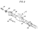
- Figure 2 is a diagram illustrating the principle of detecting a current by the detector of Fig. 1;
- Figure 3 is a diagram illustrating the principle of detecting a voltage by the detector of Fig. 1;
- Figure 4 is an exploded view of the detector of Fig. 1;
- Figure 5 is a sectional view illustrating the detector of Fig. 1 attached to a wire;
- Figure 6 is a perspective view showing the manner of attaching the detectors of Fig. 1 to a three-phase distribution line; and
- Figure 7 is a perspective view showing a manner of installing a ZCT to a three-phase distribution line.
- Figure 1 illustrates an example of the detector according to the invention. The
detector 1 of Fig. 1 is a current and voltage detector which is useful in a monitoring system for an aerial distribution line, and comprises alower section 2 and an upper section 3. Thelower section 2 incorporates anoptical current sensor 4 and anoptical voltage sensor 5. - First, the principles of detecting a current and voltage by the
sensors current sensor 4 comprises a magnetooptical element which detects the strength of a magnetic field caused by a current flowing through a wire, using the Faraday effect. With reference to Fig. 2, this will be described in more detail.Random light 42 from a light source 41 such as an LED is passed through apolarizer 43 to be changed into linearly polarizedlight 44. The linear polarizedlight 44 then impinges on a magnetooptical crystal such as a garnet (the length of which is L). In this example, a garnet containing bismuth is used as a magnetooptical crystal When amagnetic field 46 of the strength H is applied in the same direction as the propagation direction oflight 44, the plane of polarization of emittinglight 47 is rotated by an angle ϑ. The degree of the angle ϑ is detected as the light intensity by a light detector oranalyzer 48. When the transmission polarization direction of thepolarizer 43 is deviated by 45 degrees from that of theanalyzer 48, the optical output P of theanalyzer 48 is proportional to sin2ϑ. Also, the relation ϑ=VLH (wherein V is the Verdet's constant) is well known. When ϑ«1, sin(2ϑ) is approximately equal to 2ϑ, resulting in that the optical output P is proportional to the magnetic field strength H. In this way, the amount of a current flowing through a wire can be detected by optically measuring the magnetic field produced by the current around the wire. - The
optical voltage sensor 5 comprises a Pockels element. When light passes through the Pockels element, the quantity of the double refraction of the element changes in accordance with the strength of an electric field applied to the element. With reference to Fig. 3, this optical voltage detection will be described in more detail. Random light 51 from an appropriate light source (not shown) is passed through apolarizer 52 to be changed into linearpolarized light 53. The linearpolarized light 53 is then passed through a 1/4wavelength plate 54 to obtain circular polarized light 55 which is impinged onto a light detector oranalyzer 57 after passing through aPockels element 56. ThePockels element 56 is applied with a voltage 58 (e.g., the line to ground voltage of a distribution line). The form of the circular polarized light 55 changes depending upon the direction and strength of the appliedvoltage 58. Namely, as shown in fig. 3, the circular polarized light 55 may become long elliptic polarized light 59 or wide elliptic polarized light 60 in accordance with the level of the appliedvoltage 58. This causes the change in the strength of light received by theanalyzer 57. Hence, thevoltage sensor 5 can optically detect the level of the voltage applied thereto. - In the detector of Fig. 1, a
U-shaped core 6 and first and secondpotential dividers magnetic field 46 and for obtaining thevoltage 58, respectively. The first and secondpotential dividers electrodes - Referring to Figs. 1, 4 and 5, the structure of the lower and
upper sections 2 and 3 will be described in more detail. Thelower section 2 has an elongatedresin case 2a. Thecase 2a has a rectangular upper surface 2b, ahollow space 2c and anopening 2d. In thespace 2c, the opticalcurrent sensor 4, theoptical voltage sensor 5 and the firstpotential divider 7 are disposed. Thecase 2a is hermetically sealed by acover 2e which is bolted to theopening 2d. On the upper surface 2b, asemicircular groove 2f elongates along the central axis of the surface 2b. - The upper section 3 is formed by the resin molding, and has a semicylindrical shape with a rectangular
lower surface 3a. The shape of thelower surface 3a substantially corresponds to that of the upper surface 2b. Another semicircular groove 3b is formed in such a manner that the groove 3b cooperates with thegroove 2f of thelower section 2 to form a cylindrical space for receiving adistribution wire 9. The secondpotential divider 8 is disposed along the groove 3b at one end region of the upper section 3. The U-shapedmagnetic core 6 is formed at the other end region of the upper section 3, and substantially encircles the groove 3b. The two ends 6a and 6b of thecore 6 protrude from thelower face 3a. When the lower andupper sections 2 and 3 are combined to each other, the twoends 6a and 6b can be inserted into tworecesses 2 g and 2h formed on the upper surface 2b of thelower section 2, respectively, so that the opticalcurrent sensor 4 is positioned in the gap of thecore 6. - From one side of the upper section 3, two
arms 10 having ahole 10a are extended. Thearms 10 are arranged along the direction of the groove 3b,and are slidably and rotatably attached to thelower section 2 bypins 11, so that thedevice 1 can be split into the lower andupper sections 2 and 3 while preventing the twosections 2 and 3 from being completely separated, as shown in Fig. 1. This allows the easy attachment of the present device to adistribution wire 9. - The
lower section 2 is provided with amember 12 having aoval hole 12a. On the other hand, the upper section has ahook 13 having arectangular head 13a. When the lower andupper sections 2 and 3 are to be combined into one body, thehook 13 is inserted into thehole 12a, and thehead 13a is twisted to temporarily fasten the twosections 2 and 3 together. Thelower section 2 is provided with sixbolts 14 protruding from the upper surface 2b. On thelower surface 3a of the upper section 3, six threadedholes 15 are formed at the positions corresponding to those of thebolts 14. - The corresponding
electrodes potential dividers terminals 20 on the upper surface 2b, when thesections 2 and 3 are combined. - In this example, the
current sensor 4 is fixed on thevoltage sensor 5. The combination of thesensors case 2a in an adjustable manner, enabling the adjustment of the relative positional relationship between thecurrent sensor 4 and the gap of thecore 6. - In order to compensate the scattering in the properties of optical current sensors or voltage sensors among detectors, the strength of the
magnetic field 46 or the level of the appliedvoltage 58 can be adjusted. It is preferable that, when manufacturing thedetector 1, the detector is attached to an electric wire through which a predetermined level of current is flowing, and the position of the combination of thesensors current sensor 4 accurately corresponding to the current level. After the positional adjustment, the combination of thesensors case 2a by an adhesive agent so that thecurrent sensor 4 does not move. Alternatively, thecase 2a may have a recess in which the combination of the sensors can be easily fixed in a predetermined position. In order to finely adjust the position of thecurrent sensor 4, thin polyethylene plates (e.g., about 0.2mm) may be used. The level of the voltage applied to thevoltage sensor 5, i.e., the output voltage of thepotential divider 7 can be adjusted by changing the position and/or area of theelectrode potential divider 7 may be installed in thecase 2a without being resin-molded. After theoptical sensor 4 is fixed and the properties of thepotential divider 7 is adjusted as described later, a gum-like resin material such as urethane resin may be poured into thecase 2a to enhance the seal of thelower section 2. - In this example, the
potential dividers upper sections 2 and 3, respectively, and the corresponding electrodes of the two dividers are electrically connected to each other, thereby allowing the reduction of the length of the dividers along thewire 9. - The signals output from the current and
voltage sensors optical fiber cable 17. - The
detector 1 can be attached to thewire 9 in the following manner. Thelower section 2 is positioned so that thewire 9 is received in thegroove 2f, and thereafter the upper section 3 is placed over thelower section 2 so that thewire 9 is received in the cylindrical space formed by thegrooves 2f and 3b. Thehook 13 is engaged with themember 12 to temporarily fasten the twosections 2 and 3 with each other. Then, thebolts 14 are rotated to engage with the threadedholes 15, thereby securely attaching thedetector 1 to thewire 9 while firmly combining the lower andupper sections 2 and 3. This state is diagrammatically illustrated in Fig. 5. - Figure 6 illustrates an example of attaching the
detector 1 to an aerial three-phase distribution line. In the example of fig. 6, onedetector 1 is attached to each of thewires 9 of the three-phase line. Thedetectors 1 can be positioned at either side of theline switch 72, so that the side of the line the condition of which is to be monitored can be freely selected. The optical signals of thedetectors 1 are transmitted via theoptical cables 17 to thecontrol device 16 in which the signals are processed to obtain signals useful for monitoring the conditions of the distribution line (for example, a zero-sequence current). The output of thecontrol device 16 is supplied to theline switch 72 to operate it, and also supplied to a substation through acommunication line 18. The electric power for thedetectors 1 andcontrol device 16 is supplied through apower line 19 from the substation. - In the detector according to the invention, a highly reliable insulation can be easily achieved, output signals can be transmitted through an optical cable so that a remote fault detection or control of a transmission or distribution line can be realized , and the concentration of wires as required in the prior art can be eliminated. Hence, the detector of the invention can assure a high reliability for a long period of time. In the detector of the invention, a sensor for detecting a current or voltage used can be precisely and securely positioned in a sealed case, thereby realizing a structure resistant to vibration and a highly hermetic seal of the detector. Further, the detector of the invention can be easily attached at any position along a distribution line, even when the line is hot. According to the invention, a detector which is very useful in a monitoring system for a distribution line.
- It is understood that various other modifications will be apparent to and can be readily made by those skilled in the art without departing from the scope of this invention.
Claims (13)
- A current detector for a distribution system, comprising a lower section (2), an upper section (3), a fastening means (10, 10a, 11, 12, 12a, 13, 13a) for combining said lower and upper sections into one body, and a current sensor means (4);
said lower section (2) comprising: a first receiving portion (2f) for receiving an electric wire (9) of the distribution system, said first receiving portion being disposed on the upper surface (2b) of said lower section (2);
said upper section (3) comprising: a second receiving portion (3b) for receiving said electric wire (9), said second receiving portion (3b) being disposed on the lower surface (3a) of said upper section (3) to face said first receiving portion (2f), and comprising a U-shaped magnetic core (6),
characterized in that said current sensor means is an optical type current sensor means (4), that the two end portions (6a, 6b) of said magnetic core (6) protrude from said surface (3a) of said upper section (3), that said lower section (2) further comprises two recesses (2g, 2h) for receiving the two end portions (6a, 6b) of said U-shaped core (6) when said lower and upper sections (2, 3) are combined into one body, and that said optical type current sensor means (4) is disposed at a position which is located within the gap of said U-shaped magnetic core (6) when said lower and upper sections (2, 3) are combined into one body. - A detector according to claim 1, wherein the position of said optical type current sensor means (4) is adjustable.
- A detector according to claims 1 or 2, wherein said optical type current sensor means (4) has a magnetic optical sensor element (45) which detects, using the Faraday effect, the strength of a magnetic field (46) generated by the current flowing through the electric wire (9) received in said first and second receiving portions (2f, 3b).
- A detector according to any one of claims 1 to 3, wherein an output signal of said current sensor (4) is transmitted outside through an optical fiber (17).
- A current and voltage detector for a distribution system, comprising a lower section (2), an upper section (3) and a fastening means (10, 10a, 11, 12, 12a, 13, 13a) for combining said lower and upper sections into one body, and a current sensor (4) and a voltage sensor (5);
said lower section (2) comprising: a first receiving portion (2f) for receiving an electric wire (9) of the distribution system, said first receiving portion being disposed on the upper surface (2b) of said lower section (2);
said upper section (3) comprising: a second receiving portion (3b) for receiving said electric wire (9), said second receiving portion (3b) being disposed on the lower surface (3a) of said upper section (3) to face said first receiving portion (2f), and comprising a U-shaped magnetic core (6),
characterized in that said current sensor is an optical type current sensor (4), that said voltage sensor is an optical type voltage sensor (5), that the two end portions (6a, 6b) of said magnetic core (6) protrude from said surface (3a) of said upper section (3), that said lower section (2) further comprises two recesses (2g, 2h) for receiving the two protruding end portions (6a, 6b) of said U-shaped core (6) when said lower and upper sections (2, 3) are combined into one body, and that said optical type current sensor (4) is disposed at the position which is located within the gap of said U-shaped magnetic core (6) when said lower and upper sections (2, 3) are combined into one body. - A dectector according to claim 5, wherein the position of said optical type current sensor (4) is adjustable.
- A detector according to claim 5 or 6, wherein said optical type current sensor (4) has a magnetic optical sensor element (45) which detects, using the Faraday effect, the strength of a magnetic field (46) generated by the current flowing through the electric wire (9) received in said first and second receiving portions (2f, 3b).
- A detector according to any one of claims 5 to 7, wherein said lower section (2) further comprises a first capacitive type potential divider (7) disposed in the vicinity of said first receiving portion (2f), the output voltage of said potential divider (7) being applied to said optical type voltage sensor (5).
- A detector according to one of claims 1 to 8, wherein said first and second receiving portions (2f, 3b) are for engaging said electric wire (9).
- A detector according to claim 8, wherein said upper section further comprises a further capacitive type potential divider disposed in the vicinity of said second receiving portion (3b), said further potential divider and said first potential divider (7) of said lower section being electrically connected through a connecting means.
- A detector according to claims 8 or 10, wherein said voltage sensor (5) has a sensor element which utilizes the Pockels effect.
- A detector according to claims 8 or 10, 11, wherein at least either of the electrode area and electrode distance of said potential divider (7) is adjustable.
- A detector according to claim 8 or 10 to 12, wherein output signals of said current and voltage sensors are transmitted outside through optical fibers.
Applications Claiming Priority (4)
| Application Number | Priority Date | Filing Date | Title |
|---|---|---|---|
| JP63100766A JPH01270678A (en) | 1988-04-22 | 1988-04-22 | Monitoring apparatus of power distribution line |
| JP100767/88 | 1988-04-22 | ||
| JP63100767A JPH0752200B2 (en) | 1988-04-22 | 1988-04-22 | Distribution line monitoring device |
| JP100766/88 | 1988-04-22 |
Publications (2)
| Publication Number | Publication Date |
|---|---|
| EP0338542A1 EP0338542A1 (en) | 1989-10-25 |
| EP0338542B1 true EP0338542B1 (en) | 1993-08-04 |
Family
ID=26441724
Family Applications (1)
| Application Number | Title | Priority Date | Filing Date |
|---|---|---|---|
| EP89107063A Expired - Lifetime EP0338542B1 (en) | 1988-04-22 | 1989-04-19 | A current and/or voltage detector for a distribution system |
Country Status (4)
| Country | Link |
|---|---|
| US (1) | US4999571A (en) |
| EP (1) | EP0338542B1 (en) |
| KR (1) | KR960006865B1 (en) |
| DE (1) | DE68907979T2 (en) |
Families Citing this family (31)
| Publication number | Priority date | Publication date | Assignee | Title |
|---|---|---|---|---|
| JPH03206971A (en) * | 1990-01-09 | 1991-09-10 | Mitsubishi Electric Corp | Light transformer |
| US5867314A (en) * | 1993-12-09 | 1999-02-02 | Fuji Electrochemical Co., Ltd. | Structure of optical passive device and assembling method therefor |
| US5426360A (en) * | 1994-02-17 | 1995-06-20 | Niagara Mohawk Power Corporation | Secondary electrical power line parameter monitoring apparatus and system |
| WO1995029553A1 (en) * | 1994-04-25 | 1995-11-02 | Foster-Miller Inc. | Self-powered powerline sensor |
| FR2740899B1 (en) * | 1995-11-06 | 1997-12-05 | Gec Alsthom T D Balteau | NON-CONVENTIONAL MEASUREMENT TRANSFORMER |
| JP3488565B2 (en) * | 1996-01-22 | 2004-01-19 | 株式会社東芝 | Optical application measuring device and its manufacturing method |
| DE19634251A1 (en) * | 1996-08-26 | 1998-03-05 | Abb Patent Gmbh | Voltage converter |
| US7158012B2 (en) * | 1996-11-01 | 2007-01-02 | Foster-Miller, Inc. | Non-invasive powerline communications system |
| DE19821953A1 (en) * | 1998-05-15 | 1999-11-18 | Jiri Zahradnik | Instrument transformer for current and voltage measurement used in monitoring and control or automation of medium and large |
| CN1153973C (en) | 1999-01-29 | 2004-06-16 | 苏派鲁尔斯有限公司 | Electrical energy meter |
| US6677743B1 (en) | 1999-03-05 | 2004-01-13 | Foster-Miller, Inc. | High voltage powerline sensor with a plurality of voltage sensing devices |
| EP1168008B1 (en) * | 2000-06-21 | 2008-05-14 | Matsushita Electric Industrial Co., Ltd. | Photonic band gap optical fibre |
| US7068025B2 (en) * | 2003-05-12 | 2006-06-27 | Nesa A/S | Compensation of simple fibre optic Faraday effect sensors |
| CA2543048A1 (en) * | 2003-10-20 | 2005-04-28 | Harry E. Orton | Method and system for diagnosing degradation in vehicle wiring |
| DK1820034T3 (en) * | 2004-11-18 | 2010-02-01 | Powersense As | Compensation of simple fiber optic Faraday power sensors |
| EP2097758A2 (en) | 2006-11-30 | 2009-09-09 | North Sensor A/S | Faraday effect current sensor |
| FR2912512B3 (en) * | 2006-12-06 | 2009-05-29 | Mario Berton | DEVICE FOR MEASURING ELECTRICAL SIZES FOR ENERGY TRANSPORT LINES. |
| WO2009088155A1 (en) * | 2008-01-04 | 2009-07-16 | Rae-Woong Park | Crimes and disasters preventing system |
| ATE541218T1 (en) * | 2008-06-19 | 2012-01-15 | Abb Technology Ag | COMBINED ELECTRICAL METER |
| US8076925B2 (en) * | 2009-10-28 | 2011-12-13 | Optisense Network, Inc. | Optical sensor assembly for installation on a current carrying cable |
| US8395372B2 (en) * | 2009-10-28 | 2013-03-12 | Optisense Network, Llc | Method for measuring current in an electric power distribution system |
| US9134344B2 (en) | 2009-10-28 | 2015-09-15 | Gridview Optical Solutions, Llc. | Optical sensor assembly for installation on a current carrying cable |
| DE202010008832U1 (en) * | 2010-10-19 | 2012-01-20 | Z-Wave Europe Gmbh | Device for detecting the electrical power, in particular the active power and / or the electrical work of a consumer |
| JP5673085B2 (en) * | 2010-12-27 | 2015-02-18 | 住友電装株式会社 | Current detector |
| EP2479581A1 (en) | 2011-01-21 | 2012-07-25 | PowerSense A/S | An AC or DC power transmission system and a method of measuring a voltage |
| US8680845B2 (en) * | 2011-02-09 | 2014-03-25 | International Business Machines Corporation | Non-contact current and voltage sensor |
| US9535097B2 (en) | 2012-07-19 | 2017-01-03 | Gridview Optical Solutions, Llc. | Electro-optic current sensor with high dynamic range and accuracy |
| US9146358B2 (en) | 2013-07-16 | 2015-09-29 | Gridview Optical Solutions, Llc | Collimator holder for electro-optical sensor |
| EP3203245B1 (en) * | 2014-10-01 | 2023-08-30 | Ormazabal Protection & Automation, S.L.U. | Insulated high-voltage adapter |
| DE102018213203A1 (en) | 2018-08-07 | 2020-02-13 | Siemens Aktiengesellschaft | Current transducer device with current transducer and method for calibrating a current transducer |
| EP4217748A1 (en) * | 2020-09-28 | 2023-08-02 | Micatu Inc. | An optical sensor system having a segmented magnetic flux concentrator and methods of use thereof |
Citations (1)
| Publication number | Priority date | Publication date | Assignee | Title |
|---|---|---|---|---|
| EP0210716A1 (en) * | 1985-03-29 | 1987-02-04 | Westinghouse Electric Corporation | Drift compensation technique for a magneto-optic current sensor |
Family Cites Families (14)
| Publication number | Priority date | Publication date | Assignee | Title |
|---|---|---|---|---|
| US3386032A (en) * | 1966-04-28 | 1968-05-28 | Franklin Lewis B | Removable core structures for electrical devices |
| US3538440A (en) * | 1968-08-30 | 1970-11-03 | Westinghouse Electric Corp | Voltage detector for shielded conductor providing substantially constant output voltage over wide range of input voltage |
| JPS4634263Y1 (en) * | 1968-12-06 | 1971-11-26 | ||
| JPS53120801A (en) * | 1977-03-30 | 1978-10-21 | Kaihatsu Kiko | Excavator |
| CH627853A5 (en) * | 1978-03-23 | 1982-01-29 | Bbc Brown Boveri & Cie | DEVICE FOR MEASURING THE VOLTAGE OF AN AC CONDUCTIVE CORNER OF AN INSULATED, ENCLOSED HIGH VOLTAGE SWITCHGEAR. |
| US4295094A (en) * | 1979-04-30 | 1981-10-13 | Westinghouse Electric Corp. | High voltage high frequency analog signal measuring system |
| EP0067683B1 (en) * | 1981-06-12 | 1986-08-20 | Kabushiki Kaisha Meidensha | Electric field detector |
| DE3504945A1 (en) * | 1984-05-24 | 1985-11-28 | MITEC Moderne Industrietechnik GmbH, 8012 Ottobrunn | ARRANGEMENT FOR MEASURING THE ELECTRICAL VOLTAGE PARAMETERS OF A HIGH VOLTAGE LADDER |
| JPS62132178A (en) * | 1985-12-03 | 1987-06-15 | Sumitomo Electric Ind Ltd | Voltage/current detector |
| US4786862A (en) | 1986-06-09 | 1988-11-22 | Niagara Mohawk Power Corporation | Watchdog circuit for transmission line sensor module |
| JPS6398567A (en) * | 1986-10-16 | 1988-04-30 | Toshiba Corp | Optical axis shift preventing structure of gas insulating optical current transformer |
| FR2613839B1 (en) * | 1987-04-10 | 1990-11-16 | Alsthom | METHOD FOR UPDATING THE SCALE FACTOR OF AN APPARATUS FOR MEASURING THE INTENSITY OF AN FARADAY AC AC CURRENT |
| US4791361A (en) * | 1987-06-11 | 1988-12-13 | Eaton Corporation | Current sensor for universal application |
| US4847780A (en) * | 1987-08-21 | 1989-07-11 | Tennessee Valley Public Power Association | Current measuring apparatus |
-
1989
- 1989-04-19 EP EP89107063A patent/EP0338542B1/en not_active Expired - Lifetime
- 1989-04-19 DE DE89107063T patent/DE68907979T2/en not_active Expired - Fee Related
- 1989-04-20 US US07/340,934 patent/US4999571A/en not_active Expired - Lifetime
- 1989-04-22 KR KR1019890005336A patent/KR960006865B1/en not_active IP Right Cessation
Patent Citations (1)
| Publication number | Priority date | Publication date | Assignee | Title |
|---|---|---|---|---|
| EP0210716A1 (en) * | 1985-03-29 | 1987-02-04 | Westinghouse Electric Corporation | Drift compensation technique for a magneto-optic current sensor |
Also Published As
| Publication number | Publication date |
|---|---|
| KR960006865B1 (en) | 1996-05-23 |
| US4999571A (en) | 1991-03-12 |
| DE68907979D1 (en) | 1993-09-09 |
| KR890016390A (en) | 1989-11-29 |
| DE68907979T2 (en) | 1993-11-11 |
| EP0338542A1 (en) | 1989-10-25 |
Similar Documents
| Publication | Publication Date | Title |
|---|---|---|
| EP0338542B1 (en) | A current and/or voltage detector for a distribution system | |
| US5202812A (en) | Apparatus for detecting faults on power transmission lines | |
| CA1220820A (en) | Metering system for measuring parameters of high ac electric energy flowing in an electric conductor | |
| EP1175623B1 (en) | Insulator support current sensor | |
| JP2008534939A (en) | Optical sensor device for switchgear | |
| JPS62132178A (en) | Voltage/current detector | |
| JPH0439606Y2 (en) | ||
| JPH09215135A (en) | Gas insulated machine and insulating spacer | |
| JPH0668509B2 (en) | Zero-phase voltage detector for three-phase power line | |
| JPH0450685B2 (en) | ||
| JPH01270679A (en) | Monitoring apparatus of power distribution line | |
| JPH073346Y2 (en) | Zero-phase current measuring device | |
| JP2932771B2 (en) | Distribution line monitoring device | |
| JP2932770B2 (en) | Distribution line monitoring device | |
| JPH0336195Y2 (en) | ||
| JPS60203863A (en) | Gas-insulated three-phase current transformer | |
| JPH01270678A (en) | Monitoring apparatus of power distribution line | |
| JP2673010B2 (en) | Supporting insulator with optical CT | |
| JPS61178669A (en) | Voltage monitor system of power distribution line | |
| JP2569127B2 (en) | Insulator with photocurrent sensor | |
| KR100319829B1 (en) | Distribution automatic switch measuring with optical sensor | |
| JPH0312168Y2 (en) | ||
| JPS6351010A (en) | Insulator for current detection | |
| JPH0593741A (en) | Sensor head for optical ct | |
| JPH0140059Y2 (en) |
Legal Events
| Date | Code | Title | Description |
|---|---|---|---|
| PUAI | Public reference made under article 153(3) epc to a published international application that has entered the european phase |
Free format text: ORIGINAL CODE: 0009012 |
|
| AK | Designated contracting states |
Kind code of ref document: A1 Designated state(s): DE FR GB |
|
| 17P | Request for examination filed |
Effective date: 19900227 |
|
| 17Q | First examination report despatched |
Effective date: 19920507 |
|
| GRAA | (expected) grant |
Free format text: ORIGINAL CODE: 0009210 |
|
| AK | Designated contracting states |
Kind code of ref document: B1 Designated state(s): DE FR GB |
|
| REF | Corresponds to: |
Ref document number: 68907979 Country of ref document: DE Date of ref document: 19930909 |
|
| ET | Fr: translation filed | ||
| PLBE | No opposition filed within time limit |
Free format text: ORIGINAL CODE: 0009261 |
|
| STAA | Information on the status of an ep patent application or granted ep patent |
Free format text: STATUS: NO OPPOSITION FILED WITHIN TIME LIMIT |
|
| 26N | No opposition filed | ||
| PGFP | Annual fee paid to national office [announced via postgrant information from national office to epo] |
Ref country code: FR Payment date: 20010409 Year of fee payment: 13 Ref country code: DE Payment date: 20010409 Year of fee payment: 13 |
|
| PGFP | Annual fee paid to national office [announced via postgrant information from national office to epo] |
Ref country code: GB Payment date: 20010418 Year of fee payment: 13 |
|
| REG | Reference to a national code |
Ref country code: GB Ref legal event code: IF02 |
|
| PG25 | Lapsed in a contracting state [announced via postgrant information from national office to epo] |
Ref country code: GB Free format text: LAPSE BECAUSE OF NON-PAYMENT OF DUE FEES Effective date: 20020419 |
|
| PG25 | Lapsed in a contracting state [announced via postgrant information from national office to epo] |
Ref country code: DE Free format text: LAPSE BECAUSE OF NON-PAYMENT OF DUE FEES Effective date: 20021101 |
|
| GBPC | Gb: european patent ceased through non-payment of renewal fee |
Effective date: 20020419 |
|
| PG25 | Lapsed in a contracting state [announced via postgrant information from national office to epo] |
Ref country code: FR Free format text: LAPSE BECAUSE OF NON-PAYMENT OF DUE FEES Effective date: 20021231 |
|
| REG | Reference to a national code |
Ref country code: FR Ref legal event code: ST |