EP0337566A2 - Magnetic tape cassette apparatus with a head plate and magnetic head unit for this apparatus - Google Patents
Magnetic tape cassette apparatus with a head plate and magnetic head unit for this apparatus Download PDFInfo
- Publication number
- EP0337566A2 EP0337566A2 EP89200888A EP89200888A EP0337566A2 EP 0337566 A2 EP0337566 A2 EP 0337566A2 EP 89200888 A EP89200888 A EP 89200888A EP 89200888 A EP89200888 A EP 89200888A EP 0337566 A2 EP0337566 A2 EP 0337566A2
- Authority
- EP
- European Patent Office
- Prior art keywords
- tape
- head
- magnetic
- magnetic tape
- limiter
- Prior art date
- Legal status (The legal status is an assumption and is not a legal conclusion. Google has not performed a legal analysis and makes no representation as to the accuracy of the status listed.)
- Withdrawn
Links
Images

Classifications
-
- G—PHYSICS
- G11—INFORMATION STORAGE
- G11B—INFORMATION STORAGE BASED ON RELATIVE MOVEMENT BETWEEN RECORD CARRIER AND TRANSDUCER
- G11B5/00—Recording by magnetisation or demagnetisation of a record carrier; Reproducing by magnetic means; Record carriers therefor
- G11B5/48—Disposition or mounting of heads or head supports relative to record carriers ; arrangements of heads, e.g. for scanning the record carrier to increase the relative speed
-
- G—PHYSICS
- G11—INFORMATION STORAGE
- G11B—INFORMATION STORAGE BASED ON RELATIVE MOVEMENT BETWEEN RECORD CARRIER AND TRANSDUCER
- G11B15/00—Driving, starting or stopping record carriers of filamentary or web form; Driving both such record carriers and heads; Guiding such record carriers or containers therefor; Control thereof; Control of operating function
- G11B15/60—Guiding record carrier
- G11B15/602—Guiding record carrier for track selection, acquisition or following
-
- G—PHYSICS
- G11—INFORMATION STORAGE
- G11B—INFORMATION STORAGE BASED ON RELATIVE MOVEMENT BETWEEN RECORD CARRIER AND TRANSDUCER
- G11B5/00—Recording by magnetisation or demagnetisation of a record carrier; Reproducing by magnetic means; Record carriers therefor
- G11B5/10—Structure or manufacture of housings or shields for heads
Definitions
- the invention relates to a magnetic tape cassette device with a head plate and a magnetic head arranged on the head plate with a cylindrical tape contact surface and an air gap, the magnetic head belonging to a head unit, with a head holder which has a tape guide in the tape transport direction in front and behind the magnetic head with cylindrically curved ones Guide surfaces and these unilaterally delimiting alignment surfaces at one of their axial ends, an imaginary surface connecting the alignment surfaces being perpendicular to the plane through the air gap, with a control edge adjoining each of the guide surfaces at the other axial end, which due to its inclination to the guide surface holds the magnetic tape during tape transport with a tape edge against the respective alignment surface, and the axial length of the guide surface is less than or equal to the tape width, and a magnetic head unit for such a magnetic tape cassette device.
- Such a magnetic tape cassette device with a head unit and a holder belonging to the head unit is known from EP-PS 0 120 518 (PHN 10.602).
- the advantage of the head holder with this magnetic tape cassette device is that the magnetic tape is always in the correct azimuth position during its transport over the tape contact surface of the magnetic head. This is important when using pre-recorded tapes that have been pre-recorded on other devices.
- the azimuth position of the magnetic tape cassette device must correspond to the azimuth position of the recording device for good reproduction.
- the magnetic head can be manufactured together with the holder as a complete unit at the manufacturer. The device manufacturer then no longer requires azimuth settings.
- the tape runs in play mode from a tape guide surface immediately in front of the magnetic head over the tape contact surface of the magnetic head to the tape guide surface immediately behind the head.
- This band course is slightly curved and tightened. This makes the tape stiff so that the control edges can perform their control function by pushing the magnetic tape against the alignment surfaces in one direction.
- MSS Music Sensing System
- each control edge of the head holder merges at a distance from the guide surface into an alternate limiter surface, the distance between the opposite alignment surfaces and alternate limiter surfaces being so greater than the bandwidth that the magnetic tape is lifted off when it is lifted off the guide surfaces while the magnetic tape is still in contact with the tape contact surface of the head, the position of the magnetic tape is limited in the width direction thereof with play, and the said distance increases from the center of the respective escape limiter surface to its lateral edges.
- alternative limiter areas means that Function of the control margins is not impaired during normal recording or game operations.
- the escape limiter surfaces ensure that the magnetic tape can only move sideways in the width direction within certain small limits. In order to be sure that this limited guidance always works correctly, it is provided that the mutual distance between the alternative limiter surfaces and the alignment surfaces is always greater than the greatest bandwidth.
- the evasive surfaces like all other surfaces of the holder, are to be manufactured in one piece with the holder. Since the surfaces influencing the tape are in front of and behind the head in the tape running direction, the position and function of the pressure felt of the cassette is not disturbed by the holder.
- the escape limiter surfaces are cylindrically curved. Due to the cylindrical curvature, the band edges always have only point-like, practically never flat contact with the escape limiter surfaces. This is important if the height of the tape run changes in front of and behind the magnetic head unit. This can be caused by running errors within the cassette.
- a tangential surface to the avoidance limiter surface runs approximately perpendicular to the band contact surface.
- the escape limiter surface thus runs approximately parallel to the alignment surface and it is ensured that the magnetic tape, even if it is displaced transversely to the transport direction on the tape contact surface, is still roughly guided.
- diverging capture surfaces are provided on the free ends of the escape limiter surfaces relative to the alignment surfaces.
- Fig. 1 shows a magnetic tape cassette device with a housing 1, a drive motor 2 and a cassette holding device 3. Three buttons 4, 5, 6 are used to operate the various operating functions of the magnetic tape cassette device 1, which are guided within the device in a manner not shown.
- a magnetic tape cassette 7 is inserted into the cassette holder 3 and has a pressure felt 9 supported on a spring 8.
- the magnetic tape cassette device has a head plate 10 which can be moved back and forth in the direction of the magnetic tape cassette 7. There is still a cue position between a fully advanced play position and a fully retracted position. The game position is shown in the drawing. In Fig. 1 it can be seen that the pressure felt 9 presses a magnetic tape 11 against a tape contact surface 12 of a magnetic head 13.
- the magnetic tape 11 is guided and transported between the pressure roller and the sound wave.
- the magnetic head 13 is arranged on the head plate 10 by means of a holder 16.
- the holder 16 and the magnetic head 13 are factory-connected to form a unit.
- the bracket 16 has side parts 17 of the magnetic head, between which the magnetic tape 11 runs through.
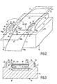
- One of the attachment parts 17 is shown greatly enlarged in FIGS. 2 and 3 together with the magnetic head and the magnetic tape.
- the attachment part 17 shown in FIGS. 2 and 3 represents only one half of the holder 16 and has a base body 18 from which projections 19, 20 project laterally.
- the base body 18 has a guide surface 21 which is cylindrically curved in the width direction according to arrow 22.
- the guide surface 21 is set back somewhat from the band contact surface 12 and its tangential plane. This ensures that the magnetic tape 11 between guide rollers, not shown, in the magnet tape cassette and the tape contact surface 12 has a curved course, both over the tape contact surface 12 and over the guide surface 21. This will tighten the band.
- the extension 19 has an alignment surface 23 adjacent to the guide surface 21.
- This alignment surface 23 is approximately perpendicular to the tangential surface to the guide surface 21.
- the alignment surface is arranged at one end of the guide surface 21, at the other end of the guide surface 21 there is a control edge 24 which, like the guide surface 21, is cylindrically curved.
- the tangential surface of the control edge includes an obtuse angle of 110 ° to 130 ° with the tangential surface of the guide surface 21. The angle is preferably approximately 120 °.
- the distance between the alignment surface 23 and the control edge 24 in the transition 21a to the guide surface 21 is smaller than the bandwidth. This means, as can be seen from FIG.
- Each control edge 24 of the lugs 20 merges at a distance from the guide surface 21 into an avoidance limiter surface 26 which has lateral edges 26a, 26b and between which the surface 26 preferably has a cylindrical curvature which in the center of the surface has the smallest distance to the opposite alignment surface 23.
- the distance c between the opposite alignment surface 23 and the avoidance limiter surface 26 is greater than the bandwidth b; the distance c remains the same from the transition point 27 to the open side. 2 and 3, the playing position of the tape is 11 and the cue position of the tape is 11 '. In the cue position 11 ', the magnetic tape is still in contact with the air gap 25 and the tape contact surface 12 in the area of the air gap, but it has been lifted from the guide surfaces 21.
- This cue position serves to reduce the friction of the tape when the tape is running fast, but to still take signals from the magnetic tape.
- the position of the magnetic tape 11 'in the cue position in the width direction 22 is limited with play between the alignment surface 23 and the evasive limiter surface 26th
- diverging capture surfaces 29 are provided in relation to the avoidance limiter surface 26, so that the magnate tape 11 can run into the holder 16 fastened to the head when the magnetic head 13 is advanced.
- An imaginary tangential surface to the avoidance limiter surface 26 runs approximately perpendicular to the band contact surface 12. This means that the alignment surface 23 and the avoidance limiter surface 26 in the direction of an arrow 30 according to FIG. H. the direction of head movement, locally have an approximately parallel course.
- the head holder with its individual parts is injection molded from plastic and is therefore easy and precise to close manufacture.
- the head holder can preferably be provided with a snap connection by means of which the head holder can be snapped onto the head plate with the head.
Landscapes
- Engineering & Computer Science (AREA)
- Manufacturing & Machinery (AREA)
- Adjustment Of The Magnetic Head Position Track Following On Tapes (AREA)
- Registering, Tensioning, Guiding Webs, And Rollers Therefor (AREA)
Abstract
Description
Die Erfindung bezieht sich auf ein Magnetbandkassettengerät mit einer Kopfplatte und einem auf der Kopfplatte angeordneten Magnetkopf mit zylindrischer Bandkontaktfläche und Luftspalt, wobei der Magnetkopf zu einer Kopfeinheit gehört, mit einer Kopfhalterung, die in Bandtransportrichtung je eine Bandführung vor und hinter dem Magnetkopf aufweist mit zylindrisch gekrümmten Führungsflächen sowie diese einseitig begrenzenden Ausrichtflächen an jeweils einem ihrer axialen Enden, wobei eine gedachte, die Ausrichtflächen verbindende Fläche senkrecht auf einer Ebene durch den Luftspalt steht, wobei an jeder der Führungsflächen an dem anderen axialen Ende ein Steuerrand anschließt, der aufgrund seiner Neigung zur Führungsfläche das Magnetband beim Bandtransport mit einer Bandkante gegen die jeweilige Ausrichtfläche gedrückt hält, und wobei die Axiallänge der Führungsfläche kleiner ist oder gleich der Bandbreite, und eine Magnetkopfeinheit für ein solches Magnetbandkassettengerät.The invention relates to a magnetic tape cassette device with a head plate and a magnetic head arranged on the head plate with a cylindrical tape contact surface and an air gap, the magnetic head belonging to a head unit, with a head holder which has a tape guide in the tape transport direction in front and behind the magnetic head with cylindrically curved ones Guide surfaces and these unilaterally delimiting alignment surfaces at one of their axial ends, an imaginary surface connecting the alignment surfaces being perpendicular to the plane through the air gap, with a control edge adjoining each of the guide surfaces at the other axial end, which due to its inclination to the guide surface holds the magnetic tape during tape transport with a tape edge against the respective alignment surface, and the axial length of the guide surface is less than or equal to the tape width, and a magnetic head unit for such a magnetic tape cassette device.
Ein derartiges Magnetbandkassettengerät mit eine Kopfeinheit und einer zur Kopfeinheit gehörenden Halterung ist aus der EP-PS 0 120 518 (PHN 10.602) bekannt. Der Vorteil der Kopfhalterung bei diesem Magnetbandkassetten gerät besteht darin, daß das Magnetband während seines Transportes über die Bandkontaktfläche des Magnetkopfes immer in der richtigen Azimutlage liegt. Dies ist wichtig bei der Verwendung von vorbespielten Bändern, die auf anderen Geräten vorbespielt wurden. Die Azimutlage des Magnetbandkassettengerätes muß für eine gute Wiedergabe der Azimutlage des Aufnahmegerätes entsprechen. Außerdem kann der Magnetkopf zusammen mit der Halterung bereits beim Hersteller als komplette Einheit angefertigt werden. Bei dem Gerätehersteller sind dann keine Azimuteinstellungen mehr erforderlich.Such a magnetic tape cassette device with a head unit and a holder belonging to the head unit is known from EP-PS 0 120 518 (PHN 10.602). The advantage of the head holder with this magnetic tape cassette device is that the magnetic tape is always in the correct azimuth position during its transport over the tape contact surface of the magnetic head. This is important when using pre-recorded tapes that have been pre-recorded on other devices. The azimuth position of the magnetic tape cassette device must correspond to the azimuth position of the recording device for good reproduction. In addition, the magnetic head can be manufactured together with the holder as a complete unit at the manufacturer. The device manufacturer then no longer requires azimuth settings.
Bei dieser Bandführung läuft das Band im Spielbetrieb von einer Bandführungsfläche unmittelbar vor dem Magnetkopf über die Bandkontaktfläche des Magnetkopfes zur unmittelbar hinter dem Kopf befindlichen Bandführungsfläche. Dieser Bandverlauf ist leicht gekrümmt und gestrafft. Dies macht das Band steif, so daß die Steuerränder ihre Steuerfunktion ausüben können, indem sie das Magnetband in einer Richtung gegen die Ausrichtflächen drücken. In dem Cue- oder MSS-(Music Sensing System)-Betrieb, der dem Pausensuchen dient, ist der Tonkopf zurückgezogen. Der Andruck des Bandes an die Ausrichtflächen geht verloren.With this tape guide, the tape runs in play mode from a tape guide surface immediately in front of the magnetic head over the tape contact surface of the magnetic head to the tape guide surface immediately behind the head. This band course is slightly curved and tightened. This makes the tape stiff so that the control edges can perform their control function by pushing the magnetic tape against the alignment surfaces in one direction. In the cue or MSS (Music Sensing System) mode, which is used to search for a break, the sound head is retracted. The pressure of the tape on the alignment surfaces is lost.
Aus der US-PS 46 46 186 ist es bekannt, für Spielbetrieb ein der Bandführung dienendes Gabelpaar, bei dem der Zinkenabstand etwa der Bandbreite entspricht, in der Nähe des Tonkopfes und eine für Cue-Betrieb gedachte Bandführungsgabel mit größerem Zinkenabstand weit ab vom Tonkopf einzusetzen. Beim Zurückziehen des Tonkopfes ist nur noch die weit abliegende Bandführungsgabel wirksam. Das Ban verliert seine Führung am Tonkopf Bei höheren Bandgeschwindigkeiten kann dies zie Schwingungen führen, die das Auslesen der Signale aus der Tonspur beeinträchtigen oder sogar zu Beschädigungen der Bandränder führen können.From US-PS 46 46 186 it is known for play operation a pair of forks serving the tape guide, in which the tine spacing corresponds approximately to the bandwidth, near the head and a tape guide fork intended for cue operation with a larger tine spacing far from Insert the head. When the tape head is pulled back, only the far-away tape guide fork is effective. The ban loses its leadership on the tape head. At higher tape speeds, this can lead to vibrations that impair the reading of the signals from the audio track or even damage the tape edges.
Es ist Aufgabe der Erfindung, ein Magnetbandkassettengerät und eine Magnetkopfeinheit für ein derartiges Magnetbandkassettengerät der eingangs erwähnten Art derart zu verbessern, daß das Magnetband auch in der Cue-Lage eine Art von Führung vorfindet.It is an object of the invention to improve a magnetic tape cassette device and a magnetic head unit for such a magnetic tape cassette device of the type mentioned at the outset such that the magnetic tape also has a type of guide in the cue position.
Die gestellte Aufgabe ist erfindungsgemäß dadaurch gelöst, daß jeder Steuerrand der Kopfhalterung in einem Abstand von der Führungsfläche in eine Ausweichbegrenzerfläche übergeht, wobei von der Übergangsstelle an der Abstand zwischen den gegenüberliegenden Ausrichtflächen und Ausweichbegrenzerflächen derart größer als die Bandbreite ist, daß beim Abheben des Magnetbandes von den Führungsflächen bei noch bleibendem Berühren des Magnetbandes mit der Bandkontaktfläche des Kopfes die Lage des Magnetbandes in dessen Breitenrichtung mit Spiel begrenzt ist, und wobei der genannte Abstand von der Mitte der jeweiligen Ausweichbegrenzerfläche zu deren seitlichen Rändern hin zunimmt.The object is achieved according to the invention in that each control edge of the head holder merges at a distance from the guide surface into an alternate limiter surface, the distance between the opposite alignment surfaces and alternate limiter surfaces being so greater than the bandwidth that the magnetic tape is lifted off when it is lifted off the guide surfaces while the magnetic tape is still in contact with the tape contact surface of the head, the position of the magnetic tape is limited in the width direction thereof with play, and the said distance increases from the center of the respective escape limiter surface to its lateral edges.
Durch die Einführung von Ausweichbegrenzerflächen ist die Funktion der Steuerränder während des normalen Aufnahme- oder Spielbetriebes nicht beeinträchtigt. Die Ausweichbegrenzerflächen sorgen aber in der Cue-Lage dafür, daß das Magnetband nur in gewissen kleinen Grenzen in der Breitenrichtung seitlich ausweichen kann. Um sicher zu sein, daß diese begrenzte Führung immer richtig arbeitet, ist vorgesehen, daß der gegenseitige Abstand zwischen Ausweichbegrenzerflächen und Ausrichtflächen immer größer ist als die größte Bandbreite. Die Ausweichflächen sind ebenso wie alle übrigen Flächen der Halterung einstückig mit der Halterung zu fertigen. Da die das Band beeinflussenden Flächen in Bandlaufrichtung vor und hinter dem Kopf liegen, wird der Andruckfilz der Kassette in seiner Position und Funktion von der Halterung nicht gestört.The introduction of alternative limiter areas means that Function of the control margins is not impaired during normal recording or game operations. In the cue position, however, the escape limiter surfaces ensure that the magnetic tape can only move sideways in the width direction within certain small limits. In order to be sure that this limited guidance always works correctly, it is provided that the mutual distance between the alternative limiter surfaces and the alignment surfaces is always greater than the greatest bandwidth. The evasive surfaces, like all other surfaces of the holder, are to be manufactured in one piece with the holder. Since the surfaces influencing the tape are in front of and behind the head in the tape running direction, the position and function of the pressure felt of the cassette is not disturbed by the holder.
Nach einer weiteren Ausgestaltung dere Erfindung ist vorgesehen, daß die Ausweichbegrenzerflächen zylindrisch gekrümmt sind. Aufgrund der zylindrischen Krümmung haben die Bandränder mit den Ausweichbegrenzerflächen immer nur einen punktförmigen, praktisch niemals flächigen Kontakt. Dies ist wichtig bei veränderter Höhenlage des Bandlaufes vor und hinter der Magnetkopfeinheit. Dies kann seine Ursache in Lauffehlern innerhalb der Kassette haben.According to a further embodiment of the invention it is provided that the escape limiter surfaces are cylindrically curved. Due to the cylindrical curvature, the band edges always have only point-like, practically never flat contact with the escape limiter surfaces. This is important if the height of the tape run changes in front of and behind the magnetic head unit. This can be caused by running errors within the cassette.
Nach einer weiteren Ausgestaltung der Erfindung ist vorgesehen, daß eine Tangentialfläche zur Ausweichbegrenzerfläche etwa senkrecht zur Bandkontaktfläche verläuft. Damit verläuft die Ausweichbegrenzerfläche etwa parallel zur Ausrichtfläche und ist sichergestellt, daß das Magnetband, auch wenn es sich quer zur Transportrichtung auf der Bandkontaktfläche verschiebt, weiterhin grob geführt ist.According to a further embodiment of the invention it is provided that a tangential surface to the avoidance limiter surface runs approximately perpendicular to the band contact surface. The escape limiter surface thus runs approximately parallel to the alignment surface and it is ensured that the magnetic tape, even if it is displaced transversely to the transport direction on the tape contact surface, is still roughly guided.
Nach einer weiteren Ausgestaltung der Erfindung ist vorgesehen, daß an die freien Enden der Ausweichbegrenzerflächen gegenüber den Ausrichtflächen divergierende Einfangflächen vorgesehen sind. Beim Vorschieben der Magnetkopfeinheit gegenüber der Magnetbandkassette wird das Magnetband dann immer von der Halterung eingefangen.According to a further embodiment of the invention it is provided that diverging capture surfaces are provided on the free ends of the escape limiter surfaces relative to the alignment surfaces. When the magnetic head unit is advanced over the magnetic tape cassette, the magnetic tape is then always caught by the holder.
Die Erfindung wird anhand der Zeichnung näher erläutert. Es zeigen:
- Fig. 1 ein Magentbandkassettengerät mit einer Magnetkopfeinheit und einer Kopfhalterung zur Azimutführung eines Magnetbandes,
- Fig. 2 eine schaubildliche Darstellung eines Magnetkopfteiles und eines Teiles einer Magnetkopfhalterung, die an einer nicht dargestellten Kopfplatte eines Magnetbandkassettengerätes angeordnet ist,
- Fig. 3 einen Schnitt längs der Linie II-II nach Fig. 1 zur Darstellung von zwei verschiedenen Lagen des Magnetbandes gegenüber den Bandführungsflächen der Halterung.
- 1 shows a magnetic tape cassette device with a magnetic head unit and a head holder for azimuth guidance of a magnetic tape,
- 2 shows a diagrammatic representation of a magnetic head part and a part of a magnetic head holder which is arranged on a head plate (not shown) of a magnetic tape cassette device,
- Fig. 3 shows a section along the line II-II of FIG. 1 to show two different layers of the magnetic tape relative to the tape guide surfaces of the holder.
Fig. 1 zeigt ein Magentbandkassettengerät mit einem Gehäuse 1, einem Antriebsmotor 2 und einer Kassettenhaltevorrichtung 3. Zur Betätigung der verschiedenen Betriebsfunktionen des Magnetbandkassettengerätes 1 dienen drei Tasten 4, 5, 6, die innerhalb des Gerätes auf nicht dargestellte Weise geführt sind. In die Kassettenhalterung 3 ist eine Magnetbandkassette 7 eingeschoben, die einen an einer Feder 8 abgestützten Andruckfilz 9 aufweist.Fig. 1 shows a magnetic tape cassette device with a housing 1, a
Das Magnetbandkassettengerät hat eine Kopfplatte 10, die in Richtung auf die Magnetbandkassette 7 vor und zurück fahrbar ist. Zwischen einer voll vorgefahrenen Spielstellung und einer ganz zurückgefahrenen Stellung gibt es noch eine Cue-Stellung. In der Zeichnung ist die Spielstellung dargestellt. In Fig. 1 ist zu erkennen, daß der Andruckfilz 9 ein Magnetband 11 gegen eine Bandkontaktfläche 12 eines Magnetkopfes 13 drückt.The magnetic tape cassette device has a
Zum Bandtransport dient eine Tonwelle 14, gegen die eine Andruckrolle 15 drückt. Zwischen der Andruckrolle und der Tonwelle wird das Magnetband 11 geführt und transportiert. Der Magnetkopf 13 ist auf der Kopfplatte 10 angeordnet mittels einer Halterung 16. Die Halterung 16 und der Magnetkopf 13 sind fabrikmäßig zu einer Einheit verbunden.A
Die Halterung 16 hat seitlich des Magnetkopfes Ansatzteile 17, zwischen denen das Magnetband 11 hinduch läuft. Eines der Ansatzteile 17 ist in Fig. 2 und 3 stark vergrößert dargestellt zusammen mit dem Magnetkopf und dem Magnetband.The
Das in Fig. 2 und 3 dargestellte Ansatzteil 17 stellt nur die eine Hälfte der Halterung 16 dar und hat einen Grundkörper 18, von dem seitlich Ansätze 19, 20 aufragen. Der Grundkörper 18 weist eine Führungsfläche 21 auf, die in Breitenrichtung gemäß Pfeil 22 zylindrisch gekrümmt ist. Die Führungsfläche 21 ist gegenüber der Bandkontaktfläche 12 und deren Tangentialebene etwas zurückgesetzt. Hierdurch ist sichergestellt, daß das Magnetband 11 zwischen nicht darstellten Führungsrollen in der Magnet bandkassette und der Bandkontaktfläche 12 einen gekrümmten Verlauf hat, und zwar sowohl über die Bandkontaktfläche 12 hinweg als auch über die Führungsfläche 21 hinweg. Damit wird das Band gestrafft.The
Der Ansatz 19 weist angrenzend an die Führungsfläche 21 eine Ausrichtfläche 23 auf. Diese Ausrichtfläche 23 steht etwa senkrecht auf der Tangentialfläche zur Führungsfläche 21. Während die Ausrichtfläche an dem einen Ende der Führungsfläche 21 angeordnet ist, befindet sich am anderen Ende der Führungsfläche 21 ein Steuerrand 24, der wie die Führungsfläche 21 zylindrisch gekrümmt ist. Die Tangentialfläche des Steuerrandes schließt mit der Tangentialfläche der Führungsfläche 21 einen stumpfen Winkel von 110° bis 130° ein. Vorzugsweise beträgt der Winkel etwa 120°. Der Abstand zwischen der Ausrichtfläche 23 und dem Steuerrand 24 im Übergang 21a zu der Führungsfläche 21 ist kleiner als die Bandbreite. Das bedeutet, wie aus Fig. 3 zu ersehen ist, daß das Magnetband 11 mit einem Rand 11a immer ein wenig auf dem Steuerrand 24 aufliegt und an der Ausrichtfläche 23 anliegt. Auf diese Weise wird die Azimutlage des Magnetbandes gegenüber dem Luftspalt 25 genau eingestellt. Nähere Einzelheiten über die Funktionsweise dieser Einstellung sind aus der EP-PS 0 120 518 (PHN 10.602) bekannt. Es wird deshalb zur näheren Erläuterung auf diese Druckschrift verwiesen.The
Jeder Steuerrand 24 der Ansätze 20 geht in einem Abstand von der Führungsfläche 21 in eine Ausweichbegrenzerfläche 26 über, die seitliche Ränder 26a, 26b aufweist und zwischen denen die Fläche 26 vorzugsweise eine zylindrische Krümmung aufweist, die in der Flächenmitte den kleinsten Abstand zu der gegenüberliegenden Ausrichtfläche 23 aufweist. An der Übergangsstelle 27 ist der Abstand c zwischen der gegenüberliegenden Ausrichtfläche 23 und der Ausweichbegrenzerfläche 26 größer als die Bandbreite b; der Abstand c bleibt von der Übergangsstelle 27 an zur offenen Seite hin gleich. In Fig. 2 und 3 ist die Spiellage des Bandes mit 11 und die Cue-Lage des Bandes mit 11′ bezeichnet. In der Cue-Lage 11′ hat das Magnetband zwar noch Kontakt mit dem Luftspalt 25 und der Bandkontaktfläche 12 im Gebiet des Luftspaltes, von den Führungsflächen 21 hat es sich jedoch abgehoben. Diese Cue-Lage dient dazu, bei schnellem Bandlauf die Reibung des Bandes zu verringern, jedoch noch Signale von dem Magnetband abzunehmen. Wie aus Fig. 3 zu ersehen ist, ist die Lage des Magnetbandes 11′ in der Cue-Lage in dessen Breitenrichtung 22 mit Spiel begrenzt zwischen der Ausrichtfläche 23 und der Ausweichbegrenzerfläche 26.Each
An dem freien Ende 28 der Ausweichbegrenzerfläche 26 sind gegenüber der Ausweichbegrenzerfläche 26 divergierende Einfangflächen 29 vorgesehen, damit das Magnatband 11 beim Vorfahren des Magnetkopfes 13 in die am Kopf befestigte Halterung 16 einlaufen kann. Eine gedachte Tangentialfläche zur Ausweichbegrenzerfläche 26 verläuft etwa senkrecht zur Bandkontaktfläche 12. Dies bedeutet, daß die Ausrichtfläche 23 und die Ausweichbegrenzerfläche 26 in Richtung eines Pfeiles 30 nach Fig. 1, d. h. der Kopfbewegungsrichtung, örtlich einen etwa parallelen Verlauf haben.At the
Die Kopfhalterung mit ihren Einzelteilen ist aus Kunststoff gespritzt und ist dadurch einfach und genau zu fertigen. Vorzugsweise kann die Kopfhalterung gleich mit einer Schnappverbindung versehen sein, mittels der die Kopfhalterung mit Kopf auf die Kopfplatte aufschnappbar ist.The head holder with its individual parts is injection molded from plastic and is therefore easy and precise to close manufacture. The head holder can preferably be provided with a snap connection by means of which the head holder can be snapped onto the head plate with the head.
Claims (5)
Priority Applications (1)
| Application Number | Priority Date | Filing Date | Title |
|---|---|---|---|
| DE8916097U DE8916097U1 (en) | 1988-04-14 | 1989-04-10 | Magnetic tape cassette device with a head plate and a magnetic head unit for this magnetic tape cassette device |
Applications Claiming Priority (2)
| Application Number | Priority Date | Filing Date | Title |
|---|---|---|---|
| DE3812362A DE3812362A1 (en) | 1988-04-14 | 1988-04-14 | MAGNETIC TAPE CASSETTE DEVICE WITH A HEAD PLATE AND A MAGNETIC HEAD UNIT FOR THIS MAGNETIC TAPE CASSETTE DEVICE |
| DE3812362 | 1988-04-14 |
Publications (2)
| Publication Number | Publication Date |
|---|---|
| EP0337566A2 true EP0337566A2 (en) | 1989-10-18 |
| EP0337566A3 EP0337566A3 (en) | 1990-09-26 |
Family
ID=6351934
Family Applications (1)
| Application Number | Title | Priority Date | Filing Date |
|---|---|---|---|
| EP19890200888 Withdrawn EP0337566A3 (en) | 1988-04-14 | 1989-04-10 | Magnetic tape cassette apparatus with a head plate and magnetic head unit for this apparatus |
Country Status (5)
| Country | Link |
|---|---|
| US (1) | US4962438A (en) |
| EP (1) | EP0337566A3 (en) |
| JP (1) | JPH01162143U (en) |
| CN (1) | CN2051007U (en) |
| DE (1) | DE3812362A1 (en) |
Cited By (4)
| Publication number | Priority date | Publication date | Assignee | Title |
|---|---|---|---|---|
| EP0385359A2 (en) * | 1989-02-28 | 1990-09-05 | Canon Denshi Kabushiki Kaisha | Magnetic head |
| EP0532012A2 (en) * | 1991-09-11 | 1993-03-17 | Matsushita Electric Industrial Co., Ltd. | Magnetic head assembly |
| EP0549020A2 (en) * | 1991-12-11 | 1993-06-30 | Koninklijke Philips Electronics N.V. | Apparatus suitable for cooperation with a cassette provided with magnetic tape, magnetic-head unit and magnetic-head for use in the apparatus, housing suitable for use in the magnetic-head unit, and method of manufacturing the magnetic-head unit |
| EP0786764A1 (en) * | 1996-01-26 | 1997-07-30 | Philips Patentverwaltung GmbH | Magnetic tape cassette apparatus |
Families Citing this family (10)
| Publication number | Priority date | Publication date | Assignee | Title |
|---|---|---|---|---|
| US5134536A (en) * | 1988-08-18 | 1992-07-28 | Kabushiki Kaisha Sankyo Seiki Seisakusho | Tape guide for magnetic head |
| JPH04216354A (en) * | 1990-02-16 | 1992-08-06 | Pioneer Electron Corp | Magnetic head device |
| US5253135A (en) * | 1990-03-13 | 1993-10-12 | Canon Denshi Kabushiki Kaisha | Magnetic head having a tape sliding surface and projections formed on the tape sliding surface |
| CN1058349C (en) * | 1992-06-10 | 2000-11-08 | 阿鲁普斯电气株式会社 | Magnetic head |
| US5546259A (en) * | 1992-11-25 | 1996-08-13 | Matsushita Electric Industrial Co., Ltd. | Tape transporting apparatus including a tape guide with variable restricting force regions, each used depending upon the amount of tape tension |
| JP2587047Y2 (en) * | 1993-05-26 | 1998-12-14 | アルプス電気株式会社 | Magnetic head device |
| JPH0823979B2 (en) * | 1993-08-23 | 1996-03-06 | インターナショナル・ビジネス・マシーンズ・コーポレイション | Tape guide |
| CN1137835A (en) * | 1994-09-16 | 1996-12-11 | 菲利浦电子有限公司 | System for information storage and/or reproduction and caseette for information storage and/or reproduction |
| DE19519371A1 (en) * | 1995-05-26 | 1996-11-28 | Philips Patentverwaltung | Magnetic head with a tape guide |
| US20050133660A1 (en) * | 2003-12-23 | 2005-06-23 | Anderson James C. | Method and apparatus for guiding a moving tape |
Citations (7)
| Publication number | Priority date | Publication date | Assignee | Title |
|---|---|---|---|---|
| DE2460403B1 (en) * | 1974-12-20 | 1976-08-12 | Licentia Gmbh | BELT GUIDE DEVICE |
| GB2087631A (en) * | 1980-11-18 | 1982-05-26 | Sony Corp | Methods and apparatus for recording and reproducing information signals |
| EP0063398A1 (en) * | 1981-04-13 | 1982-10-27 | Koninklijke Philips Electronics N.V. | Magnetic-tape cassette apparatus and magnetic-head unit for use in conjunction with such apparatus |
| US4455002A (en) * | 1981-08-13 | 1984-06-19 | Olympus Optical Co., Ltd. | Tape guide device of a magnetic tape driving apparatus |
| EP0120518A1 (en) * | 1983-02-28 | 1984-10-03 | Koninklijke Philips Electronics N.V. | Magnetic-tape-cassette apparatus and magnetic-head unit for use in such apparatus |
| JPS61187150A (en) * | 1985-02-15 | 1986-08-20 | Akai Electric Co Ltd | Reverse type tape running device |
| US4646186A (en) * | 1982-09-14 | 1987-02-24 | Alps Electric Co., Ltd. | Cassette tape recorder with plural tape guide structure |
Family Cites Families (2)
| Publication number | Priority date | Publication date | Assignee | Title |
|---|---|---|---|---|
| JPS5839556Y2 (en) * | 1979-01-18 | 1983-09-06 | ナカミチ株式会社 | pad abutting device |
| US4894737A (en) * | 1986-12-05 | 1990-01-16 | Canon Kabushiki Kaisha | Magnetic head apparatus having projections extending from at least a front side thereof |
-
1988
- 1988-04-14 DE DE3812362A patent/DE3812362A1/en not_active Ceased
-
1989
- 1989-04-10 EP EP19890200888 patent/EP0337566A3/en not_active Withdrawn
- 1989-04-11 CN CN89204454U patent/CN2051007U/en not_active Expired - Lifetime
- 1989-04-11 US US07/336,193 patent/US4962438A/en not_active Expired - Fee Related
- 1989-04-11 JP JP1989041724U patent/JPH01162143U/ja active Pending
Patent Citations (7)
| Publication number | Priority date | Publication date | Assignee | Title |
|---|---|---|---|---|
| DE2460403B1 (en) * | 1974-12-20 | 1976-08-12 | Licentia Gmbh | BELT GUIDE DEVICE |
| GB2087631A (en) * | 1980-11-18 | 1982-05-26 | Sony Corp | Methods and apparatus for recording and reproducing information signals |
| EP0063398A1 (en) * | 1981-04-13 | 1982-10-27 | Koninklijke Philips Electronics N.V. | Magnetic-tape cassette apparatus and magnetic-head unit for use in conjunction with such apparatus |
| US4455002A (en) * | 1981-08-13 | 1984-06-19 | Olympus Optical Co., Ltd. | Tape guide device of a magnetic tape driving apparatus |
| US4646186A (en) * | 1982-09-14 | 1987-02-24 | Alps Electric Co., Ltd. | Cassette tape recorder with plural tape guide structure |
| EP0120518A1 (en) * | 1983-02-28 | 1984-10-03 | Koninklijke Philips Electronics N.V. | Magnetic-tape-cassette apparatus and magnetic-head unit for use in such apparatus |
| JPS61187150A (en) * | 1985-02-15 | 1986-08-20 | Akai Electric Co Ltd | Reverse type tape running device |
Non-Patent Citations (1)
| Title |
|---|
| PATENT ABSTRACTS OF JAPAN vol. 11, no. 12 (P-535)(2459) 13 Januar 1987, & JP-A-61 187150 (AKAI ELECTRIC CO LTD) 20 August 1986, * |
Cited By (10)
| Publication number | Priority date | Publication date | Assignee | Title |
|---|---|---|---|---|
| EP0385359A2 (en) * | 1989-02-28 | 1990-09-05 | Canon Denshi Kabushiki Kaisha | Magnetic head |
| EP0385359A3 (en) * | 1989-02-28 | 1992-04-15 | Canon Denshi Kabushiki Kaisha | Magnetic head |
| US5574606A (en) * | 1989-02-28 | 1996-11-12 | Canon Denshi Kabushiki Kaisha | Magnetic head having dust handling tape slide surface |
| EP0532012A2 (en) * | 1991-09-11 | 1993-03-17 | Matsushita Electric Industrial Co., Ltd. | Magnetic head assembly |
| EP0532012A3 (en) * | 1991-09-11 | 1994-08-10 | Matsushita Electric Ind Co Ltd | Magnetic head assembly |
| US5638238A (en) * | 1991-09-11 | 1997-06-10 | Matsushita Electric Industrial Co., Ltd. | Magnetic head device with magnetic tape guides |
| EP0769779A3 (en) * | 1991-09-11 | 1998-04-22 | Matsushita Electric Industrial Co., Ltd. | Magnetic head assembly |
| EP0549020A2 (en) * | 1991-12-11 | 1993-06-30 | Koninklijke Philips Electronics N.V. | Apparatus suitable for cooperation with a cassette provided with magnetic tape, magnetic-head unit and magnetic-head for use in the apparatus, housing suitable for use in the magnetic-head unit, and method of manufacturing the magnetic-head unit |
| EP0549020A3 (en) * | 1991-12-11 | 1993-12-22 | Koninkl Philips Electronics Nv | Apparatus suitable for cooperation with a cassette provided with magnetic tape, magnetic-head unit and magnetic-head for use in the apparatus, housing suitable for use in the magnetic-head unit, and method of manufacturing the magnetic-head unit |
| EP0786764A1 (en) * | 1996-01-26 | 1997-07-30 | Philips Patentverwaltung GmbH | Magnetic tape cassette apparatus |
Also Published As
| Publication number | Publication date |
|---|---|
| US4962438A (en) | 1990-10-09 |
| DE3812362A1 (en) | 1989-10-26 |
| EP0337566A3 (en) | 1990-09-26 |
| CN2051007U (en) | 1990-01-10 |
| JPH01162143U (en) | 1989-11-10 |
Similar Documents
| Publication | Publication Date | Title |
|---|---|---|
| EP0337566A2 (en) | Magnetic tape cassette apparatus with a head plate and magnetic head unit for this apparatus | |
| DE2825457C2 (en) | Tape cartridge | |
| DE2323118A1 (en) | TAPE CASSETTE | |
| DE3017201C2 (en) | Magnetic head for a tape device | |
| DE2946419A1 (en) | CASSETTE RECORDER | |
| DE2730381A1 (en) | TAPE CASSETTE | |
| DE3003952A1 (en) | DEVICE FOR RECORDING AND / OR PLAYING BACK SIGNALS ON A MAGNETIC TAPE | |
| EP0115275B1 (en) | Video recorder drive | |
| DE2318641C3 (en) | Cassette tape recorder | |
| DE2941437C2 (en) | Cassette tape recorder with automatic rewind | |
| EP0088472B1 (en) | Magnetic-tape cassette | |
| DE2164317C3 (en) | Device for the automatic adjustment of a magnetic head of a magnetic tape recorder to the information track to be read | |
| EP0667612A2 (en) | Device for the reverse play drive of a magnetic tape drive apparatus | |
| DE2538935C3 (en) | Adjustment device for the headset and the erase head on a head support plate in a cassette tape recorder | |
| DE3213621A1 (en) | TAPE CASSETTE AND TAPE RECORDER | |
| AT395488B (en) | DEVICE FOR RECORDING AND PLAYING BACK SIGNALS WITH AT LEAST ONE ROTATING MAGNETIC HEAD | |
| DE1128165B (en) | Cassette magnetic recorder with tape-shaped recording medium | |
| DE2424621A1 (en) | TAPE RECORDER | |
| DE2100591B2 (en) | Recording ^ and / or playback device | |
| DE2928849A1 (en) | MAGNETIC CARD RECORDING AND / OR PLAYBACK DEVICE | |
| EP0632447B1 (en) | Device for controlling a mechanical tension for a tape in a cassette | |
| DE2329693A1 (en) | ELECTROMAGNETIC CONVERTER WITH EXTINGUISHER ASSEMBLY | |
| DE4405302A1 (en) | Magnetic tape device | |
| DE2334672C2 (en) | Tape guide device in an endless magnetic tape cassette | |
| DE1222700B (en) | Tape recorder with shut-off device by pulling the expired magnetic tape |
Legal Events
| Date | Code | Title | Description |
|---|---|---|---|
| PUAI | Public reference made under article 153(3) epc to a published international application that has entered the european phase |
Free format text: ORIGINAL CODE: 0009012 |
|
| AK | Designated contracting states |
Kind code of ref document: A2 Designated state(s): DE FR GB IT |
|
| PUAL | Search report despatched |
Free format text: ORIGINAL CODE: 0009013 |
|
| AK | Designated contracting states |
Kind code of ref document: A3 Designated state(s): DE FR GB IT |
|
| 17P | Request for examination filed |
Effective date: 19910321 |
|
| 17Q | First examination report despatched |
Effective date: 19920825 |
|
| STAA | Information on the status of an ep patent application or granted ep patent |
Free format text: STATUS: THE APPLICATION HAS BEEN WITHDRAWN |
|
| 18W | Application withdrawn |
Withdrawal date: 19930618 |