EP0336476A1 - Inspection device - Google Patents
Inspection device Download PDFInfo
- Publication number
- EP0336476A1 EP0336476A1 EP89200741A EP89200741A EP0336476A1 EP 0336476 A1 EP0336476 A1 EP 0336476A1 EP 89200741 A EP89200741 A EP 89200741A EP 89200741 A EP89200741 A EP 89200741A EP 0336476 A1 EP0336476 A1 EP 0336476A1
- Authority
- EP
- European Patent Office
- Prior art keywords
- light
- light source
- optical
- block
- height
- Prior art date
- Legal status (The legal status is an assumption and is not a legal conclusion. Google has not performed a legal analysis and makes no representation as to the accuracy of the status listed.)
- Withdrawn
Links
Images
Classifications
-
- G—PHYSICS
- G01—MEASURING; TESTING
- G01N—INVESTIGATING OR ANALYSING MATERIALS BY DETERMINING THEIR CHEMICAL OR PHYSICAL PROPERTIES
- G01N21/00—Investigating or analysing materials by the use of optical means, i.e. using sub-millimetre waves, infrared, visible or ultraviolet light
- G01N21/84—Systems specially adapted for particular applications
- G01N21/88—Investigating the presence of flaws or contamination
- G01N21/90—Investigating the presence of flaws or contamination in a container or its contents
- G01N21/9054—Inspection of sealing surface and container finish
-
- G—PHYSICS
- G01—MEASURING; TESTING
- G01N—INVESTIGATING OR ANALYSING MATERIALS BY DETERMINING THEIR CHEMICAL OR PHYSICAL PROPERTIES
- G01N21/00—Investigating or analysing materials by the use of optical means, i.e. using sub-millimetre waves, infrared, visible or ultraviolet light
- G01N21/84—Systems specially adapted for particular applications
- G01N21/88—Investigating the presence of flaws or contamination
- G01N21/8851—Scan or image signal processing specially adapted therefor, e.g. for scan signal adjustment, for detecting different kinds of defects, for compensating for structures, markings, edges
- G01N2021/8887—Scan or image signal processing specially adapted therefor, e.g. for scan signal adjustment, for detecting different kinds of defects, for compensating for structures, markings, edges based on image processing techniques
-
- G—PHYSICS
- G01—MEASURING; TESTING
- G01N—INVESTIGATING OR ANALYSING MATERIALS BY DETERMINING THEIR CHEMICAL OR PHYSICAL PROPERTIES
- G01N2201/00—Features of devices classified in G01N21/00
- G01N2201/10—Scanning
- G01N2201/102—Video camera
Definitions
- the invention relates to a device for inspecting the upper surfaces of successive objects, for instance the mouth edges of glass bottles carried by a conveyor belt and guided thereby past the device, which device is provided with an optical system, comprising: a lighting system with a light source for lighting an upper surface of each object, and an optical imaging system for forming in each case an image of an upper surface.
- Such a device is known in diverse embodiments.
- the articles for inspection for example glass bottles, may, as a result of the nature of the production process, have mutual height differences. These height differences can cause problems with respect to the automatic visual inspection of the bottle mouth.
- a bottle inspection device is known for instance in which the height difference is levelled out by grasping each bottle under the flanged edge or neck that protrudes sideways at the top. Small differences in height can be evened out in this way.
- the invention has for its object to embody a device of the type described such that the above stated problem is solved.
- the invention also aims to embody a device of the said type such that it can be added to an existing conveyor device, for instance a bottle conveyor.
- a further object of the invention is to provide a device which enables a very compact construction.
- the invention aims to embody an inspection device such that great flexibility is achieved, and such that it always operates reliably irrespective of the mutual interval between the objects.
- the invention provides a device of the above described type that is characterized by: measuring means for measuring the height of one edge at a time, and adjustment means for setting the optical system on the basis of the height of an edge as determined by the measuring means.
- a very simple embodiment is one in which the adjustment means comprise an optical element displaceable along the optical axis.
- Such an optical element can be given a lighter form than a light source and is moreover a passive element so that difficulties with cables are not encountered.
- the optical element comprises a lens.
- a ring-shaped light source In order to obtain an intensive lighting for the inspection of bottle mouths or other annular reflecting sur severelyfaces, use is preferably made of a ring-shaped light source.
- a light source is per se known, for instance in the form of annularly arranged outer ends of light conductors coupled to a light source.
- the invention provides a device displaying the feature that the optical element comprises a transparent block, which block is cylinder-shaped, has an entry surface facing the light source, comprises a conical hollow, the top of which is directed to the entry surface, and has an exit surface extending in the form of a ring between the base of the hollow and the cylinder surface.
- the block functions as light conductor, as a result of which the light falling in on the entry surface is generated with very high yield via the exit surface.
- an embodiment can be used in which the cylinder surface and/or the cone surface is provided with a mirror.
- the block can be embodied such that the exit surface is diffusely transparent, for example is matted or provided with an opal covering layer. Using such an embodiment the directional preference of the outgoing light, if any, is reduced to negligible proportions.
- an embodiment can serve in which a screen not allowing passage of light is situated in the base of the cone.
- the block can in this case be embodied such that a fastening member is fixed in position in the block through the top of the cone.
- the optical element comprise a lens.
- This lens may be an objective lens of a video camera for instance so that in accordance with the invention focussing of the camera takes place on the basis of the measured height of the surface for measuring.
- the variant is recommended in which the lighting system is arranged for emitting a light bundle concentrated on the surface for lighting.
- the device can in this case be characterized by a ring-shaped mirror adapted to the shape of the surface for illumination, which mirror concentrates light coming from the light source on the upper surface for illumination.
- the device can in this latter case display the feature that the ring-shaped mirror possesses the form of the surface of a frustum cone, the centre line of which coincides with the optical axis of the lighting system.
- the device has the feature that the measuring means comprise a row of photo-cells.
- This row of photo-cells can form part of a linear-array camera.
- the invention further relates to a transparent block, as specified in the foregoing.
- This block can serve as light conductor for the concentrating of light concentrated on the entry surface onto the ring-shaped exit surface.
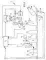
- Figure 1 shows an inspection device 1 disposed along a conveyor belt 2 which is driven by means that are not shown and which transports bottles 3 in the direction of an arrow 4.
- a light source with photo-cell 5 sends light to a reflector 6 and receives light reflected therefrom.
- a trigger signal is generated to a central processor unit or CPU 7.
- a light source 8 illuminates the thus detected bottle 3, as a result of which a linear array camera 9 arranged on the other side of this bottle 3 can feed a height signal to the CPU 7, this height signal being a measure for the height of the mouth 10 of bottle 3.
- the CPU 7 feeds this height signal to a servo-device 11 which supplies a servo-motor 12 with a corresponding energizing signal such that a spindle 13 is set into rotation. Coupled to this spindle is a lens unit 14 as well as a position recorder 15 which returns a position signal corresponding to the position of the lens unit 14 to the servo-device. A comparison of this position signal with the height signal by the servo-device 11 determines in a generally known manner the end position of lens unit 14.
- a light source 16 can light the bottle mouth 10 of a bottle 3 that has arrived at that location. Arrival of this bottle 3 is again detected by a light source/photo-cell 5 and the reflector 6. When the relevant light beam is broken this photo-cell passes on a trigger signal to the CPU 7, which then energizes the light source 16 in the form of a flash bulb in order to generate a flash.
- a video camera 20 observes the bottle mouth 10 via the semi-transparent mirror 17, forms an image thereof and transmits a video signal corresponding to that image to the CPU 7.
- a rejection signal may be generated in the CPU 7 and fed to a pusher member 21 which pushes a rejected bottle from the conveyor belt 2 when it is actuated.
- the CPU 7 further comprises decelerating means which must ensure that each bottle is identified unmistakably so that the setting of the lens unit 14 is used for the correct bottle 3 measured by the unit 5, 6, 8, 9. After passing the station 16, 14, 17, 18, 19, 20 a rejected bottle has to be removed by the pusher member 21 following a suitable deceleration subject to the speed of conveyor belt 2.
- a tachogenerator 22 measures the speed of the conveyor belt 2.
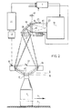
- FIG. 2 shows schematically a preferred embodiment.
- This diagram comprises a CPU 7 which is embodied in principle in the same manner as described briefly in figure 1. The description given there of height measurement will not be repeated here.
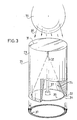
- the light source 16 in the form of flash bulb or stroboscope lamp sends its light to a light conductor in the form of a perspex block 23 (see the more detailed figure 3), which block is cylinder shaped and has an entry surface facing the light source 16, comprises a conical hollow 24, of which the top 32 is directed to the entry surface 31, and has a ring-shaped exit surface 33 extending between the base or bottom surface 34 of the conical hollow and the end of the cylinder surface 35 adjacent thereto.
- a screen 36 Located in the base 34 is a screen 36 not allowing the passage of light supported by a rod 37 which is screwed into position through the top 32 of the conical hollow 24 into the block 23.
- the light source 16 emits light to the entry surface 31 in the manner indicated by arrows 38. This light travels via block 23 and is generated via the matt exit surface 33, which can thus function as intensive, ring-shaped light source.
- This ring-shaped light source is indicated symbolically in figure 3 and designated with the reference numeral 39.
- the light originating from the source 39 is reflected by a mirror 25 which is disposed at 45°.
- a lens system 40 drawn here as a single lens, forms an image of the light source 39 such that via a ring-shaped mirror 28 with the form of the surface of a frustum cone it is imaged onto the mouth of a passing bottle 3 for inspection.
- the reflected light is directed onto the mouth 10 of the bottle 3 and the light reflected therefrom is fed via mirrors 29, 30 to the video camera 20.
- a mouth 10′ is of another bottle 3 and is situated at a greater height than the mouth 10 of the bottle 3.
- Drawn with broken lines is the beam path that the light transmitted by the source 39 now has to follow in order to be directed onto this mouth 10′.
- the positional alteration of the ring-shaped light source 39 necessary for this purpose is indicated with 41. This alteration of position is effected in a manner analogous to that described with reference to figure 1 by prior measurement of the height of mouth 10′ and the corresponding displacing of the perspex block 23 by means of a control mechanism that is embodied in a form wholly analogous to that of the units 11, 12, 13, 15 as in figure 1.
- the frustum conical mirror 28 can for example take the form of a vapour-deposited aluminium layer on a correspondingly shaped surface of a plate, for instance of perspex. Use can also be made of a metal block, for instance of aluminium, in which the mirror 28 is formed by a machining process.
Landscapes
- Physics & Mathematics (AREA)
- Health & Medical Sciences (AREA)
- Life Sciences & Earth Sciences (AREA)
- Chemical & Material Sciences (AREA)
- Analytical Chemistry (AREA)
- Biochemistry (AREA)
- General Health & Medical Sciences (AREA)
- General Physics & Mathematics (AREA)
- Immunology (AREA)
- Pathology (AREA)
- Length Measuring Devices By Optical Means (AREA)
- Investigating Materials By The Use Of Optical Means Adapted For Particular Applications (AREA)
Abstract
The invention relates to a device for inspecting the upper surfaces of successive objects, for instance the mouth (10) edges of glass bottles (3) carried by a conveyor belt (2) and guided thereby past the device, which device is provided with an optical system, comprising:
a lighting system with a light source (16) for lighting an upper surface of each object, and
an optical imaging system (20) for forming in each case an image of an upper surface. measuring means for measuring the height of one edge at a time, and
adjustment means for setting the optical system on the basis of the height of an edge as determined by the measuring means.
A very simple embodiment is one in which the adjustment means comprise an optical element displaceable along the optical axis. Such an optical element can be given a lighter form than a light source and is moreover a passive element so that difficulties with cables are not encountered.
Description
- The invention relates to a device for inspecting the upper surfaces of successive objects, for instance the mouth edges of glass bottles carried by a conveyor belt and guided thereby past the device, which device is provided with an optical system, comprising:
a lighting system with a light source for lighting an upper surface of each object, and
an optical imaging system for forming in each case an image of an upper surface. - Such a device is known in diverse embodiments. The articles for inspection, for example glass bottles, may, as a result of the nature of the production process, have mutual height differences. These height differences can cause problems with respect to the automatic visual inspection of the bottle mouth. A bottle inspection device is known for instance in which the height difference is levelled out by grasping each bottle under the flanged edge or neck that protrudes sideways at the top. Small differences in height can be evened out in this way.
- If the height differences are not or insufficiently evened out the optical path length from the light source to the image of the upper edge will not be the same for each bottle. As a result the setting of an inspection system cannot be carried out optimally. A consequence of this positional inaccuracy is that accuracy of inspection has to be sacrificed.
- The invention has for its object to embody a device of the type described such that the above stated problem is solved.
- The invention also aims to embody a device of the said type such that it can be added to an existing conveyor device, for instance a bottle conveyor.
- A further object of the invention is to provide a device which enables a very compact construction.
- Finally, the invention aims to embody an inspection device such that great flexibility is achieved, and such that it always operates reliably irrespective of the mutual interval between the objects.
- Generally, the invention provides a device of the above described type that is characterized by:
measuring means for measuring the height of one edge at a time, and
adjustment means for setting the optical system on the basis of the height of an edge as determined by the measuring means. - A very simple embodiment is one in which the adjustment means comprise an optical element displaceable along the optical axis. Such an optical element can be given a lighter form than a light source and is moreover a passive element so that difficulties with cables are not encountered.
- In a very simple embodiment the optical element comprises a lens.
- In order to obtain an intensive lighting for the inspection of bottle mouths or other annular reflecting surfaces, use is preferably made of a ring-shaped light source. Such a light source is per se known, for instance in the form of annularly arranged outer ends of light conductors coupled to a light source.
- Preference is given however within the scope of the invention to an embodiment of the lighting system that not only functions as ring-shaped light source but also emits as much directed light as possible to the annular surface for inspection, this in order to prevent masking of faults, which can occur in the case of radiation with non-directed light. In this respect the invention provides a device displaying the feature that the optical element comprises a transparent block, which block
is cylinder-shaped,
has an entry surface facing the light source,
comprises a conical hollow, the top of which is directed to the entry surface, and
has an exit surface extending in the form of a ring between the base of the hollow and the cylinder surface. In this embodiment the block functions as light conductor, as a result of which the light falling in on the entry surface is generated with very high yield via the exit surface. - In order to prevent undesired exit of light via the cylinder surface and/or the cone surface an embodiment can be used in which the cylinder surface and/or the cone surface is provided with a mirror.
- If desired the block can be embodied such that the exit surface is diffusely transparent, for example is matted or provided with an opal covering layer. Using such an embodiment the directional preference of the outgoing light, if any, is reduced to negligible proportions.
- In order to avoid spurious light possibly being generated via the cone surface an embodiment can serve in which a screen not allowing passage of light is situated in the base of the cone. The block can in this case be embodied such that a fastening member is fixed in position in the block through the top of the cone.
- In a very simple embodiment the optical element comprise a lens. This lens may be an objective lens of a video camera for instance so that in accordance with the invention focussing of the camera takes place on the basis of the measured height of the surface for measuring.
- In order to obtain the best possible image of the surface for inspection, the variant is recommended in which the lighting system is arranged for emitting a light bundle concentrated on the surface for lighting. In particular the device can in this case be characterized by a ring-shaped mirror adapted to the shape of the surface for illumination, which mirror concentrates light coming from the light source on the upper surface for illumination.
- For the inspection of an annular upper surface of objects, in particular the round mouths of bottles the device can in this latter case display the feature that the ring-shaped mirror possesses the form of the surface of a frustum cone, the centre line of which coincides with the optical axis of the lighting system.
- In a practical embodiment the device has the feature that the measuring means comprise a row of photo-cells. This row of photo-cells can form part of a linear-array camera.
- The invention further relates to a transparent block, as specified in the foregoing. This block can serve as light conductor for the concentrating of light concentrated on the entry surface onto the ring-shaped exit surface.
- The invention will now be elucidated with reference to the annexed drawing, in which:
- Figure 1 is a schematic representation of an inspection device according to the invention in a first embodiment;
- Figure 2 is a highly simplified schematic representation of a variant; and
- Figure 3 shows a partly broken away perspective view of a perspex block with a conical hollow, which block serves as light conductor for the forming of an intensive ring-shaped light source.
- Figure 1 shows an inspection device 1 disposed along a conveyor belt 2 which is driven by means that are not shown and which transports
bottles 3 in the direction of anarrow 4. A light source with photo-cell 5 sends light to a reflector 6 and receives light reflected therefrom. When the light beam is broken by the arrival of a bottle 3 a trigger signal is generated to a central processor unit orCPU 7. A light source 8 illuminates the thus detectedbottle 3, as a result of which alinear array camera 9 arranged on the other side of thisbottle 3 can feed a height signal to theCPU 7, this height signal being a measure for the height of themouth 10 ofbottle 3. TheCPU 7 feeds this height signal to a servo-device 11 which supplies a servo-motor 12 with a corresponding energizing signal such that aspindle 13 is set into rotation. Coupled to this spindle is alens unit 14 as well as a position recorder 15 which returns a position signal corresponding to the position of thelens unit 14 to the servo-device. A comparison of this position signal with the height signal by the servo-device 11 determines in a generally known manner the end position oflens unit 14. - Via the
lens unit 14 and a semi-transparent mirror 17 alight source 16 can light thebottle mouth 10 of abottle 3 that has arrived at that location. Arrival of thisbottle 3 is again detected by a light source/photo-cell 5 and the reflector 6. When the relevant light beam is broken this photo-cell passes on a trigger signal to theCPU 7, which then energizes thelight source 16 in the form of a flash bulb in order to generate a flash. - A
video camera 20 observes thebottle mouth 10 via thesemi-transparent mirror 17, forms an image thereof and transmits a video signal corresponding to that image to theCPU 7. On the basis of approval/rejection criteria a rejection signal may be generated in theCPU 7 and fed to a pusher member 21 which pushes a rejected bottle from the conveyor belt 2 when it is actuated. - The
CPU 7 further comprises decelerating means which must ensure that each bottle is identified unmistakably so that the setting of thelens unit 14 is used for thecorrect bottle 3 measured by theunit 5, 6, 8, 9. After passing thestation tachogenerator 22 measures the speed of the conveyor belt 2. - Figure 2 shows schematically a preferred embodiment. This diagram comprises a
CPU 7 which is embodied in principle in the same manner as described briefly in figure 1. The description given there of height measurement will not be repeated here. - The
light source 16 in the form of flash bulb or stroboscope lamp sends its light to a light conductor in the form of a perspex block 23 (see the more detailed figure 3), which block is cylinder shaped and has an entry surface facing thelight source 16,
comprises a conical hollow 24, of which the top 32 is directed to theentry surface 31, and
has a ring-shapedexit surface 33 extending between the base orbottom surface 34 of the conical hollow and the end of thecylinder surface 35 adjacent thereto. - Located in the
base 34 is ascreen 36 not allowing the passage of light supported by arod 37 which is screwed into position through the top 32 of the conical hollow 24 into theblock 23. - The
light source 16 emits light to theentry surface 31 in the manner indicated byarrows 38. This light travels viablock 23 and is generated via thematt exit surface 33, which can thus function as intensive, ring-shaped light source. This ring-shaped light source is indicated symbolically in figure 3 and designated with thereference numeral 39. - The light originating from the
source 39 is reflected by amirror 25 which is disposed at 45°. Alens system 40, drawn here as a single lens, forms an image of thelight source 39 such that via a ring-shapedmirror 28 with the form of the surface of a frustum cone it is imaged onto the mouth of a passingbottle 3 for inspection. The reflected light is directed onto themouth 10 of thebottle 3 and the light reflected therefrom is fed viamirrors video camera 20. - Shown with full lines is the
mouth 10 of abottle 3 to which the device is adjusted in this situation. - A
mouth 10′ is of anotherbottle 3 and is situated at a greater height than themouth 10 of thebottle 3. Drawn with broken lines is the beam path that the light transmitted by thesource 39 now has to follow in order to be directed onto thismouth 10′. The positional alteration of the ring-shapedlight source 39 necessary for this purpose is indicated with 41. This alteration of position is effected in a manner analogous to that described with reference to figure 1 by prior measurement of the height ofmouth 10′ and the corresponding displacing of theperspex block 23 by means of a control mechanism that is embodied in a form wholly analogous to that of theunits device CPU 7 such that the imaging of the ring-shapedlight source 39 is indeed effected at the correct height within the set tolerances. It is remarked that in the embodiments described it is not a matter of accurate adjustment of theobjective 42 ofvideo camera 20 on the desired surface. Use is therefore made in these embodiments of a "mean" setting, whereby it is noted that inspection can then only be performed reliably if the variations in height of the passing bottle mouths remain located within the depth of field of thevideo camera 20 with the objective 42. It will otherwise be apparent that if required theCPU 7 can supply a control signal to thevideo camera 20 for accurate focussing thereof on the mouth for inspection. - The frustum
conical mirror 28 can for example take the form of a vapour-deposited aluminium layer on a correspondingly shaped surface of a plate, for instance of perspex. Use can also be made of a metal block, for instance of aluminium, in which themirror 28 is formed by a machining process. - Finally, attention is drawn to the fact that it could be desirable, depending on the type of
light source 16 used, to give theentry surface 31 of block 23 a specific form, thus enabling a further increase in the effectiveness of this block as light conductor. - It will be apparent that the embodiments shown and described serve only by way of explanation of the principle of the invention; optical elements other than the
elements
Claims (13)
1. Device for inspecting the upper surfaces of successive objects, for instance the mouth edges of glass bottles carried by a conveyor belt and guided past the device thereby, which device is provided with an optical system, comprising:
a lighting system with a light source for lighting an upper surface of each object, and
an optical imaging system for forming in each case an image of an upper surface.
characterized by
measuring means for measuring the height of one edge at a time, and
adjustment means for setting the optical system on the basis of the height of an edge as determined by said measuring means.
2. Device as claimed in claim 1, characterized in that the adjustment means comprise an optical element displaceable along the optical axis.
3. Device as claimed in claim 2, characterized in that the optical element comprises a lens.
4. Device as claimed in claim 3, characterized in that the optical element comprises a transparent block, which block
is cylinder-shaped,
has an entry surface facing the light source,
comprises a conical hollow, the top of which is directed to said entry surface, and
has an exit surface in the form of a ring extending between the base of the hollow and the cylinder surface.
is cylinder-shaped,
has an entry surface facing the light source,
comprises a conical hollow, the top of which is directed to said entry surface, and
has an exit surface in the form of a ring extending between the base of the hollow and the cylinder surface.
5. Device as claimed in claim 4, characterized in that the cylinder surface and/or the cone surface is mirrored.
6. Device as claimed in either of the claims 4 and 5, characterized in that the exit surface is diffusely transparent, for example is matted or provided with an opal covering layer.
7. Device as claimed in any of the claims 4-6, characterized in that a screen not allowing passage of light is situated in the base of the cone.
8. Device as claimed in claim 7, characterized in that the screen is fixed in position by means of a fastening member into the block through the top of the cone.
9. Device as claimed in any of the foregoing claims, characterized in that the lighting system is arranged for emitting a light bundle concentrated on the surface for lighting.
10. Device as claimed in claim 9, characterized by a ring-shaped mirror adapted to the shape of the surface for illumination, which mirror concentrates light coming from the light source on the upper surface for illumination.
11. Device as claimed in claim 10 for the inspection of an annular upper surface of objects, in particular the round mouths of bottles, characterized in that the ring-shaped mirror possesses the form of the surface of a frustum cone, the centre line of which coincides with optical axis of the lighting system.
12. Device as claimed in any of the foregoing claims, characterized in that the measuring means comprise a row of photo-cells.
13. Block evidently intended for use in a device as claimed in any of the claims 4-8.
Applications Claiming Priority (2)
| Application Number | Priority Date | Filing Date | Title |
|---|---|---|---|
| NL8800866 | 1988-04-05 | ||
| NL8800866A NL8800866A (en) | 1988-04-05 | 1988-04-05 | INSPECTION DEVICE. |
Publications (1)
| Publication Number | Publication Date |
|---|---|
| EP0336476A1 true EP0336476A1 (en) | 1989-10-11 |
Family
ID=19852068
Family Applications (1)
| Application Number | Title | Priority Date | Filing Date |
|---|---|---|---|
| EP89200741A Withdrawn EP0336476A1 (en) | 1988-04-05 | 1989-03-22 | Inspection device |
Country Status (4)
| Country | Link |
|---|---|
| US (1) | US4959538A (en) |
| EP (1) | EP0336476A1 (en) |
| JP (1) | JPH01299405A (en) |
| NL (1) | NL8800866A (en) |
Cited By (6)
| Publication number | Priority date | Publication date | Assignee | Title |
|---|---|---|---|---|
| EP0371547A1 (en) * | 1988-11-28 | 1990-06-06 | Heuft Systemtechnik Gmbh | Device for inspecting the inner wall of a body |
| EP0902274A2 (en) * | 1997-09-12 | 1999-03-17 | Engberts mess-, Steuer,- und Regelsysteme GmbH | Apparatus for the inspection of elongated objects |
| WO2001009593A1 (en) * | 1999-08-03 | 2001-02-08 | Intelligent Machine Concepts, Llc | System and method for inspecting cans |
| FR2846424A1 (en) * | 2002-10-25 | 2004-04-30 | Bsn Glasspack | LIGHTING METHOD AND DEVICE FOR DETECTING DEFECTS AND / OR LACK OF MATERIAL ON THE RING OF A TRANSPARENT OR TRANSLUCENT CONTAINER |
| EP1346205B1 (en) * | 2000-12-29 | 2007-04-25 | Krones Ag | Method and device for optically inspecting bottles |
| WO2008015216A1 (en) * | 2006-08-03 | 2008-02-07 | Finatec Holding Ag | Method and device for workpiece inspection and/or checking |
Families Citing this family (20)
| Publication number | Priority date | Publication date | Assignee | Title |
|---|---|---|---|---|
| US5233186A (en) * | 1992-06-19 | 1993-08-03 | Owens-Brockway Glass Container Inc. | Inspection of transparent containers with opposing reflection means |
| US5296701A (en) * | 1993-04-19 | 1994-03-22 | Owens-Brockway Glass Container Inc. | Apparatus for inspecting containers having a dual optical transmission means, a dual light sensing means and a rotating head |
| JPH07151520A (en) * | 1993-11-30 | 1995-06-16 | Juki Corp | Thickness detecting device |
| JP3614597B2 (en) * | 1996-10-24 | 2005-01-26 | 三菱原子燃料株式会社 | Internal imaging device |
| US6497324B1 (en) * | 2000-06-07 | 2002-12-24 | Mss, Inc. | Sorting system with multi-plexer |
| US6844540B2 (en) * | 2001-05-21 | 2005-01-18 | Ouellette Machinery Systems, Inc. | Conveyor sensor and conveyor path restriction for conveyed objects having triangular cross sections |
| DE20208943U1 (en) * | 2002-06-10 | 2002-09-12 | Hermann Heye I Ins Fa | Device for checking a container mouth for the presence of a slope |
| US6903814B1 (en) | 2003-03-05 | 2005-06-07 | Owens-Brockway Glass Container Inc. | Container sealing surface inspection |
| DE102005017957A1 (en) * | 2005-04-18 | 2006-10-26 | Khs Ag | inspection device |
| US7342376B2 (en) * | 2006-02-24 | 2008-03-11 | Emhart Glass Sa | Glass machinery motor control |
| US20080013820A1 (en) * | 2006-07-11 | 2008-01-17 | Microview Technology Ptd Ltd | Peripheral inspection system and method |
| US9147326B2 (en) | 2008-01-18 | 2015-09-29 | Sensors Incorporated | Encoder based speed compensated reject system and method |
| WO2010005135A1 (en) * | 2008-07-11 | 2010-01-14 | Fine Interkorea Co., Ltd. | Apparatus for inspecting height of container |
| DE102011106136A1 (en) * | 2011-06-10 | 2012-12-13 | Khs Gmbh | Empty bottle inspection |
| ES2656974T3 (en) | 2012-01-19 | 2018-03-01 | Stryker European Holdings I, Llc | Cuff for suprarrotulian surgery |
| FR3027391B1 (en) | 2014-10-17 | 2024-05-24 | Msc & Sgcc | METHODS, DEVICE AND INSPECTION LINE FOR VISUALIZING THE FLATNESS OF A CONTAINER RING SURFACE |
| FR3053792B1 (en) | 2016-07-06 | 2023-07-14 | Tiama | METHOD, DEVICE AND INSPECTION LINE FOR DETERMINING A BURR AT THE LOCATION OF AN INTERNAL EDGE OF A RING SURFACE |
| US11908122B2 (en) | 2017-04-26 | 2024-02-20 | Sensors Incorporated | System and method for performing production line product identification |
| US10198653B2 (en) | 2017-04-26 | 2019-02-05 | Sensors Incorporated | System and method for performing production line product identification |
| FR3076619B1 (en) | 2018-01-05 | 2020-01-24 | Tiama | METHOD, DEVICE AND INSPECTION LINE FOR DETERMINING THREE-DIMENSIONAL GEOMETRY OF A CONTAINER RING SURFACE |
Citations (3)
| Publication number | Priority date | Publication date | Assignee | Title |
|---|---|---|---|---|
| FR2378276A1 (en) * | 1977-01-25 | 1978-08-18 | Emballage Ste Gle Pour | METHOD AND DEVICE FOR THE OPTICAL DETECTION OF DEFECTS IN TRANSPARENT OBJECTS, IN PARTICULAR GLASS |
| GB2173299A (en) * | 1985-03-29 | 1986-10-08 | Hajime Industries | Bottle cap inspection apparatus |
| FR2585131A1 (en) * | 1985-07-19 | 1987-01-23 | Owens Illinois Inc | CONTROL OF CONTAINER NUTS |
Family Cites Families (1)
| Publication number | Priority date | Publication date | Assignee | Title |
|---|---|---|---|---|
| JPS6212845A (en) * | 1985-07-10 | 1987-01-21 | Kirin Brewery Co Ltd | Detecting device for defect on screwed port part of bottle |
-
1988
- 1988-04-05 NL NL8800866A patent/NL8800866A/en not_active Application Discontinuation
-
1989
- 1989-03-22 EP EP89200741A patent/EP0336476A1/en not_active Withdrawn
- 1989-03-24 US US07/328,297 patent/US4959538A/en not_active Expired - Fee Related
- 1989-04-04 JP JP1086680A patent/JPH01299405A/en active Pending
Patent Citations (3)
| Publication number | Priority date | Publication date | Assignee | Title |
|---|---|---|---|---|
| FR2378276A1 (en) * | 1977-01-25 | 1978-08-18 | Emballage Ste Gle Pour | METHOD AND DEVICE FOR THE OPTICAL DETECTION OF DEFECTS IN TRANSPARENT OBJECTS, IN PARTICULAR GLASS |
| GB2173299A (en) * | 1985-03-29 | 1986-10-08 | Hajime Industries | Bottle cap inspection apparatus |
| FR2585131A1 (en) * | 1985-07-19 | 1987-01-23 | Owens Illinois Inc | CONTROL OF CONTAINER NUTS |
Non-Patent Citations (2)
| Title |
|---|
| PATENT ABSTRACTS OF JAPAN, vol. 10, no. 358 (P-522)[2415], 2nd December 1986, page 95 P 522; & JP-A-61 155941 (SUNTORY LTD) 15-07-1986 * |
| PATENT ABSTRACTS OF JAPAN, vol. 9, no. 246 (P-393)[1969], 3rd October 1985, page 60 P 393; & JP-A 60 98 340 (SAPPORO BEER K.K.) 01-06-1985 * |
Cited By (11)
| Publication number | Priority date | Publication date | Assignee | Title |
|---|---|---|---|---|
| EP0371547A1 (en) * | 1988-11-28 | 1990-06-06 | Heuft Systemtechnik Gmbh | Device for inspecting the inner wall of a body |
| EP0902274A2 (en) * | 1997-09-12 | 1999-03-17 | Engberts mess-, Steuer,- und Regelsysteme GmbH | Apparatus for the inspection of elongated objects |
| EP0902274A3 (en) * | 1997-09-12 | 1999-05-19 | Engberts mess-, Steuer,- und Regelsysteme GmbH | Apparatus for the inspection of elongated objects |
| WO2001009593A1 (en) * | 1999-08-03 | 2001-02-08 | Intelligent Machine Concepts, Llc | System and method for inspecting cans |
| US6519356B1 (en) | 1999-08-03 | 2003-02-11 | Intelligent Machine Concepts, L.L.C. | System and method for inspecting cans |
| EP1346205B1 (en) * | 2000-12-29 | 2007-04-25 | Krones Ag | Method and device for optically inspecting bottles |
| FR2846424A1 (en) * | 2002-10-25 | 2004-04-30 | Bsn Glasspack | LIGHTING METHOD AND DEVICE FOR DETECTING DEFECTS AND / OR LACK OF MATERIAL ON THE RING OF A TRANSPARENT OR TRANSLUCENT CONTAINER |
| WO2004040280A1 (en) * | 2002-10-25 | 2004-05-13 | Tiama | Lighting method and device for the detection of surface defects and/or unfilled finish on the finish of a container |
| US7417725B2 (en) | 2002-10-25 | 2008-08-26 | Tiama | Illumination method and device for detecting surface defects and/or material shortage on the neck ring of a container |
| WO2008015216A1 (en) * | 2006-08-03 | 2008-02-07 | Finatec Holding Ag | Method and device for workpiece inspection and/or checking |
| EP1887345A1 (en) * | 2006-08-03 | 2008-02-13 | Finatec Holding GmbH | Method and apparatus for the inspection and/or the control of a workpiece |
Also Published As
| Publication number | Publication date |
|---|---|
| US4959538A (en) | 1990-09-25 |
| NL8800866A (en) | 1989-11-01 |
| JPH01299405A (en) | 1989-12-04 |
Similar Documents
| Publication | Publication Date | Title |
|---|---|---|
| EP0336476A1 (en) | Inspection device | |
| US5414268A (en) | Light scanner with interlaced camera fields and parallel light beams | |
| US5898169A (en) | Device for generating, detecting and recognizing a contour image of a liquid container | |
| EP1635166B1 (en) | Container sealing surface area inspection | |
| US3932042A (en) | Container inspection apparatus and method of inspection | |
| US4280624A (en) | Bottle inspection apparatus | |
| US4301373A (en) | Scanning of workpieces such as lumber cants | |
| US4972093A (en) | Inspection lighting system | |
| US5126872A (en) | Apparatus for optically scanning the surface of an object whose surface is capable of reflecting or scattering light | |
| US4553217A (en) | Glassware gauging system | |
| US5043589A (en) | Semiconductor device inspection apparatus using a plurality of reflective elements | |
| US4476533A (en) | Glassware gauging system | |
| HU225116B1 (en) | Apparatus and method for detecting checks in the finish of translucent containers | |
| JPH08184416A (en) | Optical inspection of shape parameter for finished part of container | |
| US4885461A (en) | Object identifying device | |
| US6049389A (en) | Method and apparatus for reading relief carried on a transparent or translucent receptacle | |
| US4875778A (en) | Lead inspection system for surface-mounted circuit packages | |
| US4635111A (en) | Optical fiber inspection system | |
| EP0429086B1 (en) | Inspection device on the basis of dark field illumination | |
| US5296701A (en) | Apparatus for inspecting containers having a dual optical transmission means, a dual light sensing means and a rotating head | |
| US4850696A (en) | Vacuum degree inspecting device for sealed up vessel | |
| RU2017142C1 (en) | Device for checking cleanliness of empty transparent vessels | |
| CA2176820A1 (en) | Method and apparatus for optical shape measurement of oblong objects | |
| EP0370569B1 (en) | A method and an apparatus for checking an object for the presence of filling compound | |
| GB2075179A (en) | Bottle inspection apparatus |
Legal Events
| Date | Code | Title | Description |
|---|---|---|---|
| PUAI | Public reference made under article 153(3) epc to a published international application that has entered the european phase |
Free format text: ORIGINAL CODE: 0009012 |
|
| AK | Designated contracting states |
Kind code of ref document: A1 Designated state(s): AT BE CH DE ES FR GB GR IT LI LU NL SE |
|
| 17P | Request for examination filed |
Effective date: 19900404 |
|
| STAA | Information on the status of an ep patent application or granted ep patent |
Free format text: STATUS: THE APPLICATION IS DEEMED TO BE WITHDRAWN |
|
| 18D | Application deemed to be withdrawn |
Effective date: 19911003 |