EP0334349A1 - Device for the dosed application of a liquid drug - Google Patents
Device for the dosed application of a liquid drug Download PDFInfo
- Publication number
- EP0334349A1 EP0334349A1 EP89105231A EP89105231A EP0334349A1 EP 0334349 A1 EP0334349 A1 EP 0334349A1 EP 89105231 A EP89105231 A EP 89105231A EP 89105231 A EP89105231 A EP 89105231A EP 0334349 A1 EP0334349 A1 EP 0334349A1
- Authority
- EP
- European Patent Office
- Prior art keywords
- tube
- syringe
- parts
- dispensing head
- injection syringe
- Prior art date
- Legal status (The legal status is an assumption and is not a legal conclusion. Google has not performed a legal analysis and makes no representation as to the accuracy of the status listed.)
- Granted
Links
Images

Classifications
-
- A—HUMAN NECESSITIES
- A61—MEDICAL OR VETERINARY SCIENCE; HYGIENE
- A61M—DEVICES FOR INTRODUCING MEDIA INTO, OR ONTO, THE BODY; DEVICES FOR TRANSDUCING BODY MEDIA OR FOR TAKING MEDIA FROM THE BODY; DEVICES FOR PRODUCING OR ENDING SLEEP OR STUPOR
- A61M11/00—Sprayers or atomisers specially adapted for therapeutic purposes
- A61M11/06—Sprayers or atomisers specially adapted for therapeutic purposes of the injector type
-
- A—HUMAN NECESSITIES
- A61—MEDICAL OR VETERINARY SCIENCE; HYGIENE
- A61M—DEVICES FOR INTRODUCING MEDIA INTO, OR ONTO, THE BODY; DEVICES FOR TRANSDUCING BODY MEDIA OR FOR TAKING MEDIA FROM THE BODY; DEVICES FOR PRODUCING OR ENDING SLEEP OR STUPOR
- A61M11/00—Sprayers or atomisers specially adapted for therapeutic purposes
- A61M11/006—Sprayers or atomisers specially adapted for therapeutic purposes operated by applying mechanical pressure to the liquid to be sprayed or atomised
- A61M11/007—Syringe-type or piston-type sprayers or atomisers
-
- A—HUMAN NECESSITIES
- A61—MEDICAL OR VETERINARY SCIENCE; HYGIENE
- A61M—DEVICES FOR INTRODUCING MEDIA INTO, OR ONTO, THE BODY; DEVICES FOR TRANSDUCING BODY MEDIA OR FOR TAKING MEDIA FROM THE BODY; DEVICES FOR PRODUCING OR ENDING SLEEP OR STUPOR
- A61M15/00—Inhalators
- A61M15/0065—Inhalators with dosage or measuring devices
-
- A—HUMAN NECESSITIES
- A61—MEDICAL OR VETERINARY SCIENCE; HYGIENE
- A61M—DEVICES FOR INTRODUCING MEDIA INTO, OR ONTO, THE BODY; DEVICES FOR TRANSDUCING BODY MEDIA OR FOR TAKING MEDIA FROM THE BODY; DEVICES FOR PRODUCING OR ENDING SLEEP OR STUPOR
- A61M31/00—Devices for introducing or retaining media, e.g. remedies, in cavities of the body
-
- A—HUMAN NECESSITIES
- A61—MEDICAL OR VETERINARY SCIENCE; HYGIENE
- A61M—DEVICES FOR INTRODUCING MEDIA INTO, OR ONTO, THE BODY; DEVICES FOR TRANSDUCING BODY MEDIA OR FOR TAKING MEDIA FROM THE BODY; DEVICES FOR PRODUCING OR ENDING SLEEP OR STUPOR
- A61M35/00—Devices for applying media, e.g. remedies, on the human body
- A61M35/003—Portable hand-held applicators having means for dispensing or spreading integral media
-
- B—PERFORMING OPERATIONS; TRANSPORTING
- B05—SPRAYING OR ATOMISING IN GENERAL; APPLYING FLUENT MATERIALS TO SURFACES, IN GENERAL
- B05B—SPRAYING APPARATUS; ATOMISING APPARATUS; NOZZLES
- B05B11/00—Single-unit hand-held apparatus in which flow of contents is produced by the muscular force of the operator at the moment of use
- B05B11/01—Single-unit hand-held apparatus in which flow of contents is produced by the muscular force of the operator at the moment of use characterised by the means producing the flow
- B05B11/02—Membranes or pistons acting on the contents inside the container, e.g. follower pistons
- B05B11/025—Membranes or pistons acting on the contents inside the container, e.g. follower pistons with stepwise advancement of the piston, e.g. for spraying a predetermined quantity of content
Definitions
- the invention relates to a device for the metered administration of a liquid medicament, in particular for intranasal administration while atomizing such a medicament.
- the administration of active pharmaceutical ingredients is usually carried out by the administration of pharmaceutical forms which contain a unit dose of the respective active ingredient.
- Active substances that have to be injected are usually brought onto the market in the form of ampoules which contain a dose to be administered. Dosage forms of this type have the advantage that repeated removal from a larger medicament supply and subsequent individual dosing is avoided, which for hygienic reasons appears to be less than desirable or even questionable.
- the marketing of single doses suitable for administration presents greater problems since i. d. It is usually necessary to simultaneously deliver devices that technically enable administration. However, this increases the cost of a single dose so that the distribution of numerous drugs in single dose form is made practically impossible.
- TRH thyro-tropin-releasing hormone
- TSH serum level thyreothropin serum level
- the intranasal administration of the desired test dose is particularly desirable.
- the test dose is to be administered only once, and also distributed as evenly as possible to both nostrils, the problem arises of how such a test dose can be marketed in a spray device suitable for this single dose in such a way that the Spray device for single use does not lead to an excessive price increase of the preparation.
- Estimates have shown that the use of specially developed mini-spray devices is economically disadvantageous, taking into account the manufacturing and tooling costs, and that such special spray devices, which allow metered administration, are relatively complicated, taking into account the overall very small amounts to be administered have to.
- the device according to the invention uses existing cheap mass-produced articles, namely injection syringes and atomizing heads, which are combined with one another in a single device in such a way that on the one hand the additional manufacturing costs are kept as low as possible but on the other hand a reliably functioning device is obtained.
- the dose to be administered in particular in two portions to be administered, is marketed in the form of a conventional injection syringe filled with this dose, which is combined with other parts of the device according to the invention in such a way that this injection syringe can be safely distributed drawn syringe plunger is possible and the contents of the syringe can be sprayed in a simple, foolproof way effectively in the form of two equal portions.
- the filled syringe is placed on the one hand in a tube that prevents the syringe plunger from bending sideways and inadvertently being pushed in, but at the same time is designed so that the syringe plunger can be pressed in at the desired moment for the purpose of administration.
- This syringe plunger is preferably pressed in in at least two steps, which cause the syringe contents to be sprayed in the form of at least two corresponding portions.
- the filled syringe is arranged in a kink-preventing tube, which consists of at least two telescopically pushable tube pieces, which during distribution and the Storage are locked so that no operation of the device is possible, while if necessary, the lock can be easily released and the tube can be gradually compressed in the longitudinal direction.
- an apparatus consists of three basic elements.
- the first is the dispensing head 1, which is usually a spray head for dusting a drug and has a spray nozzle 1a and a collar 1b, which holds the dispensing head 1 between relieved two fingers.
- the second basic element is an injection syringe 2 with the usual associated syringe plunger 2a.
- This hypodermic syringe 2 is so tightly connected to the dispensing head 1 that a pressure developed when the syringe plunger 2a is pressed into the hypodermic syringe 2 is effective at the spray nozzle 1a without loss.
- a device consisting of the dispensing head 1 and the injection syringe 2 already enables the contents of the injection syringe to be atomized, but it does not provide reliable portioning and also forms a structure that is too fragile for a commercial product.
- a tube 3 is therefore required as a third basic element, which protects the injection syringe with the drawn syringe plunger against buckling loads and forces acting in the axial direction at the wrong moment.
- the simplest case would be to place the syringe in a tube attached to the spray head that is removed from the device before use.
- the gradual pushing in of the syringe plunger could then be secured by stops arranged on the syringe or on the drawn part of the syringe plunger, for example in the form of removable tubes.
- the more elegant way is taken to construct the tube 3 from telescopically intermeshing tube parts, preferably from only two tube parts 3a and 3b. Should it appear desirable for any special reason, however, more such pipe parts can be used without further ado.
- One of the tube parts 3a which in the case of the embodiment shown is the tube part with the smallest diameter, is connected to the dispensing head 1 sufficiently firmly. The end of this pipe part 3a is inserted into the cavity of the second pipe part 3b, in such a way that the pipe part 3b on the outer pipe surface of the Pipe part 3a can slide.
- the tubular part 3b At the end of the tubular part 3b, the latter is closed or at least provided with stops 4 which ensure that when the tubular part 3b is moved, the syringe plunger 2a is also moved at the same time, that is to say the injection syringe is actuated.
- the tube part 3b is provided with a bottom 4, which fulfills the function of the stop.
- the tube parts 3a and 3b have suitable guides which ensure a coaxial arrangement of the injection syringe.
- one of these guides namely that in the tube part 3a, is formed in that the tube part 3a also has a bottom, in which, however, a through opening is made, through which the plunger of the syringe can be inserted without excessive play .
- the pipe part 3b preferably also has a guide, a guide 8, as can be seen in FIG. 2, having proven to be advantageous.
- This guide 8 consists in that a central blind bore is made in the thickened bottom 4 of the tubular part 3b, which accommodates the free end of the syringe plunger with a precise fit and holds it during the actuation of the device.
- a telescopically compressible tube must be secured against unintentional compression before use.
- This fuse can be removed by removable fuse elements in the form of z. B. adhesive strips can be guaranteed, but is preferably taken over by the same elements that regulate the size of the portions dispensed from the device.
- These elements are preferably projections and depressions which are arranged on the two tube parts and cooperate in the desired sense.
- the projections can be pins or buttons, which can optionally also be spring-loaded and which interact with slots or grooves in the other part.
- elastic buttons can be provided which have to be pressed in so that the movable tubular part 3b can be advanced.
- Mechanisms such as z. B. known from umbrellas are basically usable.
- the recess is a straight slot in which a pin 7 can slide. Pin 7 and recess 6 thus definitely form a guide for the straight feed of the movable tube part 3b. In order to fix certain positions of the tubular part 3b, lugs 6 can be arranged in the slot, which catch the pin 7 between them when it slides through the slot.
- the slot 16 is designed step-like. In the starting position, the pin 7 is held in an extension of the slot 16. It is held against being pulled out of the slot by an elastically overcome nose which forms a narrowing of the slot. A step reliably prevents the pipe part 3b from being pressed in.
- the pipe part 3b In order to be able to operate the device, the pipe part 3b must be rotated against the pipe part 3a, as is shown schematically in FIG. 3c, a resistance in the form of an elastic nose 19 preferably having to be overcome. This rotation (a in FIG.
- spray heads intended for intranasal administration of liquid medicaments can be used as spray heads.
- Such spray heads are normally used in conjunction with a pump and are simple plastic injection molded parts with a narrow central liquid channel and a nebulizing nozzle.
- Such spray heads can be obtained, for example, from Ing. Erich Pfeiffer GmbH & Co. KG, D-7760 Radolfszell, Federal Republic of Germany. If necessary, they can be modified so that the syringe needle is tightly enclosed by the liquid channel and extends exactly into the area under the nebulization nozzle.
- a device according to the invention can also be used simply for the sale of filled injection syringes for a wide variety of purposes, in which case the dispensing head would have to be replaced by a simple protective cap.
- the dispensing opening is designed accordingly, the device can also be used for the dropwise administration of medicaments, e.g. B. antibiotic eye drops, are designed.
- spraying is possible not only into the nostrils, but also into any other body openings, e.g. B. the pharynx. So far for such If the essential features of a device according to the invention are used, such modifications should be regarded as uses of the protected device.
Landscapes
- Health & Medical Sciences (AREA)
- Engineering & Computer Science (AREA)
- Life Sciences & Earth Sciences (AREA)
- General Health & Medical Sciences (AREA)
- Veterinary Medicine (AREA)
- Hematology (AREA)
- Biomedical Technology (AREA)
- Animal Behavior & Ethology (AREA)
- Anesthesiology (AREA)
- Public Health (AREA)
- Heart & Thoracic Surgery (AREA)
- Biophysics (AREA)
- Bioinformatics & Cheminformatics (AREA)
- Pulmonology (AREA)
- Mechanical Engineering (AREA)
- Infusion, Injection, And Reservoir Apparatuses (AREA)
- Medicines That Contain Protein Lipid Enzymes And Other Medicines (AREA)
Abstract
Description
Die Erfindung betrifft eine Vorrichtung zur dosierten Verabreichung eines flüssigen Arzneimittels, insbesondere zur intranasalen Verabreichung unter Zerstäuben eines solchen Arzneimittels.The invention relates to a device for the metered administration of a liquid medicament, in particular for intranasal administration while atomizing such a medicament.
Die Verabreichung von pharmazeutischen Wirkstoffen erfolgt üblicherweise durch die Verabreichung von Arzneimittelformen, die eine Einheitsdosis des jeweiligen Wirkstoffs enthalten. Wirkstoffe, die injiziert werden müssen, werden meist in Form von Ampullen auf den Markt gebracht, die eine zu verabreichende Dosis enthalten. Derartige Dosierungsformen haben den Vorteil, daß eine wiederholte Entnahme aus einem größeren Arzneimittelvorrat und anschließende Einzeldosierung vermieden wird, die aus hygienischen Gründen wenig wünschenswert oder sogar bedenklich erscheint. Bei flüssigen Arzneimitteln, die als solche direkt an einen Patienten verabreicht werden, bereitet jedoch die Vermarktung verabreichungsgerechter Einzeldosen größere Probleme, da es i. d. R. erforderlich ist, gleichzeitig Vorrichtungen mitzuliefern, die die Verabreichung technisch ermöglichen. Dadurch erhöhen sich jedoch die Kosten einer Einzeldosis so, daß der Vertrieb zahlreicher Medikamente in Einzeldosisform praktisch unmöglich gemacht wird.The administration of active pharmaceutical ingredients is usually carried out by the administration of pharmaceutical forms which contain a unit dose of the respective active ingredient. Active substances that have to be injected are usually brought onto the market in the form of ampoules which contain a dose to be administered. Dosage forms of this type have the advantage that repeated removal from a larger medicament supply and subsequent individual dosing is avoided, which for hygienic reasons appears to be less than desirable or even questionable. In the case of liquid pharmaceuticals which are administered as such directly to a patient, the marketing of single doses suitable for administration presents greater problems since i. d. It is usually necessary to simultaneously deliver devices that technically enable administration. However, this increases the cost of a single dose so that the distribution of numerous drugs in single dose form is made practically impossible.
Das gilt insbesondere auch für die intranasale Verabreichung von flüssigen Arzneimitteln, die dadurch verabreicht werden, daß ein Arzneimittel durch einen Sprühkopf in die Nase versprüht wird, wobei üblicherweise eine gleichmäßige Verteilung des Arzneimittels auf beide Nasenlöcher erwünscht ist. Da Sprühvorrichtungen relativ aufwendige Vorrichtungen sind, sind diese i. d. R. für eine mehrmalige Verwendung konzipiert. Insbesondere bei Arzneimitteln, die beispielsweise aus diagnostischen Zwecken nur ein einziges Mal intranasal an einen bestimmten Patienten verabreicht werden sollen, ist jedoch eine für eine Mehrfachverwendung bestimmte Sprühflasche nachteilig. Man kann zwar mit auswechselbaren Sprühköpfen oder entsprechen den Aufsätzen arbeiten; wenn es sich jedoch um ein in der ärztlichen Praxis relativ selten benötigtes Medikament handelt, bleibt auch dann der Nachteil, daß ein Arzt für gelegentliche Einzelanwendungen einen großen Vorrat des Arzneimittels benötigt. Ein derartiger Fall ist beispielsweise bei der Diagnostik von Schilddrüsenerkrankungen gegeben, wo zu diagnostischen Zwecken TRH (Thyreothropin-Releasing-Hormon) als Einzeldosis an einen Patienten verabreicht werden muß. Der durch die TRH-Dosis bewirkte Anstieg des TSH-Serumspiegels (Thyreothropin-Serumspiegels) ist diagnostisch zur Bestimmung verschiedener Schilddrüsenzustände signifikant.This applies in particular to the intranasal administration of liquid medicinal products which are administered by spraying a medicinal product into the nose through a spray head, with a uniform distribution of the medicinal product over both nostrils usually being desired. Since spray devices are relatively complex devices, these are usually designed for repeated use. However, a spray bottle intended for multiple use is disadvantageous, in particular in the case of medicaments which are intended to be administered intranasally to a specific patient only once for diagnostic purposes, for example. You can match with interchangeable spray heads or work on the essays; however, if it is a drug that is seldom required in medical practice, the disadvantage remains that a doctor needs a large supply of the drug for occasional individual use. Such a case exists, for example, in the diagnosis of thyroid diseases, where TRH (thyro-tropin-releasing hormone) must be administered to a patient as a single dose for diagnostic purposes. The increase in the TSH serum level (thyreothropin serum level) caused by the TRH dose is significant for the diagnosis of various thyroid conditions.
Aus verschiedenen Gründen, z. B. der Verträglichkeit, ist die intranasale Verabreichung der gewünschten Testdosis besonders wünschenswert. Da die Testdosis jedoch nur ein einziges Mal, und dabei auch noch möglichst gleichmäßig auf beide Nasenlöcher verteilt, verabreicht werden soll, stellt sich das Problem, wie eine derartige Testdosis in einer für diese Einzeldosis geeigneten Sprühvorrichtung so in den Handel gebracht werden kann, daß die Sprühvorrichtung für die Einmalverwendung nicht zu einer übermäßigen Verteuerung des Präparats führt. Überschlagsmäßige Abschätzungen haben nämlich ergeben, daß die Verwendung speziell entwickelter Mini-Sprühvorrichtungen unter Berücksichtigung der Herstellungs- und Werkzeugkosten wirtschaftlich nachteilig ist und außerdem derartige Spezial-Sprühvorrichtungen, die eine dosierte Verabreichung ermöglichen, unter Berücksichtigung der insgesamt sehr kleinen zu verabreichenden Mengen relativ kompliziert gestaltet werden müssen.For various reasons, e.g. B. compatibility, the intranasal administration of the desired test dose is particularly desirable. However, since the test dose is to be administered only once, and also distributed as evenly as possible to both nostrils, the problem arises of how such a test dose can be marketed in a spray device suitable for this single dose in such a way that the Spray device for single use does not lead to an excessive price increase of the preparation. Estimates have shown that the use of specially developed mini-spray devices is economically disadvantageous, taking into account the manufacturing and tooling costs, and that such special spray devices, which allow metered administration, are relatively complicated, taking into account the overall very small amounts to be administered have to.
Es ist Aufgabe der vorliegenden Erfindung, eine Vorrichtung zur Verabreichung eines flüssigen Arzneimittels, insbesondere zur intranasalen Verabreichung eines flüssigen Arzneimittels durch Versprühen von zwei gleichen Dosen, zu schaffen, die einerseits eine zuverlässige dosierte Verabreichung ermöglicht, andererseits jedoch aufgrund der Verwendung existierender billiger Massenartikel nur geringe Kosten verursacht.It is an object of the present invention to provide a device for administering a liquid medicament, in particular for intranasally administering a liquid medicament by spraying two equal doses, which on the one hand enables reliable metered administration, but on the other hand only a small amount due to the use of existing cheap bulk articles Costs.
Diese Aufgabe wird durch eine Vorrichtung zur dosierten Verab reichung eines flüssigen Arzneimittels mit den Merkmalen gemäß Anspruch 1 gelöst.This object is achieved by a device for metered administration Solution of a liquid drug with the features of
Vorteilhafte Ausgestaltungen sind den Unteransprüchen zu entnehmen.Advantageous configurations can be found in the subclaims.
Die erfindungsgemäße Vorrichtung greift soweit als möglich auf existierende billige Massenartikel, nämlich Injektionsspritzen und Zerstäuberköpfe zurück, die innerhalb einer einzigen Vorrichtung so miteinander kombiniert werden, daß einerseits die zusätzlichen Herstellungskosten möglichst gering gehalten werden, andererseits jedoch eine zuverlässig funktionierende Vorrichtung erhalten wird.As far as possible, the device according to the invention uses existing cheap mass-produced articles, namely injection syringes and atomizing heads, which are combined with one another in a single device in such a way that on the one hand the additional manufacturing costs are kept as low as possible but on the other hand a reliably functioning device is obtained.
Die zu verabreichende Dosis, und zwar insbesondere in zwei Portionen zu verabreichende Dosis, wird dabei in Form einer mit dieser Dosis gefüllten üblichen Injektionsspritze in den Handel gebracht, die so mit weiteren Teilen zu der erfindungsgemäßen Vorrichtung kombiniert ist, daß ein sicherer Vertrieb dieser Injektionsspritze mit gezogenem Spritzenkolben möglich ist und der Inhalt der Spritze auf einfache, narrensichere Weise effektiv in Form zweier gleicher Portionen versprüht werden kann.The dose to be administered, in particular in two portions to be administered, is marketed in the form of a conventional injection syringe filled with this dose, which is combined with other parts of the device according to the invention in such a way that this injection syringe can be safely distributed drawn syringe plunger is possible and the contents of the syringe can be sprayed in a simple, foolproof way effectively in the form of two equal portions.
Zu diesem Zwecke wird die gefüllte Injektionsspritze einerseits in einem Röhrchen angeordnet, das ein seitliches Abknicken des Spritzenkolbens und unbeabsichtigtes Eindrücken dieses Spritzenkolbens verhindert, das jedoch gleichzeitig so gestaltet ist, daß im gewünschten Moment zum Zwecke der Verabreichung der Spritzenkolben eingedrückt werden kann. Vorzugsweise wird dieser Spritzenkolben dabei in mindestens zwei Schritten eingedrückt, die das Versprühen des Spritzeninhalts in Form von mindestens zwei entsprechenden Portionen bewirken.For this purpose, the filled syringe is placed on the one hand in a tube that prevents the syringe plunger from bending sideways and inadvertently being pushed in, but at the same time is designed so that the syringe plunger can be pressed in at the desired moment for the purpose of administration. This syringe plunger is preferably pressed in in at least two steps, which cause the syringe contents to be sprayed in the form of at least two corresponding portions.
Diese Eigenschaften werden vorzugsweise dadurch erreicht, daß die gefüllte Spritze in einem das Abknicken verhindernden Rohr angeordnet wird, das aus mindestens zwei teleskopartig aneinanderschiebbaren Rohrstücken besteht, die während des Vertriebs und der Lagerung so arretiert sind, daß keine Betätigung der Vorrichtung möglich ist, während im Bedarfsfall die Sperre einfach gelöst werden kann und das Rohr in Längsrichtung stufenweise zusammengedrückt werden kann.These properties are preferably achieved in that the filled syringe is arranged in a kink-preventing tube, which consists of at least two telescopically pushable tube pieces, which during distribution and the Storage are locked so that no operation of the device is possible, while if necessary, the lock can be easily released and the tube can be gradually compressed in the longitudinal direction.
Nachfolgend wird die Erfindung unter Bezugnahme auf die Zeichnungen anhand von bevorzugten Ausführungsformen noch näher erläutert.The invention is explained in more detail below with reference to the drawings using preferred embodiments.
Es zeigen:
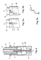
- Fig. 1 eine schematisiert dargestellte Gesamtansicht einer Ausführungsform einer erfindungsgemäßen Vorrichtung;
- Fig. 2 einen Schnitt durch die erfindungsgemäße Vorrichtung ohne den nicht dargestellten Sprühkopf;
- Fig. 3a-c schematische Detailansichten von denjenigen Vorrichtungselementen, die die stufenweise Betätigung gewährleisten, nämlich
- Fig. 3a einen in einem geraden Schlitz gleitenden Stift, von dem bestimmte Stellungen durch elastisches Einschnappen arretiert werden;
- Fig. 3b die bevorzugte Ausführungsform, bei der ein Stift in einem stufenweise ausgebildeten Schlitz gleitet, und
- Fig. 3c eine schematische Darstellung der Folge von Dreh- und Vorschubbewegungen, die zur Betätigung einer Vorrichtung mit den Elementen gemäß Fig. 3b erforderlich sind.
- 1 shows a schematically represented overall view of an embodiment of a device according to the invention;
- 2 shows a section through the device according to the invention without the spray head, not shown;
- Fig. 3a-c schematic detailed views of those device elements that ensure the gradual actuation, namely
- 3a shows a pin sliding in a straight slot, from which certain positions are locked by elastic snap-in;
- Fig. 3b, the preferred embodiment in which a pin slides in a step-shaped slot, and
- Fig. 3c is a schematic representation of the sequence of rotary and feed movements that are required to operate a device with the elements of FIG. 3b.
Bezug nehmend auf Fig. 1 besteht eine erfindungsgemäße Vorrichtung aus drei Grundelementen. Das erste ist der Ausgabekopf 1, der üblicherweise ein Sprühkopf zum Verstäuben eines Arzneimittels ist und eine Sprühdüse 1a und einen Kragen 1b aufweist, der das Festhalten des Ausgabekopfes 1 zwischen zwei Fingern erleichtert. Das zweite Grundelement ist eine Injektionsspritze 2 mit dem üblichen zugehörigen Spritzenkolben 2a. Diese Injektionsspritze 2 ist so dicht mit dem Ausgabekopf 1 verbunden, daß ein beim Eindrücken des Spritzenkolbens 2a in der Injektionsspritze 2 entwickelter Druck ohne Verlust an der Sprühdüse 1a wirksam wird. Zum Aufbau des erforderlichen Drucks hat es sich dabei als Vorteilhaft erwiesen, die Injektionsnadel auf der Injektionsspritze 2 zu belassen und den Sprühkopf um die Injektionsnadel und den Nadelansatz der Injektionsspritze 2 herum dicht anliegend anzuordnen.1, an apparatus according to the invention consists of three basic elements. The first is the dispensing
Eine aus dem Ausgabekopf 1 und der Injektionsspritze 2 bestehende Vorrichtung ermöglicht zwar bereits ein Zerstäuben des Inhalts der Injektionsspritze, jedoch keine zuverlässige Portionierung und bildet außerdem eine für ein Handelsprodukt zu zerbrechliche Struktur. Für die erfindungsgemäße Vorrichtung ist daher als drittes Grundelement noch ein Rohr 3 erforderlich, das die Injektionsspritze mit dem gezogenen Spritzenkolben gegen Knickbelastungen sowie in axialer Richtung wirkende Krafteinwirkungen zum falschen Moment schützt. Der einfachste Fall bestünde darin, die Injektionsspritze in einem am Sprühkopf befestigten Röhrchen anzuordnen, das vor Gebrauch von der Vorrichtung entfernt wird. Das schrittweise Eindrücken des Spritzenkolbens könnte dann durch an der Spritze oder auf dem gezogenen Teil des Spritzenkolbens angeordneten Anschlägen gesichert werden, beispielsweise in Form abnehmbarer Röhrchen.A device consisting of the dispensing
Gemäß der vorliegenden Erfindung wird jedoch der elegantere Weg beschritten, das Rohr 3 aus teleskopartig ineinandergreifenden Rohrteilen aufzubauen, und zwar vorzugsweise aus nur zwei Rohrteilen 3a und 3b. Sollte es aus irgendwelchen speziellen Gründen wünschenswert erscheinen, können jedoch ohne weiteres auch mehr derartige Rohrteile verwendet werden. Eines der Rohrteile 3a, das im Falle der dargestellten Ausführungsform das Rohrteil mit dem geringsten Durchmesser ist, ist ausreichend fest mit dem Ausgabekopf 1 verbunden. Das Ende dieses Rohrteils 3a ist in den Hohlraum des zweiten Rohrteils 3b eingeschoben, und zwar so, daß das Rohrteil 3b auf der Außenrohrfläche des Rohrteils 3a gleiten kann. Am Ende des Rohrteils 3b ist dieses geschlossen oder wenigstens mit Anschlägen 4 versehen, die gewährleisten, daß beim Verschieben des Rohrteils 3b gleichzeitig der Spritzenkolben 2a mit verschoben wird, das heißt, die Injektionsspritze betätigt wird. Im einfachsten bevorzugten Falle ist das Rohrteil 3b mit einem Boden 4 versehen, der die Funktion des Anschlags erfüllt. Um eine einfache Montage der gesamten Vorrichtung zu gewährleisten und ein Verkanten der Injektionsspritze während der Betätigung der Vorrichtung zu vermeiden, weisen die Rohrteile 3a und 3b geeignete Führungen auf, die eine koaxiale Anordnung der Injektionsspritze gewährleisten. In der gezeigten bevorzugten Ausführungsform wird dabei eine dieser Führungen, und zwar die im Rohrteil 3a, dadurch gebildet, daß das Rohrteil 3a ebenfalls einen Boden aufweist, in dem allerdings eine Durchgangsöffnung ausgeführt ist, durch die ohne übermäßiges Spiel der Kolben der Injektionsspritze hindurchgesteckt werden kann. Vorzugsweise weist auch das Rohrteil 3b noch eine Führung auf, wobei sich eine Führung 8, wie sie in Fig. 2 erkennbar ist, als vorteilhaft herausgestellt hat. Diese Führung 8 besteht darin, daß im verdickten Boden 4 des Rohrteils 3b eine zentrale Blindbohrung ausgeführt ist, die paßgenau das freie Ende des Spritzenkolbens aufnimmt und dieses während der Betätigung der Vorrichtung hält.According to the present invention, however, the more elegant way is taken to construct the
Ein teleskopartig zusammendrückbares Rohr muß vor Gebrauch gegen ein unbeabsichtigtes Zusammendrücken gesichert sein. Diese Sicherung kann durch entfernbare Sicherungselemente in Form von z. B. Klebestreifen gewährleistet sein, wird jedoch vorzugsweise von den gleichen Elementen übernommen, die die Größe der aus der Vorrichtung abgegebenen Portionen regeln. Diese Elemente sind vorzugsweise Vorsprünge und Vertiefungen, die an den beiden Rohrteilen angeordnet sind und im gewünschten Sinne zusammenwirken. Die Vorsprünge können dabei Stifte oder Knöpfe sein, die ggf. auch federbeaufschlagt sein können und die mit Schlitzen oder Nuten im anderen Teil zusammenwirken. Beispielsweise können elastische Knöpfe vorgesehen sein, die eingedrückt werden müssen, damit ein Vorschub des beweglichen Rohrteils 3b möglich ist. Mechanismen, wie sie z. B. von Schirmen bekannt sind, sind grundsätzlich verwendbar. Ferner ist es möglich, die Vorsprünge 7 und Aussparungen 6 so zu gestalten, wie in Fig. 3a dargestellt ist. In diesem Falle stellt die Aussparung einen geraden Schlitz dar, in dem ein Stift 7 gleiten kann. Stift 7 und Aussparung 6 bilden somit auf jeden Fall eine Führung für den geraden Vorschub des beweglichen Rohrteils 3b. Um bestimmte Stellungen des Rohrteils 3b zu fixieren, können in dem Schlitz 6 Nasen angeordnet sein, die den Stift 7 zwischen sich fangen, wenn er durch den Schlitz gleitet.A telescopically compressible tube must be secured against unintentional compression before use. This fuse can be removed by removable fuse elements in the form of z. B. adhesive strips can be guaranteed, but is preferably taken over by the same elements that regulate the size of the portions dispensed from the device. These elements are preferably projections and depressions which are arranged on the two tube parts and cooperate in the desired sense. The projections can be pins or buttons, which can optionally also be spring-loaded and which interact with slots or grooves in the other part. For example, elastic buttons can be provided which have to be pressed in so that the movable
Eine solche Ausführungsform kann jedoch bei einer zu großen Krafteinwirkung dazu führen, daß das bewegliche Rohrteil 3b ungewollt zu weit eingedrückt wird. Das ist bei der bevorzugten Ausführungsform gemäß Fig. 3b jedoch ausgeschlossen. In diesem Falle ist der Schlitz 16 stufenförmig ausgestaltet. In der Ausgangsstellung wird der Stift 7 in einer Erweiterung des Schlitzes 16 gehalten. Gegen ein Herausziehen aus dem Schlitz ist er durch eine eine Verengung des Schlitzes bildende, elastisch überwindbare Nase gehalten. Ein Eindrücken des Rohrteils 3b wird durch eine Stufe sicher verhindert. Um die Vorrichtung betätigen zu können, muß, wie in Fig. 3c schematisch dargestellt ist, das Rohrteil 3b gegen das Rohrteil 3a gedreht werden, wobei vorzugsweise ein Widerstand in Form einer elastischen Nase 19 zu überwinden ist. Diese Drehung (a in Fig. 3c) ermöglicht anschließend ein Eindrücken des Rohrteils 3b über die Länge des geraden Schlitzabschnitts bis zur nächsten Stufe (3b in Fig. 3c). Eine Wiederholung dieser Bewegungen (c und d in Fig. 3c) ermöglicht dann ein vollständiges Aufschieben des Rohrteils 3b und damit gleichzeitig vollständiges Eindrücken des vorher gezogenen Spritzenkolbens. Auf diese Weise wird der Inhalt des Spritzenkolbens in zwei gleichen Portionen versprüht, deren Größe durch die Länge der geraden Abschnitte des stufenförmigen Schlitzes 16 vorgegeben ist. Selbstverständlich ist ein Versprühen in mehr Portionen möglich, wenn mehr Stufen vorgesehen werden.Such an embodiment, however, can result in excessive force when the
Die Erfindung wurde vorstehend unter Bezugnahme auf konkrete Ausführungsbeispiele geschildert. Insbesondere was die Ge staltung des teleskopartig zusammendrückbaren Rohres 3 angeht, sind jedoch zahlreiche, für den Fachmann offensichtlich äquivalente Ausführungsformen denkbar. So können die Rohrteile 3a und 3b auch so angeordnet werden, daß das hintere Rohrteil den kleineren Durchmesser aufweist. Stifte und Schlitze können ebenfalls vertauscht angeordnet werden, und für die koaxiale Halterung der Injektionsspritze in den Röhrchen sind zahlreiche andere Ausführungsformen der Führungselemente denkbar, die außerdem auch noch zusätzlich zu den geschilderten verwendet werden können.The invention has been described above with reference to specific exemplary embodiments. In particular what the Ge Design of the telescopically
Als Sprühköpfe können handelsübliche, für die intranasale Verabreichung von flüssigen Arzneimitteln bestimmte Sprühköpfe verwendet werden. Derartige Sprühköpfe werden normalerweise in Verbindung mit einer Pumpe verwendet und sind einfache Kunststoff-Spritzgußteile mit einem engen zentralen Flüssigkeitskanal und einer Vernebelungsdüse. Derartige Sprühköpfe können beispielsweise bei der Firma Ing. Erich Pfeiffer GmbH & Co. KG, D-7760 Radolfszell, Bundesrepublik Deutschland, bezogen werden. Sie können gegebenenfalls etwas abgewandelt sein, damit die Spritzennadel dicht vom Flüssigkeitskanal umschlossen wird und genau bis in den Bereich unter der Vernebelungsdüse reicht.Commercially available spray heads intended for intranasal administration of liquid medicaments can be used as spray heads. Such spray heads are normally used in conjunction with a pump and are simple plastic injection molded parts with a narrow central liquid channel and a nebulizing nozzle. Such spray heads can be obtained, for example, from Ing. Erich Pfeiffer GmbH & Co. KG, D-7760 Radolfszell, Federal Republic of Germany. If necessary, they can be modified so that the syringe needle is tightly enclosed by the liquid channel and extends exactly into the area under the nebulization nozzle.
Obwohl die vorliegende Erfindung für die portionsweise intranasale Verabreichung eines bestimmten Präparats gemacht wurde, sind ohne weiteres auch andere Einsatzmöglichkeiten denkbar. So kann eine erfindungsgemäße Vorrichtung auch einfach zum Vertrieb gefüllter Injektionsspritzen für die verschiedensten Zwecke verwendet werden, wobei in diesem Falle der Ausgabekopf durch eine einfache Schutzkappe zu ersetzen wäre. Eine entsprechende Gestaltung der Ausgabeöffnung vorausgesetzt, kann die Vorrichtung auch für die tropfenweise Verabreichung von Medikamenten, z. B. antibiotikahaltige Augentropfen, ausgestaltet werden. Ferner ist ein Versprühen nicht nur in die Nasenöffnungen möglich, sondern auch in beliebige andere Körperöffnungen, z. B. den Rachenraum. Soweit für derartige Verwendungszwecke die wesentlichen Merkmale einer erfindungsgemäßen Vorrichtung verwendet werden, sollen derartige Abwandlungen als Benutzungen der geschützten Vorrichtung angesehen werden.Although the present invention was made for the intranasal administration of a certain preparation in portions, other possible uses are also conceivable. Thus, a device according to the invention can also be used simply for the sale of filled injection syringes for a wide variety of purposes, in which case the dispensing head would have to be replaced by a simple protective cap. Provided that the dispensing opening is designed accordingly, the device can also be used for the dropwise administration of medicaments, e.g. B. antibiotic eye drops, are designed. Furthermore, spraying is possible not only into the nostrils, but also into any other body openings, e.g. B. the pharynx. So far for such If the essential features of a device according to the invention are used, such modifications should be regarded as uses of the protected device.
Claims (10)
- einen Ausgabekopf (1) mit einer Ausgabedüse (1a), der
- mit dem nadelseitigen Ende einer Injektionsspritze (2) dicht verbunden ist, wobei diese Injektionsspritze (2)
- mit gezogenem Spritzenkolben (2a) gefüllt in einem Röhrchen (3) angeordnet ist, das mit dem Ausgabekopf (1) verbunden ist.1. Device for the metered administration of a liquid drug, characterized by
- An output head (1) with an output nozzle (1a), the
- Is tightly connected to the needle-side end of an injection syringe (2), said injection syringe (2)
- Filled with drawn syringe plunger (2a) in a tube (3) which is connected to the dispensing head (1).
- von denen ein erstes Rohrteil (3a) mit dem Ausgabekopf (1) verbunden ist,
- und ein anderes Rohrteil (3b) einen Anschlag (4) für das Ende des Spritzenkolbens (2a) aufweist, so daß dieser beim teleskopartigen Ineinanderschieben der Rohrteile (3a, 3b) eingedrückt wird,
- und die Rohrteile (3a, 3b) mit zusammenwirkenden Aussparungen (6) und Vorsprüngen (7) versehen sind, die den gestreckten Zustand des Röhrchens (3) sowie vorzugsweise mindestens eine Zwischenstellung vor dem völlig eingedrückten Zustand fixieren.4. Device according to one of claims 1 to 3, characterized in that the tube (3) consists of at least two telescopically telescopic pipe parts (3a, 3b),
- Of which a first pipe part (3a) is connected to the dispensing head (1),
- And another pipe part (3b) has a stop (4) for the end of the syringe plunger (2a), so that it is pressed in when telescoping the pipe parts (3a, 3b),
- And the tube parts (3a, 3b) are provided with cooperating recesses (6) and projections (7) which fix the stretched state of the tube (3) and preferably at least one intermediate position before the fully pressed-in state.
Priority Applications (1)
| Application Number | Priority Date | Filing Date | Title |
|---|---|---|---|
| AT89105231T ATE72630T1 (en) | 1988-03-25 | 1989-03-23 | DEVICE FOR DOSED ADMINISTRATION OF A LIQUID MEDICATION. |
Applications Claiming Priority (2)
| Application Number | Priority Date | Filing Date | Title |
|---|---|---|---|
| DE3810262 | 1988-03-25 | ||
| DE3810262A DE3810262A1 (en) | 1988-03-25 | 1988-03-25 | DEVICE FOR THE DOSED ADMINISTRATION OF A LIQUID MEDICINAL PRODUCT |
Publications (2)
| Publication Number | Publication Date |
|---|---|
| EP0334349A1 true EP0334349A1 (en) | 1989-09-27 |
| EP0334349B1 EP0334349B1 (en) | 1992-02-19 |
Family
ID=6350750
Family Applications (1)
| Application Number | Title | Priority Date | Filing Date |
|---|---|---|---|
| EP89105231A Expired - Lifetime EP0334349B1 (en) | 1988-03-25 | 1989-03-23 | Device for the dosed application of a liquid drug |
Country Status (7)
| Country | Link |
|---|---|
| US (1) | US4962868A (en) |
| EP (1) | EP0334349B1 (en) |
| JP (1) | JPH0211158A (en) |
| AT (1) | ATE72630T1 (en) |
| DE (2) | DE3810262A1 (en) |
| ES (1) | ES2030930T3 (en) |
| GR (1) | GR3003848T3 (en) |
Cited By (11)
| Publication number | Priority date | Publication date | Assignee | Title |
|---|---|---|---|---|
| WO1991013689A1 (en) * | 1990-03-14 | 1991-09-19 | Ing. Erich Pfeiffer Gmbh & Co. Kg | Applicator for media |
| WO1992000812A1 (en) * | 1990-07-04 | 1992-01-23 | Ing. Erich Pfeiffer Gmbh & Co. Kg | Dispensing device for media |
| EP0486894A1 (en) * | 1990-11-21 | 1992-05-27 | Promo Pack Sa | Single-dose spray-dispenser for endonasal adminstration of liquid medicaments |
| US5601077A (en) * | 1991-08-07 | 1997-02-11 | Becton, Dickinson And Company | Nasal syringe sprayer with removable dose limiting structure |
| EP1084763A2 (en) | 1999-09-15 | 2001-03-21 | Ing. Erich Pfeiffer GmbH | Dispenser for dispensing, in particular spraying, a fluid from a container |
| EP1084765A2 (en) | 1999-09-15 | 2001-03-21 | Ing. Erich Pfeiffer GmbH | Apparatus for dispensing, in particular for spraying fluid |
| US6530371B2 (en) | 1999-10-14 | 2003-03-11 | Becton, Dickinson And Company | Drug delivery system including holder and drug container |
| US7296566B2 (en) | 1999-10-14 | 2007-11-20 | Becton, Dickinson And Company | Nasal delivery device including spray nozzle |
| WO2008059385A2 (en) * | 2006-11-16 | 2008-05-22 | Becton Dickinson France | Device for automatic delivery of successive doses of product |
| WO2009066164A1 (en) | 2007-11-23 | 2009-05-28 | Lameplast S.P.A. | Cannula for dispensing fluid products, particularly for rectal applications |
| DE102008027147A1 (en) * | 2008-06-02 | 2009-12-03 | Ing. Erich Pfeiffer Gmbh | Discharge device for media |
Families Citing this family (65)
| Publication number | Priority date | Publication date | Assignee | Title |
|---|---|---|---|---|
| DE4016126A1 (en) * | 1990-04-17 | 1991-10-24 | Coster Tecnologie Speciali Spa | DEVICE FOR TRANSNASAL OR ORAL ADMINISTRATION OF MEDICATIONS OR THE LIKE |
| DE4030530A1 (en) * | 1990-09-27 | 1992-04-02 | Pfeiffer Erich Gmbh & Co Kg | DISCHARGE DEVICE FOR MEDIA |
| AU9169891A (en) * | 1990-12-14 | 1992-07-08 | Habley Medical Technology Corporation | Variable proportion dispenser |
| US5240146A (en) * | 1990-12-14 | 1993-08-31 | Smedley William H | Variable proportion dispenser |
| US5331954A (en) * | 1990-12-21 | 1994-07-26 | Novo Nordisk A/S | Device for nasal delivery of liquid medications |
| DK302890D0 (en) * | 1990-12-21 | 1990-12-21 | Novo Nordisk As | DISPENSER |
| FR2675404B1 (en) * | 1991-04-16 | 1993-07-23 | Valois | DEVICE FOR SPRAYING OR DISPENSING A FLUID PRODUCT, WITH IMPROVED OPERATING SECURITY. |
| DE4123330A1 (en) * | 1991-07-15 | 1993-01-21 | Gerhard Netz | Per-anal bacteria introduction system for regeneration of bowel bacteria - includes accommodating bacteria in water-soluble, pref. gelatin casing prior to insertion via sleeve |
| IT1253173B (en) * | 1991-08-02 | 1995-07-10 | Rosaria Galli | ENDONASAL CONTAINER-NEBULIZER WITH A SERVO-DISPENSING DEVICE INCORPORATED TO ENSURE THE EFFECTIVE ADMINISTRATION IN TWO TIMES. |
| GB9125699D0 (en) * | 1991-12-03 | 1992-01-29 | Glaxo Group Ltd | Device |
| JPH05224476A (en) * | 1991-12-20 | 1993-09-03 | Canon Inc | Process cartridge and image forming device capable of loading the same |
| US5271527A (en) * | 1992-04-02 | 1993-12-21 | Habley Medical Technology Corporation | Reusable pharmaceutical dispenser with full stroke indicator |
| US5253785A (en) * | 1992-04-02 | 1993-10-19 | Habley Medical Technology Corp. | Variable proportion dispenser |
| US5423752A (en) * | 1992-07-31 | 1995-06-13 | Habley Medical Technology Corporation | Variable proportion dispenser with cartridge replacement assembly |
| US5443447A (en) * | 1992-09-24 | 1995-08-22 | Amin I. Kassis | Intracavitary delivery or withdrawal device |
| GB2272389B (en) * | 1992-11-04 | 1996-07-24 | Bespak Plc | Dispensing apparatus |
| US5378233A (en) * | 1992-11-18 | 1995-01-03 | Habley Medical Technology Corporation | Selected dose pharmaceutical dispenser |
| GB9311892D0 (en) * | 1993-06-09 | 1993-07-28 | Glaxo Wellcome Australia Ltd | Device |
| US5836359A (en) * | 1995-06-30 | 1998-11-17 | Concept Workshop Worldwide, Llc | Liquid dosage dispensers |
| US6045003A (en) * | 1995-06-30 | 2000-04-04 | Concept Workshop Worldwide, Llc | Liquid dosage dispensers |
| GB2316451B (en) * | 1996-08-15 | 2000-09-13 | Tenax Corp | Dispensing device |
| US5951526A (en) | 1997-09-24 | 1999-09-14 | Korisch; Marina | Syringe holder with integral dose divider |
| US5783254A (en) * | 1997-09-29 | 1998-07-21 | Maynard; Robert G. | Paint applicator method |
| US6083201A (en) | 1999-01-07 | 2000-07-04 | Mckinley Medical, Llp | Multi-dose infusion pump |
| US6348043B1 (en) | 1998-12-29 | 2002-02-19 | Mckinley Medical, Lllp | Multi-dose infusion pump providing minimal flow between doses |
| US6382205B1 (en) * | 1999-11-02 | 2002-05-07 | Robert E. Weinstein | Method and device for organizing and coordinating the combined use of topical agents for the treatment of respiratory disorders |
| DE10109671C1 (en) * | 2001-02-28 | 2002-05-02 | Draeger Medical Ag | Device for delivering gas to a ventilator |
| DE10036594A1 (en) * | 2000-07-27 | 2002-02-07 | Pfeiffer Erich Gmbh & Co Kg | Delivery unit, especially for pharmaceuticals, comprises a container composed of separate chambers which hold a media component, an actuating unit and a connection between the chambers |
| FR2817245B1 (en) * | 2000-11-30 | 2003-05-02 | Valois Sa | FLUID PRODUCT DISPENSING DEVICE |
| US6443152B1 (en) * | 2001-01-12 | 2002-09-03 | Becton Dickinson And Company | Medicament respiratory delivery device |
| US6722364B2 (en) | 2001-01-12 | 2004-04-20 | Becton, Dickinson And Company | Medicament inhalation delivery devices and methods for using the same |
| US6644309B2 (en) | 2001-01-12 | 2003-11-11 | Becton, Dickinson And Company | Medicament respiratory delivery device and method |
| JP4911867B2 (en) * | 2001-04-10 | 2012-04-04 | ベクトン・ディキンソン・アンド・カンパニー | Drug delivery system including holder and drug container |
| WO2003028785A2 (en) | 2001-10-03 | 2003-04-10 | Medical Instill Technologies, Inc. | Syringe and reconstitution syringe |
| US7798185B2 (en) | 2005-08-01 | 2010-09-21 | Medical Instill Technologies, Inc. | Dispenser and method for storing and dispensing sterile food product |
| US6957752B2 (en) | 2001-10-16 | 2005-10-25 | Medical Instill Technologies, Inc. | Dispenser with sealed chamber and one-way valve for providing metered amounts of substances |
| US6620405B2 (en) * | 2001-11-01 | 2003-09-16 | 3M Innovative Properties Company | Delivery of hydrogel compositions as a fine mist |
| DE60334633D1 (en) | 2002-08-13 | 2010-12-02 | Medical Instill Tech Inc | CONTAINER AND VALVE ASSEMBLY FOR STORING AND DISPENSING SUBSTANCES AND RELATED METHOD |
| FR2845016B1 (en) | 2002-09-27 | 2004-12-03 | Becton Dickinson France | SPRAYING OR INJECTION DEVICE FOR DELIVERING AT LEAST TWO SPECIFIED DOSES OF PRODUCT |
| US20050087556A1 (en) * | 2002-12-02 | 2005-04-28 | Cesare Signorini | Metering device for syrups and other fluids |
| DE10322354A1 (en) * | 2003-04-11 | 2004-10-28 | Hilti Corporation | Hand-held dispenser pump for pasty or highly viscous adhesive has pump chamber with flexible walls which allow reduction in volume and telescopic two-part housing |
| WO2004101027A2 (en) | 2003-05-12 | 2004-11-25 | Medical Instill Technologies, Inc. | Dispenser and apparatus for fillling a dispenser |
| US7226231B2 (en) | 2003-07-17 | 2007-06-05 | Medical Instill Technologies, Inc. | Piston-type dispenser with one-way valve for storing and dispensing metered amounts of substances |
| DE10340585A1 (en) * | 2003-09-03 | 2005-04-07 | Tecpharma Licensing Ag | Administration device with multi-chamber ampoule and mixing stop |
| US7264142B2 (en) | 2004-01-27 | 2007-09-04 | Medical Instill Technologies, Inc. | Dispenser having variable-volume storage chamber and depressible one-way valve assembly for dispensing creams and other substances |
| US7520406B2 (en) * | 2005-07-08 | 2009-04-21 | S. C. Johnson & Son, Inc. | Device for dispensing a controlled dose of a flowable material |
| US20100036361A1 (en) * | 2008-06-20 | 2010-02-11 | Pulmonx | System and method for delivering multiple implants into lung passageways |
| US8851339B2 (en) * | 2009-02-19 | 2014-10-07 | S.C. Johnson & Son, Inc. | Applicator for self-adhesive products |
| US9480804B2 (en) * | 2009-12-23 | 2016-11-01 | Becton, Dickinson And Company | Monodose nasal drug delivery system |
| WO2011105644A1 (en) * | 2010-02-26 | 2011-09-01 | Yoo Byung Eun | Portable enema device |
| FR2959215B1 (en) * | 2010-04-22 | 2013-09-06 | Qualipac Sa | FLUID PRODUCT DISPENSER WITH RETRACTABLE HEAD |
| EP2589402B1 (en) * | 2010-06-30 | 2018-07-25 | Nipro Corporation | Spraying device |
| US20120160872A1 (en) * | 2010-12-27 | 2012-06-28 | Anne Berg Co., Ltd. | Pump structure for dispenser |
| WO2012119262A1 (en) * | 2011-03-04 | 2012-09-13 | Hoffmann Neopac Ag | Medical device for dispensing a medical or pharmaceutical product |
| JPWO2012147862A1 (en) * | 2011-04-26 | 2014-07-28 | 参天製薬株式会社 | Metered discharge container |
| US9114911B2 (en) | 2012-10-19 | 2015-08-25 | Owens-Brockway Glass Container Inc. | Container, handle for a container, and handle and container assembly |
| FR3016304B1 (en) * | 2014-01-13 | 2018-03-09 | Aptar France Sas | FLUID PRODUCT DISPENSING ASSEMBLY AND METHOD OF USING SUCH ASSEMBLY. |
| CN106535970A (en) * | 2014-05-28 | 2017-03-22 | 赛诺菲股份有限公司 | Assembly for a counter mechanism for a drug delivery device and drug delivery device |
| CN109966631A (en) * | 2019-04-22 | 2019-07-05 | 张璐 | A kind of portable sensible lotion device |
| WO2020264017A1 (en) | 2019-06-24 | 2020-12-30 | INdev, LLC | Nasal medication or drug delivery devices and methods |
| US11161657B2 (en) | 2019-11-25 | 2021-11-02 | Berlin Packaging, Llc | Child resistant senior friendly bottle packaging for liquids |
| US10875688B1 (en) | 2019-11-25 | 2020-12-29 | Berlin Packaging, Llc | Child resistant senior friendly bottle packaging for liquids |
| EP4208222A1 (en) * | 2020-09-01 | 2023-07-12 | Janssen Pharmaceutica N.V. | Drug syringes with a mechanical stop for a second dose |
| USD1012725S1 (en) | 2020-10-07 | 2024-01-30 | Berlin Packaging, Llc | Dosing container |
| FR3141857A1 (en) * | 2022-11-14 | 2024-05-17 | Aptar France Sas | Fluid product dispensing device |
Citations (1)
| Publication number | Priority date | Publication date | Assignee | Title |
|---|---|---|---|---|
| US4127126A (en) * | 1976-11-11 | 1978-11-28 | Schunk George J | Oral dispensing device |
Family Cites Families (9)
| Publication number | Priority date | Publication date | Assignee | Title |
|---|---|---|---|---|
| US963051A (en) * | 1910-02-10 | 1910-07-05 | Robert A Kooken | Ointment-applier. |
| US1269922A (en) * | 1918-04-11 | 1918-06-18 | Frank Gadecki | Gun. |
| US1742157A (en) * | 1927-02-14 | 1929-12-31 | Christian Thomas | Dispensing device |
| US2250758A (en) * | 1939-06-13 | 1941-07-29 | Charles P French | Fountain toothbrush |
| US2434875A (en) * | 1945-08-11 | 1948-01-20 | Turnbull | Jetting device |
| US2648334A (en) * | 1949-10-28 | 1953-08-11 | Turnbull | Hypodermic injection assembly |
| US4091812A (en) * | 1976-01-19 | 1978-05-30 | Alcon Laboratories, Inc. | Operator means for syringe cartridges |
| US4475905A (en) * | 1982-09-30 | 1984-10-09 | Himmelstrup Anders B | Injection device |
| DK172984D0 (en) * | 1984-03-30 | 1984-03-30 | Novo Industri As | DISPENSER |
-
1988
- 1988-03-25 DE DE3810262A patent/DE3810262A1/en active Granted
-
1989
- 1989-03-21 US US07/326,389 patent/US4962868A/en not_active Expired - Lifetime
- 1989-03-23 EP EP89105231A patent/EP0334349B1/en not_active Expired - Lifetime
- 1989-03-23 AT AT89105231T patent/ATE72630T1/en not_active IP Right Cessation
- 1989-03-23 DE DE8989105231T patent/DE58900829D1/en not_active Expired - Lifetime
- 1989-03-23 ES ES198989105231T patent/ES2030930T3/en not_active Expired - Lifetime
- 1989-03-24 JP JP1073714A patent/JPH0211158A/en active Pending
-
1992
- 1992-02-20 GR GR910401725T patent/GR3003848T3/el unknown
Patent Citations (1)
| Publication number | Priority date | Publication date | Assignee | Title |
|---|---|---|---|---|
| US4127126A (en) * | 1976-11-11 | 1978-11-28 | Schunk George J | Oral dispensing device |
Cited By (23)
| Publication number | Priority date | Publication date | Assignee | Title |
|---|---|---|---|---|
| WO1991013689A1 (en) * | 1990-03-14 | 1991-09-19 | Ing. Erich Pfeiffer Gmbh & Co. Kg | Applicator for media |
| WO1992000812A1 (en) * | 1990-07-04 | 1992-01-23 | Ing. Erich Pfeiffer Gmbh & Co. Kg | Dispensing device for media |
| EP0486894A1 (en) * | 1990-11-21 | 1992-05-27 | Promo Pack Sa | Single-dose spray-dispenser for endonasal adminstration of liquid medicaments |
| US5289818A (en) * | 1990-11-21 | 1994-03-01 | Promo Pack S.A. | Single-dose spray-dispenser for endonasal administration of liquid medicaments |
| US5601077A (en) * | 1991-08-07 | 1997-02-11 | Becton, Dickinson And Company | Nasal syringe sprayer with removable dose limiting structure |
| US6382465B1 (en) | 1999-09-15 | 2002-05-07 | Ing. Ercih Pfeiffer Gmbh | Dispenser for the optionally atomized discharge of an in particular liquid medium from a container |
| EP1745855A3 (en) * | 1999-09-15 | 2008-11-05 | Ing. Erich Pfeiffer GmbH | Dispenser for dispensing, in particular spraying, a fluid from a container |
| DE19944209A1 (en) * | 1999-09-15 | 2001-03-22 | Pfeiffer Erich Gmbh & Co Kg | Dispenser for possibly atomizing the discharge of a medium, in particular a liquid, from a container |
| DE19944211A1 (en) * | 1999-09-15 | 2001-03-22 | Pfeiffer Erich Gmbh & Co Kg | Device for the optionally atomized application of an in particular liquid medium |
| EP1084763A3 (en) * | 1999-09-15 | 2001-11-21 | Ing. Erich Pfeiffer GmbH | Dispenser for dispensing, in particular spraying, a fluid from a container |
| EP1084763A2 (en) | 1999-09-15 | 2001-03-21 | Ing. Erich Pfeiffer GmbH | Dispenser for dispensing, in particular spraying, a fluid from a container |
| US6427878B1 (en) | 1999-09-15 | 2002-08-06 | Ing. Erich Pfeiffer Gmbh | Apparatus for the discharge of an atomized liquid medium in partial strokes of different length |
| EP1084765A2 (en) | 1999-09-15 | 2001-03-21 | Ing. Erich Pfeiffer GmbH | Apparatus for dispensing, in particular for spraying fluid |
| EP1745855A2 (en) | 1999-09-15 | 2007-01-24 | Ing. Erich Pfeiffer GmbH | Dispenser for dispensing, in particular spraying, a fluid from a container |
| US7296566B2 (en) | 1999-10-14 | 2007-11-20 | Becton, Dickinson And Company | Nasal delivery device including spray nozzle |
| US6530371B2 (en) | 1999-10-14 | 2003-03-11 | Becton, Dickinson And Company | Drug delivery system including holder and drug container |
| WO2008059385A2 (en) * | 2006-11-16 | 2008-05-22 | Becton Dickinson France | Device for automatic delivery of successive doses of product |
| FR2908753A1 (en) * | 2006-11-16 | 2008-05-23 | Becton Dickinson France Soc Pa | DEVICE FOR AUTOMATICALLY DELIVERING SUCCESSIVE PRODUCT DOSES |
| WO2008059385A3 (en) * | 2006-11-16 | 2008-09-12 | Becton Dickinson France | Device for automatic delivery of successive doses of product |
| US8568358B2 (en) | 2006-11-16 | 2013-10-29 | Becton Dickinson France | Device for automatic delivery of successive doses of product |
| WO2009066164A1 (en) | 2007-11-23 | 2009-05-28 | Lameplast S.P.A. | Cannula for dispensing fluid products, particularly for rectal applications |
| DE102008027147A1 (en) * | 2008-06-02 | 2009-12-03 | Ing. Erich Pfeiffer Gmbh | Discharge device for media |
| US8162183B2 (en) | 2008-06-02 | 2012-04-24 | Ing. Erich Pfeiffer Gmbh | Dispensing device for media |
Also Published As
| Publication number | Publication date |
|---|---|
| DE3810262C2 (en) | 1991-04-25 |
| JPH0211158A (en) | 1990-01-16 |
| EP0334349B1 (en) | 1992-02-19 |
| ATE72630T1 (en) | 1992-03-15 |
| DE58900829D1 (en) | 1992-03-26 |
| DE3810262A1 (en) | 1989-10-12 |
| ES2030930T3 (en) | 1992-11-16 |
| US4962868A (en) | 1990-10-16 |
| GR3003848T3 (en) | 1993-03-16 |
Similar Documents
| Publication | Publication Date | Title |
|---|---|---|
| EP0334349B1 (en) | Device for the dosed application of a liquid drug | |
| DE3645245C2 (en) | Injection appliance | |
| DE10229138B4 (en) | Product diverter with piston rod emergency reset | |
| EP1525015B1 (en) | Administration device comprising a priming function | |
| EP1416982B1 (en) | Locking device for connecting housing sections of an administration appliance | |
| EP2252350B1 (en) | Administering apparatus comprising a blockable actuation element | |
| EP1988952B1 (en) | Injection device with secured dosing button | |
| DE10106367B4 (en) | A reading aid for a device for administering an adjustable dose of an injectable product | |
| EP1642094A2 (en) | Device for administering a liquid product | |
| WO2003011374A1 (en) | Administration device secured against rotation | |
| DE102007026560A1 (en) | Delivery device with axially movable indicator | |
| WO2003011372A2 (en) | Reservoir module with a piston rod | |
| EP1711218A2 (en) | Injection device with an improved dosing member | |
| WO2008031239A1 (en) | Injection device comprising several coupling mechanisms | |
| DE102006004563A1 (en) | Injection device for administering medication has a casing, a delivery element moving in relation to the casing and a locking element | |
| EP1981570B1 (en) | Pusher with a coupling element | |
| WO2004006997A1 (en) | Administration device comprising a plunger rod with a return lock | |
| EP3263159B1 (en) | Injection device with an improved metering member and a pre-tensioned ejection spring | |
| WO2011029468A1 (en) | Device for administering an injectable product having a discharge counter |
Legal Events
| Date | Code | Title | Description |
|---|---|---|---|
| PUAI | Public reference made under article 153(3) epc to a published international application that has entered the european phase |
Free format text: ORIGINAL CODE: 0009012 |
|
| AK | Designated contracting states |
Kind code of ref document: A1 Designated state(s): AT BE CH DE ES FR GB GR IT LI LU NL SE |
|
| 17P | Request for examination filed |
Effective date: 19891025 |
|
| 17Q | First examination report despatched |
Effective date: 19910508 |
|
| GRAA | (expected) grant |
Free format text: ORIGINAL CODE: 0009210 |
|
| ITF | It: translation for a ep patent filed |
Owner name: UFFICIO TECNICO ING. A. MANNUCCI |
|
| AK | Designated contracting states |
Kind code of ref document: B1 Designated state(s): AT BE CH DE ES FR GB GR IT LI LU NL SE |
|
| REF | Corresponds to: |
Ref document number: 72630 Country of ref document: AT Date of ref document: 19920315 Kind code of ref document: T |
|
| GBT | Gb: translation of ep patent filed (gb section 77(6)(a)/1977) | ||
| REF | Corresponds to: |
Ref document number: 58900829 Country of ref document: DE Date of ref document: 19920326 |
|
| ET | Fr: translation filed | ||
| REG | Reference to a national code |
Ref country code: ES Ref legal event code: FG2A Ref document number: 2030930 Country of ref document: ES Kind code of ref document: T3 |
|
| REG | Reference to a national code |
Ref country code: GR Ref legal event code: FG4A Free format text: 3003848 |
|
| PLBE | No opposition filed within time limit |
Free format text: ORIGINAL CODE: 0009261 |
|
| STAA | Information on the status of an ep patent application or granted ep patent |
Free format text: STATUS: NO OPPOSITION FILED WITHIN TIME LIMIT |
|
| 26N | No opposition filed | ||
| EPTA | Lu: last paid annual fee | ||
| EAL | Se: european patent in force in sweden |
Ref document number: 89105231.8 |
|
| REG | Reference to a national code |
Ref country code: GB Ref legal event code: IF02 |
|
| PGFP | Annual fee paid to national office [announced via postgrant information from national office to epo] |
Ref country code: SE Payment date: 20030224 Year of fee payment: 15 Ref country code: GR Payment date: 20030224 Year of fee payment: 15 Ref country code: LU Payment date: 20030224 Year of fee payment: 15 Ref country code: AT Payment date: 20030224 Year of fee payment: 15 |
|
| PGFP | Annual fee paid to national office [announced via postgrant information from national office to epo] |
Ref country code: GB Payment date: 20030225 Year of fee payment: 15 Ref country code: CH Payment date: 20030225 Year of fee payment: 15 |
|
| PGFP | Annual fee paid to national office [announced via postgrant information from national office to epo] |
Ref country code: BE Payment date: 20030227 Year of fee payment: 15 |
|
| PGFP | Annual fee paid to national office [announced via postgrant information from national office to epo] |
Ref country code: NL Payment date: 20030306 Year of fee payment: 15 |
|
| PGFP | Annual fee paid to national office [announced via postgrant information from national office to epo] |
Ref country code: ES Payment date: 20030321 Year of fee payment: 15 |
|
| PGFP | Annual fee paid to national office [announced via postgrant information from national office to epo] |
Ref country code: FR Payment date: 20030326 Year of fee payment: 15 |
|
| PG25 | Lapsed in a contracting state [announced via postgrant information from national office to epo] |
Ref country code: AT Free format text: LAPSE BECAUSE OF NON-PAYMENT OF DUE FEES Effective date: 20040323 Ref country code: GB Free format text: LAPSE BECAUSE OF NON-PAYMENT OF DUE FEES Effective date: 20040323 Ref country code: LU Free format text: LAPSE BECAUSE OF NON-PAYMENT OF DUE FEES Effective date: 20040323 |
|
| PG25 | Lapsed in a contracting state [announced via postgrant information from national office to epo] |
Ref country code: SE Free format text: LAPSE BECAUSE OF NON-PAYMENT OF DUE FEES Effective date: 20040324 Ref country code: ES Free format text: LAPSE BECAUSE OF NON-PAYMENT OF DUE FEES Effective date: 20040324 |
|
| PG25 | Lapsed in a contracting state [announced via postgrant information from national office to epo] |
Ref country code: LI Free format text: LAPSE BECAUSE OF NON-PAYMENT OF DUE FEES Effective date: 20040331 Ref country code: CH Free format text: LAPSE BECAUSE OF NON-PAYMENT OF DUE FEES Effective date: 20040331 Ref country code: BE Free format text: LAPSE BECAUSE OF NON-PAYMENT OF DUE FEES Effective date: 20040331 |
|
| BERE | Be: lapsed |
Owner name: *HENNING BERLIN G.M.B.H. CHEMIE- UND PHARMAWERK Effective date: 20040331 |
|
| PG25 | Lapsed in a contracting state [announced via postgrant information from national office to epo] |
Ref country code: NL Free format text: LAPSE BECAUSE OF NON-PAYMENT OF DUE FEES Effective date: 20041001 |
|
| PG25 | Lapsed in a contracting state [announced via postgrant information from national office to epo] |
Ref country code: GR Free format text: LAPSE BECAUSE OF NON-PAYMENT OF DUE FEES Effective date: 20041006 |
|
| EUG | Se: european patent has lapsed | ||
| GBPC | Gb: european patent ceased through non-payment of renewal fee |
Effective date: 20040323 |
|
| REG | Reference to a national code |
Ref country code: CH Ref legal event code: PL |
|
| PG25 | Lapsed in a contracting state [announced via postgrant information from national office to epo] |
Ref country code: FR Free format text: LAPSE BECAUSE OF NON-PAYMENT OF DUE FEES Effective date: 20041130 |
|
| NLV4 | Nl: lapsed or anulled due to non-payment of the annual fee |
Effective date: 20041001 |
|
| REG | Reference to a national code |
Ref country code: FR Ref legal event code: ST |
|
| PG25 | Lapsed in a contracting state [announced via postgrant information from national office to epo] |
Ref country code: IT Free format text: LAPSE BECAUSE OF NON-PAYMENT OF DUE FEES;WARNING: LAPSES OF ITALIAN PATENTS WITH EFFECTIVE DATE BEFORE 2007 MAY HAVE OCCURRED AT ANY TIME BEFORE 2007. THE CORRECT EFFECTIVE DATE MAY BE DIFFERENT FROM THE ONE RECORDED. Effective date: 20050323 |
|
| REG | Reference to a national code |
Ref country code: ES Ref legal event code: FD2A Effective date: 20040324 |
|
| PGFP | Annual fee paid to national office [announced via postgrant information from national office to epo] |
Ref country code: DE Payment date: 20080407 Year of fee payment: 20 |