EP0332724B1 - Gas drying method - Google Patents
Gas drying method Download PDFInfo
- Publication number
- EP0332724B1 EP0332724B1 EP19880104106 EP88104106A EP0332724B1 EP 0332724 B1 EP0332724 B1 EP 0332724B1 EP 19880104106 EP19880104106 EP 19880104106 EP 88104106 A EP88104106 A EP 88104106A EP 0332724 B1 EP0332724 B1 EP 0332724B1
- Authority
- EP
- European Patent Office
- Prior art keywords
- tower
- air
- dry air
- drying
- desiccant
- Prior art date
- Legal status (The legal status is an assumption and is not a legal conclusion. Google has not performed a legal analysis and makes no representation as to the accuracy of the status listed.)
- Expired - Lifetime
Links
- 238000001035 drying Methods 0.000 title claims description 38
- 238000010926 purge Methods 0.000 claims description 21
- 239000002274 desiccant Substances 0.000 claims description 19
- 230000001172 regenerating effect Effects 0.000 claims description 12
- 238000011069 regeneration method Methods 0.000 claims description 12
- 238000000034 method Methods 0.000 claims description 11
- 230000008929 regeneration Effects 0.000 claims description 11
- 229920006395 saturated elastomer Polymers 0.000 claims description 9
- 239000007789 gas Substances 0.000 description 10
- 238000012544 monitoring process Methods 0.000 description 2
- 238000001179 sorption measurement Methods 0.000 description 2
- UXVMQQNJUSDDNG-UHFFFAOYSA-L Calcium chloride Chemical compound [Cl-].[Cl-].[Ca+2] UXVMQQNJUSDDNG-UHFFFAOYSA-L 0.000 description 1
- 230000000274 adsorptive effect Effects 0.000 description 1
- PNEYBMLMFCGWSK-UHFFFAOYSA-N aluminium oxide Inorganic materials [O-2].[O-2].[O-2].[Al+3].[Al+3] PNEYBMLMFCGWSK-UHFFFAOYSA-N 0.000 description 1
- 229910001628 calcium chloride Inorganic materials 0.000 description 1
- 239000001110 calcium chloride Substances 0.000 description 1
- 238000009833 condensation Methods 0.000 description 1
- 230000005494 condensation Effects 0.000 description 1
- 230000007797 corrosion Effects 0.000 description 1
- 238000005260 corrosion Methods 0.000 description 1
- 238000005555 metalworking Methods 0.000 description 1
- 230000003647 oxidation Effects 0.000 description 1
- 238000007254 oxidation reaction Methods 0.000 description 1
- 238000012163 sequencing technique Methods 0.000 description 1
- 239000000126 substance Substances 0.000 description 1
Images

Classifications
-
- B—PERFORMING OPERATIONS; TRANSPORTING
- B01—PHYSICAL OR CHEMICAL PROCESSES OR APPARATUS IN GENERAL
- B01D—SEPARATION
- B01D53/00—Separation of gases or vapours; Recovering vapours of volatile solvents from gases; Chemical or biological purification of waste gases, e.g. engine exhaust gases, smoke, fumes, flue gases, aerosols
- B01D53/26—Drying gases or vapours
- B01D53/261—Drying gases or vapours by adsorption
Definitions
- This invention relates to a gas drying method according to the preamble of claim 1.
- adsorption drying is done by means of twin towers filled with a desiccant, as for example described in the CH-A-546 092 or US-A-4,306,889.
- the basis for the conventional twin tower adsorption method is that while one tower is receiving moisture laden air for drying, the other tower is having its desiccant regenerated by passing dry air through that tower. In the past, this regeneration process has been accomplished by taking a portion of the dry air exiting the tower in the drying cycle and passing this air through the other tower to take away moisture from the desiccant in that tower and thus regenerate that desiccant.
- the US-A-4,306,889 describes a device that senses the flow of air through the dryer. If the flow is slow due to low consumption, the system reduces the purge flow.
- the system according to the CH-A-546,092 also senses the flow into a cable by monitoring pressure. The system will stop the air flow and purge flow at certain pressures. As the pressure in the system drops, the flow and purge valves are opened.
- the system requires the monitoring of a condition, i.e. system pressure, and varies the purge flow in response to this monitored condition. According to practical experience with the prior known systems, typically 15% of the dry air exiting the tower in the drying cycle is utilized to regenerate the other tower.
- This method has the obvious disadvantage of diverting 15% of the dry air away from its end use in order to utilize it for regenerating one of the towers. Therefore, it is desirable to have a system that could reduce the amount of dry air needed to regenerate the towers to an amount that is considerably less than 15%.
- the gas drying method were further developed according to the characterizing part of claim 1, and provide a process for limiting the amount of air needed for regeneration of the towers thus allowing a greater percentage of the air exiting the drying tower to be utilized in plant operations.
- gas drying apparatus 10 includes a pair of towers 12 and 14. These towers contain a desiccant such as activated alumina coated with calcium chloride.
- the twin tower system allows one of the towers to be utilized for drying air while the other tower is having its desiccant regenerated.
- Each of the towers is provided with an inlet halve 16 and 18, respectively, which when open allows saturated air entering the system through inlet 20 to pass upwardly through the tower and the desiccant therein thus allowing the desiccant to adsorb the moisture from the air.
- valves 16 and 18 as well as the opening and closing of other valves in the system is controlled by rotating a cam type timer located in control box 22. As the cams rotate into and out of position switches are opened and closed causing solenoids to open and close the various valves in the system.
- the timing of the cam operated valves and their opening and closing is shown in Figure 2 and will be described in detail below. This valve sequencing can also be accomplished with an electronic or pneumatic timing device rather than the mechanical device described herein.
- a portion of the dry air that arrives at outlet 28 is diverted through conduit 34 by means of a purge adjusting valve (not shown).
- the amount of dry air passing through conduit 34 is monitored by meter 36 and the purge valve is adjusted so that the desired amount of dry air is diverted.
- the dry air passes through an orifice in union 38 and from there through either regeneration valve 40 or 42.
- Regeneration valves 40 and 42 are one way check valves that only allow flow in a direction from union 38 toward conduits 44 and 46 respectively.
- tower 14 will be in a regenerating cycle since tower 12 is in a drying cycle.
- check valve 42 will not experience any biasing pressure from conduit 46 and the pressure of the dry air in conduit 34 and union 38 will unseat regeneration valve 42 and allow dry air to pass from union 38 into conduit 46. Since the pressure on the left side of check valve 32 is greater than that on the right side, the dry air in conduit 46 will pass through conduit 30 and downwardly through tower 14 thus regenerating the desiccant in tower 14.
- Each of the towers is also provided with a purge valve 48 and 50, respectively. When the purge valves are open, the air used for regeneration passes out through muffled openings 52 and 54.
- Gas drying apparatus 10 is also provided with a repressurization valve 56 which when open will provide pressurized dry air to union 38 via conduit 58 and from there to one of the towers at the end of its regenerating cycle.
- the pressurization valve 56 is opened to provide pressurized air to a tower prior to its entering a drying cycle so that the introduction of pressurized saturated air into the bottom of the tank at the beginning of its drying cycle does not disturb the desiccant in the drying tower.
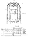
- FIG. 2 shows the sequence of operation for the various camming switches that control the opening and closing of the inlet valves and the purge valves.
- 1TC refers to a first timer cam switch which activates inlet valves 16 and 18.
- 2TC refers to a second timer cam switch which operates purge valve 48 and
- 3TC refers to a third timer cam switch which operates purge valve 50.
- 4TC refers to a fourth timer cam switch which activate repressurization valve 56.
- the shaded areas in Figure 2 designate a closed switch contact while the open areas designate an open switch contact.
- first timer cam switch In operation, with tower 12 in a drying phase, first timer cam switch, "1TC”, opens valve 16 and closes valve 18 so that saturated air entering the system through inlet 20 passes through valve 16 and into the bottom of tower 12. It should be noted that when valve 16 has been opened by the first timer cam switch purge valve 48 has been closed by the second timer cam switch, "2TC". Thus, all of the air passing through valve 16 is forced into the bottom of tower 12.
- the air entering inlet 20 is at a pressure of approximately 8,0 bar (100 psig) and at a temperature of approximately 38°C (100° Farenheit).
- the desiccant As the air passes upwardly through tower 12 the desiccant adsorbs the moisture from the saturated air and introduces pressurized dry air into conduit 24 with the dry air having a dew point of approximately -40°C (-40° Farenheit).
- the pressurized dry air in conduit 24 will unseat check valve 26 and act on check valve 40 via conduit 44 to keep it in a closed position.
- a portion of the dry air is diverted into conduit 34 and passes through union 38 to unseat check valve 42.
- the dry air then passes through conduit 46 and conduit 30 to be passed downwardly through tower 14.
- the third timer cam switch "3TC" alternately opens and closes so that purge valve 50 is pulsed i.e., alternately opened and closed.
- purge valve 50 would be left open throughout the regenerating cycle. Thus, all of the air diverted into the tower being regenerated was constantly exhausted to the atmosphere.
- tower 14 is alternately pressurized and depressurized thus allowing the dry air passing through it to absorb moisture more quickly with less purge flow.
- the pulsed flow caused by opening and closing purge valve 50 also reduces the amount of dry air released to atmosphere and thus greatly reduces the amount of dry air needed to regenerate the desiccant in the tower. While prior regeneration methods utilized up to 15% of the dry air generated by the drying tower, the present system utilizes approximately 6% of the dry air generated by the drying tower.
- a fourth timer cam switch activates valve 56 to allow a portion of the dry air which would normally exit outlet 28 to flow into the tower which is changing from a regeneration cycle to a drying cycle. While this is happening, the corresponding purge valve for that tower is closed so that the tower is pressurized. This occurs immediately prior to the opening of the corresponding inlet valve for that tower and insures that the tower will be at approximately the same pressure as the saturated air entering the bottom of the tower so that the desiccant is not disturbed by a sudden rush of moisture laden air.
Description
- This invention relates to a gas drying method according to the preamble of
claim 1. - The presence of moisture in gases leads to difficulties in many industries and operations. With a slight drop in temperature, condensation can occur in pipelines and reservoirs which can lead to corrosion, scales, freeze-ups, dirt, etc. which may damage instruments and controls and cause blockages in airlines, produce excessive pressure drops, increase down-time and reduce the life of tools. Similarly in chemical, food and metal working industries, the presence of moisture in the air and gases produces undesired oxidation. It has also been found that the robotics field requires extremely dry air for the operation of its pneumatic systems.
- In order to produce extremely dry air i.e. dew points of minus 40 °C or lower, it is necessary to use an adsorptive drying system. Typically, adsorption drying is done by means of twin towers filled with a desiccant, as for example described in the CH-A-546 092 or US-A-4,306,889. The basis for the conventional twin tower adsorption method is that while one tower is receiving moisture laden air for drying, the other tower is having its desiccant regenerated by passing dry air through that tower. In the past, this regeneration process has been accomplished by taking a portion of the dry air exiting the tower in the drying cycle and passing this air through the other tower to take away moisture from the desiccant in that tower and thus regenerate that desiccant. The US-A-4,306,889 describes a device that senses the flow of air through the dryer. If the flow is slow due to low consumption, the system reduces the purge flow. The system according to the CH-A-546,092 also senses the flow into a cable by monitoring pressure. The system will stop the air flow and purge flow at certain pressures. As the pressure in the system drops, the flow and purge valves are opened. As with the US-A-4,306,889, the system requires the monitoring of a condition, i.e. system pressure, and varies the purge flow in response to this monitored condition. According to practical experience with the prior known systems, typically 15% of the dry air exiting the tower in the drying cycle is utilized to regenerate the other tower. This method has the obvious disadvantage of diverting 15% of the dry air away from its end use in order to utilize it for regenerating one of the towers. Therefore, it is desirable to have a system that could reduce the amount of dry air needed to regenerate the towers to an amount that is considerably less than 15%.
- The gas drying method were further developed according to the characterizing part of
claim 1, and provide a process for limiting the amount of air needed for regeneration of the towers thus allowing a greater percentage of the air exiting the drying tower to be utilized in plant operations. - The drawings illustrate the best mode presently contemplated of carrying out the invention.
- In the drawings:
- FIGURE 1 is a front elevational view of a gas drying apparatus constructed according to the invention;
- FIGURE 2 is a chart showing the sequence of operation for the cam switches that operate the various valves of the apparatus in Figure 1; and
- FIGURE 3 is a plan view of the apparatus in Figure 1.
- As shown in Figure 1,
gas drying apparatus 10 includes a pair oftowers - Each of the towers is provided with an inlet halve 16 and 18, respectively, which when open allows saturated air entering the system through
inlet 20 to pass upwardly through the tower and the desiccant therein thus allowing the desiccant to adsorb the moisture from the air. - The opening and closing of
valves control box 22. As the cams rotate into and out of position switches are opened and closed causing solenoids to open and close the various valves in the system. The timing of the cam operated valves and their opening and closing is shown in Figure 2 and will be described in detail below. This valve sequencing can also be accomplished with an electronic or pneumatic timing device rather than the mechanical device described herein. - As dry air exits the upper portion of
tower 12 it passes throughconduit 24 and unseats oneway check valve 26 so that the dry air may pass to and throughoutlet 28. Similarly whentower 14 is in the drying cycle, dry air exits the top oftower 14 throughconduit 30, unseats oneway check valve 32 andexits outlet 28. - A portion of the dry air that arrives at
outlet 28 is diverted throughconduit 34 by means of a purge adjusting valve (not shown). The amount of dry air passing throughconduit 34 is monitored bymeter 36 and the purge valve is adjusted so that the desired amount of dry air is diverted. Once diverted intoconduit 34 the dry air passes through an orifice inunion 38 and from there through eitherregeneration valve 40 or 42.Regeneration valves 40 and 42 are one way check valves that only allow flow in a direction fromunion 38 towardconduits tower 12 is in a drying cycle and is providing pressurized dry air to conduit 24, this pressure will be realized inconduit 44 and one way check valve will be forced into a seated position and will not allow flow fromconduit 44 towardsunion 38. On the other hand,tower 14 will be in a regenerating cycle sincetower 12 is in a drying cycle. Thus, one way check valve 42 will not experience any biasing pressure fromconduit 46 and the pressure of the dry air inconduit 34 andunion 38 will unseat regeneration valve 42 and allow dry air to pass fromunion 38 intoconduit 46. Since the pressure on the left side ofcheck valve 32 is greater than that on the right side, the dry air inconduit 46 will pass throughconduit 30 and downwardly throughtower 14 thus regenerating the desiccant intower 14. Each of the towers is also provided with apurge valve muffled openings -
Gas drying apparatus 10 is also provided with arepressurization valve 56 which when open will provide pressurized dry air tounion 38 viaconduit 58 and from there to one of the towers at the end of its regenerating cycle. Thepressurization valve 56 is opened to provide pressurized air to a tower prior to its entering a drying cycle so that the introduction of pressurized saturated air into the bottom of the tank at the beginning of its drying cycle does not disturb the desiccant in the drying tower. - In describing the operation of
gas drying apparatus 10 we will assume thattower 12 is initially in a drying phase and thattower 14 is initially in a regenerating phase. Reference will also be made to Figure 2 which shows the sequence of operation for the various camming switches that control the opening and closing of the inlet valves and the purge valves. In Figure 2 "1TC" refers to a first timer cam switch which activatesinlet valves purge valve 48 and "3TC" refers to a third timer cam switch which operatespurge valve 50. "4TC" refers to a fourth timer cam switch which activaterepressurization valve 56. The shaded areas in Figure 2 designate a closed switch contact while the open areas designate an open switch contact. - The typical cycle for drying and regeneration is ten minutes and thus the 50% line in Figure 2 would represent the five minute mark in the total cycle. At the five minute mark the process reverses i.e.,
tower 12 which was in a drying phase now goes to a regenerating phase andtower 14 which was in a regenerating phase goes to a drying phase. - In operation, with
tower 12 in a drying phase, first timer cam switch, "1TC", opensvalve 16 and closesvalve 18 so that saturated air entering the system throughinlet 20 passes throughvalve 16 and into the bottom oftower 12. It should be noted that whenvalve 16 has been opened by the first timer camswitch purge valve 48 has been closed by the second timer cam switch, "2TC". Thus, all of the air passing throughvalve 16 is forced into the bottom oftower 12. Theair entering inlet 20 is at a pressure of approximately 8,0 bar (100 psig) and at a temperature of approximately 38°C (100° Farenheit). As the air passes upwardly throughtower 12 the desiccant adsorbs the moisture from the saturated air and introduces pressurized dry air intoconduit 24 with the dry air having a dew point of approximately -40°C (-40° Farenheit). - The pressurized dry air in
conduit 24 willunseat check valve 26 and act oncheck valve 40 viaconduit 44 to keep it in a closed position. As the air passes throughoutlet 28, a portion of the dry air is diverted intoconduit 34 and passes throughunion 38 to unseat check valve 42. The dry air then passes throughconduit 46 andconduit 30 to be passed downwardly throughtower 14. During this regeneration cycle the third timer cam switch "3TC" alternately opens and closes so thatpurge valve 50 is pulsed i.e., alternately opened and closed. In prior art dryingsystems purge valve 50 would be left open throughout the regenerating cycle. Thus, all of the air diverted into the tower being regenerated was constantly exhausted to the atmosphere. - By alternately opening and closing
purge valve 50tower 14 is alternately pressurized and depressurized thus allowing the dry air passing through it to absorb moisture more quickly with less purge flow. The pulsed flow caused by opening and closingpurge valve 50 also reduces the amount of dry air released to atmosphere and thus greatly reduces the amount of dry air needed to regenerate the desiccant in the tower. While prior regeneration methods utilized up to 15% of the dry air generated by the drying tower, the present system utilizes approximately 6% of the dry air generated by the drying tower. - As shown in Figure 2, immediately prior to each tower changing from a regeneration cycle to a drying cycle, a fourth timer cam switch activates
valve 56 to allow a portion of the dry air which would normally exitoutlet 28 to flow into the tower which is changing from a regeneration cycle to a drying cycle. While this is happening, the corresponding purge valve for that tower is closed so that the tower is pressurized. This occurs immediately prior to the opening of the corresponding inlet valve for that tower and insures that the tower will be at approximately the same pressure as the saturated air entering the bottom of the tower so that the desiccant is not disturbed by a sudden rush of moisture laden air. - While the above description has been limited to a heatless type twin tower gas dryer, the inventors contemplate that a similar apparatus could be used in a heat type gas dryer.
Claims (4)
- A method of drying gas in an apparatus having at least two desiccant containing towers (12, 14) which alternately receive moisture saturated air to be dried during a drying phase and then receive dry air during a regenerating phase to regenerate the desiccant which had previously adsorbed moisture from saturated air during the drying phase, said method comprising:- introducing saturated air into one (e.g. 12) of the towers during its drying phase and passing the saturated air over the desiccant so that dry air exits the tower, and- introducing a portion of said dry air from said one tower (e.g. 12) into the other (e.g. 14) of said towers during the regenerating phase of said other tower and passing said dry air over the desiccant which had previously adsorbed moisture during its drying phase so that said dry air takes away moisture from the desiccant and regenerates the desiccant, said method further characterized by- alternately pressurizing and depressurizing said other tower (e.g. 14) in its regenerating phase so that the air in said other tower is periodically allowed to expand.
- The method of claim 1 wherein said gas drying apparatus (10) includes a purge valve (48, 50) for releasing the air used during regeneration and said pressurizing and depressurizing comprises alternately opening and closing the purge valve (e.g. 50) which releases the air from said other tower (e.g. 14).
- The method of claim 2 further comprising using less than ten percent (10 %) of the total dry air generated by said one tower (e.g. 12) for introduction into said other tower (e.g. 14).
- The method of one or more of the claims 1 to 3, further diverting a portion of the dry air exiting a first tower (e.g. 12) under pressure at the end of its drying cycle and directing said portion of the dry air to a second tower (e.g. 14) completing its regenerating cycle and having its associated purge valve (e.g. 50) closed so that said second tower (e.g. 14) is pressurized prior to entering its drying cycle.
Priority Applications (2)
| Application Number | Priority Date | Filing Date | Title |
|---|---|---|---|
| US07/057,700 US4738692A (en) | 1986-02-14 | 1987-05-26 | Gas drying apparatus |
| EP19880104106 EP0332724B1 (en) | 1988-03-15 | 1988-03-15 | Gas drying method |
Applications Claiming Priority (1)
| Application Number | Priority Date | Filing Date | Title |
|---|---|---|---|
| EP19880104106 EP0332724B1 (en) | 1988-03-15 | 1988-03-15 | Gas drying method |
Publications (2)
| Publication Number | Publication Date |
|---|---|
| EP0332724A1 EP0332724A1 (en) | 1989-09-20 |
| EP0332724B1 true EP0332724B1 (en) | 1993-01-13 |
Family
ID=8198810
Family Applications (1)
| Application Number | Title | Priority Date | Filing Date |
|---|---|---|---|
| EP19880104106 Expired - Lifetime EP0332724B1 (en) | 1986-02-14 | 1988-03-15 | Gas drying method |
Country Status (1)
| Country | Link |
|---|---|
| EP (1) | EP0332724B1 (en) |
Families Citing this family (5)
| Publication number | Priority date | Publication date | Assignee | Title |
|---|---|---|---|---|
| US5926969A (en) * | 1997-06-13 | 1999-07-27 | Universal Dynamics, Inc. | Method and apparatus for regenerating a moist absorption medium |
| GB9723033D0 (en) | 1997-11-01 | 1998-01-07 | Domnick Hunter Ltd | Selective absorption of components of a gas mixture |
| CN102271603A (en) | 2008-11-17 | 2011-12-07 | 明诺医学股份有限公司 | Selective accumulation of energy with or without knowledge of tissue topography |
| CZ305090B6 (en) * | 2011-12-09 | 2015-04-29 | ATMOS Chrást s.r.o. | Gas drying apparatus |
| DE202016106099U1 (en) * | 2016-10-31 | 2016-11-22 | Hanno Lenke | Adsorption dryers for gases for industry |
Family Cites Families (3)
| Publication number | Priority date | Publication date | Assignee | Title |
|---|---|---|---|---|
| CH546092A (en) * | 1972-02-03 | 1974-02-28 | Posta Kiserleti Intezet | EQUIPMENT FOR THE GENERATION OF DRY COMPRESSED AIR E.g. FOR THE INSULATION OF CABLES USING COMPRESSED AIR. |
| US4306889A (en) * | 1980-07-28 | 1981-12-22 | Pintsch Bamag Gastechnik Gmbh | Adsorber device for gas drying and desiccant regeneration |
| DE3310842A1 (en) * | 1983-03-25 | 1984-10-04 | Zander Aufbereitungstechnik GmbH, 4300 Essen | ADSORPTION DRYER |
-
1988
- 1988-03-15 EP EP19880104106 patent/EP0332724B1/en not_active Expired - Lifetime
Also Published As
| Publication number | Publication date |
|---|---|
| EP0332724A1 (en) | 1989-09-20 |
Similar Documents
| Publication | Publication Date | Title |
|---|---|---|
| US4738692A (en) | Gas drying apparatus | |
| US7000332B1 (en) | Pulse purge regenerative gas dryer | |
| EP1378286B1 (en) | Adsorption gas dryer | |
| JP2674717B2 (en) | Gas supply device and gas dehumidification method | |
| TWI511773B (en) | Purification of air | |
| US4631073A (en) | Method and apparatus for theadsorptive fractionation of gases | |
| US3719025A (en) | Resolving gas mixtures | |
| KR100346487B1 (en) | Pressure swing adsorption gas flow control method and system | |
| EP0003022B1 (en) | Multi-chamber adsorbent gas fractionator with non-jamming shuttle valve | |
| CA1332047C (en) | Gas drying or fractioning apparatus and method | |
| US6037169A (en) | Garbage disposal apparatus | |
| EP0009139B1 (en) | Heatless adsorbent fractionators with microprocessor cycle control and process | |
| US3513631A (en) | Heat-reactivatable adsorbent gas fractionator and process | |
| EP0168336B1 (en) | Twin tower gas fractionation apparatus | |
| AU749819B2 (en) | Membrane air dryer with scheme to reduce air lost as sweep air | |
| US4054428A (en) | Method and apparatus for removing carbon monoxide from compressed air | |
| EP0332724B1 (en) | Gas drying method | |
| CA1277925C (en) | Gas drying apparatus | |
| NL8720055A (en) | METHOD AND APPARATUS FOR CONCENTRATING GASES | |
| AU629740B2 (en) | Economical air separator | |
| JPH07222909A (en) | Pressure swing adsorber - valve operation | |
| KR950006514B1 (en) | Gas drying apparatus | |
| WO1985001058A1 (en) | Process and apparatus associated with gas purification | |
| JP4351174B2 (en) | Method for continuous supply in dehumidification of compressed gas and dehumidifier for compressed gas | |
| DK170395B1 (en) | Method of drying gas |
Legal Events
| Date | Code | Title | Description |
|---|---|---|---|
| PUAI | Public reference made under article 153(3) epc to a published international application that has entered the european phase |
Free format text: ORIGINAL CODE: 0009012 |
|
| AK | Designated contracting states |
Kind code of ref document: A1 Designated state(s): BE FR GB IT NL SE |
|
| 17P | Request for examination filed |
Effective date: 19900216 |
|
| 17Q | First examination report despatched |
Effective date: 19910214 |
|
| RTI1 | Title (correction) | ||
| RAP1 | Party data changed (applicant data changed or rights of an application transferred) |
Owner name: PNEUMATECH, INC. |
|
| GRAA | (expected) grant |
Free format text: ORIGINAL CODE: 0009210 |
|
| ITF | It: translation for a ep patent filed |
Owner name: STUDIO MASSARI S.R.L. |
|
| AK | Designated contracting states |
Kind code of ref document: B1 Designated state(s): BE FR GB IT NL SE |
|
| PG25 | Lapsed in a contracting state [announced via postgrant information from national office to epo] |
Ref country code: SE Effective date: 19930113 Ref country code: BE Effective date: 19930113 Ref country code: NL Effective date: 19930113 |
|
| ITTA | It: last paid annual fee | ||
| ET | Fr: translation filed | ||
| NLV1 | Nl: lapsed or annulled due to failure to fulfill the requirements of art. 29p and 29m of the patents act | ||
| PLBE | No opposition filed within time limit |
Free format text: ORIGINAL CODE: 0009261 |
|
| STAA | Information on the status of an ep patent application or granted ep patent |
Free format text: STATUS: NO OPPOSITION FILED WITHIN TIME LIMIT |
|
| 26N | No opposition filed | ||
| PGFP | Annual fee paid to national office [announced via postgrant information from national office to epo] |
Ref country code: FR Payment date: 19980209 Year of fee payment: 11 |
|
| PGFP | Annual fee paid to national office [announced via postgrant information from national office to epo] |
Ref country code: GB Payment date: 19980220 Year of fee payment: 11 |
|
| PG25 | Lapsed in a contracting state [announced via postgrant information from national office to epo] |
Ref country code: GB Free format text: LAPSE BECAUSE OF NON-PAYMENT OF DUE FEES Effective date: 19990315 |
|
| GBPC | Gb: european patent ceased through non-payment of renewal fee |
Effective date: 19990315 |
|
| PG25 | Lapsed in a contracting state [announced via postgrant information from national office to epo] |
Ref country code: FR Free format text: LAPSE BECAUSE OF NON-PAYMENT OF DUE FEES Effective date: 19991130 |
|
| REG | Reference to a national code |
Ref country code: FR Ref legal event code: ST |
|
| PG25 | Lapsed in a contracting state [announced via postgrant information from national office to epo] |
Ref country code: IT Free format text: LAPSE BECAUSE OF NON-PAYMENT OF DUE FEES Effective date: 20050315 |