EP0331925B1 - Branching filter - Google Patents
Branching filter Download PDFInfo
- Publication number
- EP0331925B1 EP0331925B1 EP89102292A EP89102292A EP0331925B1 EP 0331925 B1 EP0331925 B1 EP 0331925B1 EP 89102292 A EP89102292 A EP 89102292A EP 89102292 A EP89102292 A EP 89102292A EP 0331925 B1 EP0331925 B1 EP 0331925B1
- Authority
- EP
- European Patent Office
- Prior art keywords
- branch
- frequency range
- point
- inductance
- way
- Prior art date
- Legal status (The legal status is an assumption and is not a legal conclusion. Google has not performed a legal analysis and makes no representation as to the accuracy of the status listed.)
- Expired - Lifetime
Links
Images
Classifications
-
- H—ELECTRICITY
- H03—ELECTRONIC CIRCUITRY
- H03H—IMPEDANCE NETWORKS, e.g. RESONANT CIRCUITS; RESONATORS
- H03H7/00—Multiple-port networks comprising only passive electrical elements as network components
- H03H7/46—Networks for connecting several sources or loads, working on different frequencies or frequency bands, to a common load or source
- H03H7/461—Networks for connecting several sources or loads, working on different frequencies or frequency bands, to a common load or source particularly adapted for use in common antenna systems
Definitions
- the invention relates to a crossover network according to the preamble of claim 1.
- a crossover network is known, for example, from the "Wak 202" device of the applicant, the basic circuit of which is shown in FIG.
- the remote feed current is delivered or required in the further cable run of the high-pass branch.
- the longitudinal element of the high-pass branch is bridged by a choke D and a separating capacitance C is provided in the longitudinal branch of the low-pass filter.
- This known crossover which can be made suitable for remote feed with little effort, works satisfactorily in the VHF range.
- the invention is therefore based on the object of a crossover To further develop in accordance with the preamble of claim 1 that the remote feed means cause only a minimal deterioration in the high-frequency transmission properties of the crossover in a simple and inexpensive manner even at high frequencies and supply currents.
- the remote supply voltage is applied directly to the branch connection, so that the decoupling between the connections of the two branches is not optimal for a higher and a lower frequency range, but is lower compared to an otherwise identical crossover network without remote supply.
- This deterioration in the coupling attenuation between the connections mentioned can be avoided in a simple manner by providing at least two longitudinal coils in the branch for the lower frequency range and, according to claim 3, the remote feed connection having as many longitudinal inductances as possible with the disconnection or interconnection point of the crossover on the one hand and the connection point of this branch is connected on the other hand. With an even number of coils, this division can be implemented exactly. In the case of an odd number of series inductors, however, this only applies if the center coil can be tapped; otherwise it is usually cheaper to provide the remote feed connection between the middle coil and the coil following next to the branch connection point.
- the disruptive influence of the stray capacitance of the choke on the transmission properties in the lower frequency range, in particular their return loss, is noticeably reduced. If the capacitance is not only used as a block capacitor, but also by appropriate dimensioning together with the stray capacitance of the choke to increase the filter edges in the lower frequency range, multiple use of this component is achieved with the least possible effort.
- An embodiment of the remote feed choke according to claim 5 means a slightly higher production cost, but the winding capacity is lower than with a single large choke and thus, as desired, the influence reducing the decoupling of the two branch connections is significantly reduced.
- the smaller partial chokes noticeably reduce the quality of a series resonant circuit which is switched on for the flank distribution as a cross member in the branch for the higher frequency range.
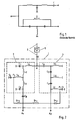
- FIG. 1 shows a remote feed switch according to the prior art.
- FIG. 2 shows a circuit diagram of an exemplary embodiment of the crossover according to the invention in an application as an antenna outlet for use in a communal installation for the transmission of terrestrial and satellite radio signals.
- the crossover 1 of the antenna end socket is connected to this at the receiver end of a trunk line 2 at the separation point A and consists of a low pass 3 for the frequency range up to 860 MHz (terrestrial television), which is continued at connection A 1 to a television set, and a high pass 4 for the frequency range from 950 MHz (first satellite intermediate frequency range), which is continued at connection A2 (originally right-hand circularly polarized satellite signals) to a satellite tuner connected to the television.
- the low-pass filter 3 consists of three longitudinal inductors L1, L2, L3 and, accordingly, three transverse capacitances C1, C2, C3 connected to ground.
- the middle cross member contains to increase the filter edge at the upper end of the UHF range between the capacitance C2 and the connection point of the inductors L2 and L3 switched on inductor L4.
- the high-pass filter 4 consists, analogously to the low-pass filter 3, of three longitudinal capacitors C4, C5, C6 and three transverse inductors L5, L6, L7.
- the directly connected to the connection A2 cross inductance L7 is by a capacitance C7 connected to ground to a series resonant circuit for steepening the filter edge at the lower end of the first satellite intermediate frequency range.
- the interconnection point P1 of the transverse inductance L7 and the capacitance C7 of the high-pass filter 4 is connected via a choke Dr2 with a smaller inductance, a choke Dr1 with a larger inductance and a further choke Dr2 with the cross-inductance L4 and the capacitance C2 of the low-pass filter 3 connecting the switching point P2.
- a remote supply direct current supplied from the satellite tuner is via the socket connection A2 for the originally right circularly polarized satellite signals, the transverse inductance L7, the chokes Dr2, Dr1 and again Dr2 and the inductors Lmaschineen, L2, L1, the RF input E of the crossover 1 and the main line 2 fed to an amplifier 5 for its operating power supply.
- C7 by appropriate dimensioning simultaneously blocks the DC supply and, together with the stray capacitance, in particular the choke Dr2 connected to the interconnection point P1 and the inductance L7, the already mentioned edge distribution of the high-pass filter 4. Accordingly, C2 acts on the one hand as a block capacitor and, on the other hand, results in particular together with the stray capacitance the choke Dr2 connected to the switching point P2 and the inductance L4 the desired edge distribution at the low-pass filter 3.
- C1 is also effective as a block capacitor, C4 prevents a short-circuit of the remote supply direct current via L5 and C8 its drainage through the connection A1.
- the switching of the crossover according to the invention can be done in be carried out in the same way, except that the inductance of the two partial chokes Dr2 is different and the smaller one is to be connected to the interconnection point P1.
Landscapes
- Filters And Equalizers (AREA)
- Surgical Instruments (AREA)
- Dry Shavers And Clippers (AREA)
- Piezo-Electric Or Mechanical Vibrators, Or Delay Or Filter Circuits (AREA)
- Medicines That Contain Protein Lipid Enzymes And Other Medicines (AREA)
- Networks Using Active Elements (AREA)
- Oscillators With Electromechanical Resonators (AREA)
- Luminescent Compositions (AREA)
- Superconductors And Manufacturing Methods Therefor (AREA)
- Display Devices Of Pinball Game Machines (AREA)
- Transplanting Machines (AREA)
- Control Of Motors That Do Not Use Commutators (AREA)
- Input Circuits Of Receivers And Coupling Of Receivers And Audio Equipment (AREA)
Abstract
Description
Die Erfindung betrifft eine Frequenzweiche gemäß dem Oberbegriff des Anspruches 1. Eine derartige Frequenzweiche ist z.B. durch das Gerät "Wak 202" der Anmelderin bekannt, deren Prinzipschaltung in Figur 1 dargestellt ist. Bei solchen Hoch-/Tiefpaß-Weichen wäre an sich die Fernspeisung über den Tiefpaß-Zweig ohne zusätzliche Schaltmittel möglich. In manchen Fällen wird jedoch der Fernspeisestrom im weiteren Leitungszug des Hochpaß-Zweiges angeliefert bzw. benötigt. Zu diesem Zweck ist dann gemäß Figur 1 das Längsglied des Hochpaß-Zweiges durch eine Drossel D überbrückt und im Längszweig des Tiefpasses eine Trennkapazität C vorgesehen.
Diese mit geringem Aufwand fernspeisetauglich gemachte bekannte Frequenzweiche funktioniert im VHF-Bereich zufriedenstellend. Bei hohen Frequenzen ab dem UHF-Bereich wirken sich jedoch die Windungs- und Streukapazitäten der Drossel nachteilig auf die Übertragungseigenschaften des Hochpaß-Zweiges aus: Die Durchgangsdämpfung wird größer, die Rückflußdämpfung und die Koppeldämpfung geringer, die Sperrwirkung in diesem Zweig für die Frequenzen des über den Tiefpaß-Zweig übertragenen Bereichs verschlechert.
Diese Nachteile werden mit höheren Speiseströmen (und damit größerem Drahtdurchmesser der Drossel) und/oder wachsenden Frequenzen gravierender. Bei dem mit wachsender Anzahl von Satelliten-Empfangsanlagen immer häufiger werdenden Einsatz von Weichen im ersten Satelliten-Zwischenfrequenzbereich, über die z.B. aus dem beim Fernsehempfänger angeordneten Satellitentuner Verstärker fernzuspeisen sind, ist die bekannte Schaltung aus dem genannten Grund meist nicht mehr brauchbar.The invention relates to a crossover network according to the preamble of
This known crossover, which can be made suitable for remote feed with little effort, works satisfactorily in the VHF range. At high frequencies from the UHF range, however, the winding and stray capacities of the choke adversely affect the transmission properties of the high-pass branch: the transmission loss is greater, the return loss and the coupling loss is lower, the blocking effect in this branch for the frequencies of the over the low pass branch transmitted area deteriorated.
These disadvantages become more serious with higher feed currents (and thus larger wire diameter of the choke) and / or increasing frequencies. With the increasing use of switches in the first satellite intermediate frequency range, with which, for example, amplifiers can be remotely fed from the satellite tuner arranged at the television receiver, the known circuit is usually no longer usable for the reason mentioned.
Der Erfindung liegt daher die Aufgabe zugrunde, eine Frequenzweiche gemäß dem Oberbegriff des Anspruches 1 derart weiterzubilden, daß auf einfache und kostengünstige Weise auch bei hohen Frequenzen und Speiseströmen die Fernspeisemittel nur eine möglichst geringe Verschlechterung der Hochfrequenz-Übertragungseigenschaften der Frequenzweiche verursachen.The invention is therefore based on the object of a crossover To further develop in accordance with the preamble of
Diese Aufgabe ist durch die Merkmale des Anspruches 1 gelöst.
Durch die Führung des Fernspeisestroms von einem "hochfrequenzmäßig kalten" Schaltungspunkt des Zweiges für eine höhere Frequenz über die Drossel und wenigstens eine Induktivität des Zweiges für eine tiefere Frequenz ist die Beeinflussung der Hochfrequenzkreise der Frequenzweiche gegenüber dem Stand der Technik entscheidend verringert. Dadurch werden ihre Hochfrequenz-Übertragungseigenschaften selbst bei den hohen Frequenzen des ersten Satelliten-Zwischenfrequenzbereiches und bei hohen Speiseströmen nur unwesentlich verschlechtert.
Dabei ist mit dem Blockkondensator lediglich ein einziges zusätzliches Bauteil und somit ein äußerst geringer Mehraufwand erforderlich.
Wenn die Frequenzweiche mehrere Zweige für die Übertragung unterschiedlicher Frequenzbereiche aufweist, so ist die maximale Wirkung der erfindungsgemäßen Maßnahme dann erreicht, wenn der Zweig für den höchsten Frequenzbereich mit demjenigen für den tiefsten Frequenzbereich auf die im Anspruch 1 angegebene Weise zusammengeschaltet werden.This object is solved by the features of
By influencing the remote supply current from a "high-frequency cold" switching point of the branch for a higher frequency via the choke and at least one inductance of the branch for a lower frequency, the influence of the high-frequency circuits of the crossover network is significantly reduced compared to the prior art. As a result, their high-frequency transmission properties are only insignificantly deteriorated even at the high frequencies of the first satellite intermediate frequency range and at high feed currents.
In this case, the block capacitor only requires a single additional component and therefore extremely little additional effort.
If the crossover has several branches for the transmission of different frequency ranges, then the maximum effect of the measure according to the invention is achieved if the branch for the highest frequency range is interconnected with that for the lowest frequency range in the manner specified in
In den Unteransprüchen sind vorteilhafte Weiterbildungen der erfindungsgemäßen Frequenzweiche beschrieben.
So ist durch eine Ausgestaltung nach Anspruch 2 auf einfache Weise eine Doppelnutzung des Blockkondensators erreicht. Dies ist selbstverständlich auch dann der Fall, wenn - wie es in der Praxis häufig vorkommt-der Querinduktivität zur Flankenversteilerung der Übertragungskennlinie bereits ein Kondensator in Serie geschaltet ist. Dann kann dieser zugleich als Blockkondensator zur Vermeidung eines Kurzschlusses für den Speisestrom mitbenutzt werden, so daß der erfindungsgemäße Vorteil ohne jeglichen Mehraufwand erreicht ist.Advantageous developments of the crossover according to the invention are described in the subclaims.
Thus, a double use of the block capacitor is achieved in a simple manner by an embodiment according to
Ist im niederfrequenten Zweig nur eine einzige Längsinduktivität vorgesehen, so liegt die Fernspeisespannung direkt am Zweiganschluß an, so daß die Entkopplung zwischen den Anschlüssen der beiden Zweige für einen höheren und einen tieferen Frequenzbereich nicht optimal, sondern gegenüber einer ansonsten gleichen Frequenzweiche ohne Fernspeisung geringer ist. Diese Verschlechterung der Koppeldämpfung zwischen den genannten Anschlüssen läßt sich auf einfache Weise dadurch vermeiden, daß im Zweig für den tieferen Frequenzbereich mindestens zwei Längsspulen vorgesehen sind und gemäß Anspruch 3 der Fernspeiseanschluß über möglichst gleich viele Längsinduktivitäten mit dem Auftrenn- bzw. Zusammenschaltpunkt der Frequenzweiche einerseits und dem Anschlußpunkt dieses Zweiges andererseits verbunden ist. Bei geradzahliger Spulenanzahl ist diese Aufteilung exakt realisierbar. Bei ungeradzahliger Anzahl von Längsinduktivitäten gilt dies jedoch nur, wenn eine Mittelanzapfung der mittleren Spule möglich ist; andernfalls ist es zumeist günstiger, den Fernspeiseanschluß zwischen der mittleren und der zum Zweiganschlußpunkt hin nächstfolgenden Spule vorzusehen.If only a single series inductance is provided in the low-frequency branch, then the remote supply voltage is applied directly to the branch connection, so that the decoupling between the connections of the two branches is not optimal for a higher and a lower frequency range, but is lower compared to an otherwise identical crossover network without remote supply. This deterioration in the coupling attenuation between the connections mentioned can be avoided in a simple manner by providing at least two longitudinal coils in the branch for the lower frequency range and, according to
Durch einen Schaltungsaufbau nach Anspruch 4 ist in vorteilhafter Weise der störende Einfluß der Streukapazität der Drossel auf die Übertragungseigenschaften im tieferen Frequenzbereich, insbesondere deren Rückflußdämpfung spürbar vermindert. Wird dabei die Kapazität nicht nur als Blockkondensator, sondern durch entsprechende Bemessung zusammen mit der Streukapazität der Drossel zugleich zur Versteilerung der Filterflanken im tieferen Frequenzbereich benutzt, so ist mit geringstmöglichem Aufwand eine Mehrfachnutzung dieses Bauteils erreicht.By a circuit structure according to
Eine Ausführung der Fernspeise-Drossel gemäß Anspruch 5 bedeutet zwar einen geringfügig höheren Herstellungsaufwand, dafür ist jedoch die Windungskapazität geringer als bei einer einzigen großen Drossel und damit wunschgemäß der die Entkopplung der beiden Zweiganschlüsse mindernde Einfluß wesentlich herabgesetzt. Außerdem ist durch die kleineren Teildrosseln die die Güte eines zur Flankenversteilerung als Querglied im Zweig für den höheren Frequenzbereich eingeschalteten Serienresonanzkreises verschlechternde Wirkung spürbar verringert.An embodiment of the remote feed choke according to
In der Regel stellt eine Aufteilung in drei Teildrosseln mit einer größeren mittleren und zwei kleineren Teildrosseln zu den Zweiganschlüssen hin einen besonders günstigen Kompromiß zwischen Aufwand und elektrischer Wirkung dar. Sofern die Frequenzbereiche der beiden Zweige nicht sehr stark unterschiedlich sind, können im Hinblick auf eine kostengünstige Mengenfertigung die beiden kleineren Teildrosseln gleich ausgeführt werden. Liegen jedoch die Frequenzbereiche der beiden Zweige sehr weit auseinander, so ist es zweckmäßig, diese beiden kleineren Teildrosseln unterschiedlich auszuführen, wobei diejenige mit der geringeren Induktivität zu dem Zweig für den höheren Frequenzbereich hin anzuordnen ist.As a rule, a division into three partial chokes with a larger middle and two smaller partial chokes towards the branch connections represents a particularly favorable compromise between effort and electrical effect. Unless the frequency ranges of the two branches are very different, in view of an economical one Bulk production the two smaller chokes can be carried out in the same way. However, if the frequency ranges of the two branches are very far apart, it is expedient to design these two smaller partial chokes differently, the one with the lower inductance toward the branch being arranged for the higher frequency range.
Die Erfindung wird mittels der Zeichnungen näher beschrieben. In Figur 1 ist eine Fernspeiseweiche nach dem Stand der Technik dargestellt.The invention is described in more detail by means of the drawings. 1 shows a remote feed switch according to the prior art.
In Figur 2 ist ein Schaltbild eines Ausführungsbeispiels der erfindungsgemäßen Frequenzweiche in einer Anwendung als Antennen-Endsteckdose zum Einsatz in einer Gemeinschaftsanlage für die Übertragung terrestrischer und Satelliten-Rundfunksignale dargestellt.FIG. 2 shows a circuit diagram of an exemplary embodiment of the crossover according to the invention in an application as an antenna outlet for use in a communal installation for the transmission of terrestrial and satellite radio signals.
Die Frequenzweiche 1 der Antennen-Endsteckdose ist am empfängerseitigen Ende einer Stammleitung 2 am Auftrennpunkt A an diese angeschlossen und besteht aus einem Tiefpaß 3 für den Frequenzbereich bis 860 MHz (terrestrisches Fernsehen), der am Anschluß A₁ zu einem Fernsehgerät weitergeführt wird, sowie einem Hochpaß 4 für den Frequenzbereich ab 950 MHz (erster Satelliten-Zwischenfrequenzbereich), der am Anschluß A₂ (ursprünglich rechtszirkular polarisierte Satellitensignale) zu einem am Fernsehgerät angeschlossenen Satellitentuner weitergeführt wird. Der Tiefpaß 3 besteht aus drei Längsinduktivitäten L₁, L₂, L₃ und entsprechend drei gegen Masse geschalteten Querkapazitäten C₁, C₂, C₃. Das mittlere Querglied enthält zur Versteilerung der Filterflanke am oberen Ende des UHF-Bereichs eine zwischen der Kapazität C₂ und dem Verbindungspunkt der Induktivitäten L₂ und L₃ eingeschaltete Induktivität L₄. Der Hochpaß 4 besteht analog zum Tiefpaß 3 aus drei Längskapazitäten C₄, C₅, C₆ und drei Querinduktivitäten L₅, L₆, L₇. Die mit dem Anschluß A₂ direkt verbundene Querinduktivität L₇ ist durch eine gegen Masse geschaltete Kapazität C₇ zu einem Reihenresonanzkreis zur Versteilerung der Filterflanke am unteren Ende des ersten Satelliten-Zwischenfrequenzbereichs ergänzt.The
Der Zusammenschaltpunkt P₁ der Querinduktivität L₇ und der Kapazität C₇ des Hochpasses 4 ist über eine Drossel Dr₂ mit kleinerer Induktivität, einer Drossel Dr₁ mit größerer Induktivität und einer weiteren Drossel Dr₂ mit dem die Querinduktivität L₄ und die Kapazität C₂ des Tiefpasses 3 verbindenden Schaltungspunkt P₂ verbunden.
Ein aus dem Satellitentuner gelieferter Fernspeisegleichstrom wird über den Steckdosenanschluß A₂ für die ursprünglich rechtszirkular polarisierten Satellitensignale, die Querinduktivität L₇, die Drosseln Dr₂, Dr₁ und wiederum Dr₂ sowie die Induktivitäten L₄, L₂, L₁, den HF-Eingang E der Frequenzweiche 1 und die Stammleitung 2 einem Verstärker 5 zu dessen Betriebsstromversorgung zugeführt.
C₇ bewirkt durch entsprechende Bemessung zugleich eine Abblockung des Fernspeisegleichstroms sowie zusammen mit der Streukapazität insbesondere der am Zusammenschaltpunkt P₁ angeschlossenen Drossel Dr₂ und der Induktivität L₇ die bereits angeführte Flankenversteilerung des Hochpasses 4. Entsprechend wirkt C₂ einerseits als Blockkondensator und ergibt zum anderen zusammen mit der Streukapazität insbesondere der am Schaltungspunkt P₂ angeschlossenen Drossel Dr₂ und der Induktivität L₄ die angestrebte Flankenversteilerung beim Tiefpaß 3.
C₁ ist ebenfalls als Blockkondensator wirksam, C₄ verhindert einen Kurzschluß des Fernspeisegleichstroms über L₅ und C₈ dessen Abfließen über den Anschluß A₁.The interconnection point P₁ of the transverse inductance L₇ and the capacitance C₇ of the high-
A remote supply direct current supplied from the satellite tuner is via the socket connection A₂ for the originally right circularly polarized satellite signals, the transverse inductance L₇, the chokes Dr₂, Dr₁ and again Dr₂ and the inductors Litäten, L₂, L₁, the RF input E of the
C₇ by appropriate dimensioning simultaneously blocks the DC supply and, together with the stray capacitance, in particular the choke Dr₂ connected to the interconnection point P₁ and the inductance L₇, the already mentioned edge distribution of the high-
C₁ is also effective as a block capacitor, C₄ prevents a short-circuit of the remote supply direct current via L₅ and C₈ its drainage through the connection A₁.
Durch die beschriebene Führung des Fernspeisegleichstroms über die Frequenzweiche ist auf äußerst einfache und kostengünstige Weise erreicht, daß die Hochfrequenz-Übertragungseigenschaften der Frequenzweiche durch den mitübertragenen Fernspeisegleichstrom praktisch nicht merklich verschlechtert sind.By the described guidance of the remote feed direct current over the crossover, it is achieved in an extremely simple and inexpensive manner that the high frequency transmission properties of the crossover are practically not noticeably deteriorated by the remote feed direct current which is also transmitted.
Bei einer analogen Antennen-Endsteckdose zum Empfang ursprünglich linkszirkular polarisierter Satellitensignale sowie des terrestrischen Tonrundfunks kann die Schaltung der erfindungsgemäßen Frequenzweiche in gleicher Weise ausgeführt werden, wobei lediglich die Induktivität der beiden Teildrosseln Dr₂ ungleich zu bemessen und deren kleinere am Zusammenschaltpunkt P₁ anzuschließen ist.In the case of an analog antenna terminal socket for receiving originally left circularly polarized satellite signals and terrestrial audio broadcasting, the switching of the crossover according to the invention can be done in be carried out in the same way, except that the inductance of the two partial chokes Dr₂ is different and the smaller one is to be connected to the interconnection point P₁.
Claims (5)
- Branching filter for dividing a total frequency range into two partial frequency ranges or, respectively, for switching them together, which is used to feed a supply current from a distance into the connection point of a branch for a higher partial frequency range, wherewith this branch possesses at least one capacitor in series and one transverse inductance connected to its connection point,
in such a way characterised, that the transverse inductance (L₇) that is connected to the connection point (A₂) of the branch (4) for a higher partial frequency range is grounded via a block capacitor (C₇) and that the interconnection point (P₁) of these two reactances (L₇, C₇) is connected by way of a choking coil (Dr₁, Dr₂) to a circuit point (P₂) of a branch (3) for a lower partial frequency range that is connected by way of at least one inductance (L₁, L₂, L₄) to the separation point (A) or, respectively, the interconnection point of the frequency branching filter (1). - Branching filter according to claim 1, in such a way characterised, that the block capacitor (C₇) is sized in such a way that in combination with the transverse inductance (L₇) connected in series and the parasitic capacity of the choking coil (Dr₂), it leads to an increase of the flank steepness of the filter characteristics of the branch (4) for a higher partial frequency range.
- Branching filter according to claim 1 or 2 with at least two inductances in series in the one branch (3) for a lower partial frequency range, in such a way characterised, that the circuit point (P₂) is connected by way of an equal number, if possible, of inductances in series (L₁, L₂, L₄ or L₃, L₄, respectively) to the separation point (A) or, respectively, the interconnection point of the frequency branching filter (1) on the one hand and the connection point (A₁) of this branch (3) on the other hand.
- Branching filter according to one of the claims 1 to 3, in such a way characterised, that the branch (3) for a lower partial frequency range possesses at least one transverse element that is designed to act as a resonance circuit in series and whose inductance (L₄) is connected to the element in series and whose capacity (C₂) is connected to ground, and that the interconnection point of these two reactances (L₄, C₂) forms the circuit point (P₂).
- Branching filter according to one of the claims 1 to 4, in such a way characterised, that the choking coil consists of at least two partial choking coils (Dr₁, Dr₂) with different inductances and that the partial choking coil (Dr₂) with the lower inductance is connected to the branch (4) for a higher partial frequency range.
Priority Applications (1)
| Application Number | Priority Date | Filing Date | Title |
|---|---|---|---|
| AT89102292T ATE92222T1 (en) | 1988-03-10 | 1989-02-10 | CROSSOVER. |
Applications Claiming Priority (2)
| Application Number | Priority Date | Filing Date | Title |
|---|---|---|---|
| DE3807912 | 1988-03-10 | ||
| DE3807912A DE3807912C1 (en) | 1988-03-10 | 1988-03-10 |
Publications (3)
| Publication Number | Publication Date |
|---|---|
| EP0331925A2 EP0331925A2 (en) | 1989-09-13 |
| EP0331925A3 EP0331925A3 (en) | 1990-08-22 |
| EP0331925B1 true EP0331925B1 (en) | 1993-07-28 |
Family
ID=6349351
Family Applications (1)
| Application Number | Title | Priority Date | Filing Date |
|---|---|---|---|
| EP89102292A Expired - Lifetime EP0331925B1 (en) | 1988-03-10 | 1989-02-10 | Branching filter |
Country Status (6)
| Country | Link |
|---|---|
| EP (1) | EP0331925B1 (en) |
| AT (1) | ATE92222T1 (en) |
| DE (2) | DE3807912C1 (en) |
| DK (1) | DK109289A (en) |
| ES (1) | ES2042817T3 (en) |
| HU (1) | HU203626B (en) |
Families Citing this family (2)
| Publication number | Priority date | Publication date | Assignee | Title |
|---|---|---|---|---|
| EP0872953A4 (en) * | 1996-09-26 | 2006-06-14 | Matsushita Electric Ind Co Ltd | Branch filter and shared device and 2-frequency band mobile communication apparatus using the branch filter |
| DE19931910C2 (en) * | 1999-07-08 | 2001-10-18 | Kathrein Werke Kg | Remote feed switch |
Family Cites Families (2)
| Publication number | Priority date | Publication date | Assignee | Title |
|---|---|---|---|---|
| US3771064A (en) * | 1972-07-03 | 1973-11-06 | Electronic Labor Inc | Bidirectional signal processing means |
| DE2238716A1 (en) * | 1972-08-05 | 1974-02-07 | Hirschmann Radiotechnik | REMOTE SWITCH |
-
1988
- 1988-03-10 DE DE3807912A patent/DE3807912C1/de not_active Expired
-
1989
- 1989-02-10 AT AT89102292T patent/ATE92222T1/en not_active IP Right Cessation
- 1989-02-10 EP EP89102292A patent/EP0331925B1/en not_active Expired - Lifetime
- 1989-02-10 DE DE8989102292T patent/DE58904997D1/en not_active Expired - Fee Related
- 1989-02-10 ES ES89102292T patent/ES2042817T3/en not_active Expired - Lifetime
- 1989-03-07 DK DK109289A patent/DK109289A/en not_active Application Discontinuation
- 1989-03-08 HU HU891143A patent/HU203626B/en not_active IP Right Cessation
Also Published As
| Publication number | Publication date |
|---|---|
| ES2042817T3 (en) | 1993-12-16 |
| DK109289D0 (en) | 1989-03-07 |
| EP0331925A3 (en) | 1990-08-22 |
| HU203626B (en) | 1991-08-28 |
| ATE92222T1 (en) | 1993-08-15 |
| EP0331925A2 (en) | 1989-09-13 |
| HUT52898A (en) | 1990-08-28 |
| DE3807912C1 (en) | 1989-07-20 |
| DK109289A (en) | 1989-09-11 |
| DE58904997D1 (en) | 1993-09-02 |
Similar Documents
| Publication | Publication Date | Title |
|---|---|---|
| DE69834679T2 (en) | antenna Combiner | |
| DE69730389T2 (en) | LOW PASS FILTER WITH DIRECTED COUPLER AND PORTABLE TELEPHONE THEREOF | |
| DE3638748C2 (en) | ||
| DE3832293C2 (en) | Adjustment circuit | |
| DE10150159A1 (en) | Impedance matching circuit for multiband power amplifier used in wireless communication, has paths with impedance matching network to match impedance of input and output ports for frequency band signals, in desired band | |
| WO2000018026A1 (en) | Multiband antenna switcher | |
| DE102008059157B4 (en) | Differential bandpass filter with symmetrically interwoven inductors | |
| DE3317219A1 (en) | INPUT SWITCHING WITH AT LEAST TWO INPUT WAYS | |
| DE2536496A1 (en) | CIRCUIT ARRANGEMENT FOR SEPARATING TWO SIGNALS OF NEIGHBORING FREQUENCY | |
| EP0091169B1 (en) | Double-tuned resonant bandpass filter for channel selectors | |
| EP0196130B1 (en) | Circuit arrangement for the input stages of a television tuner | |
| EP0331925B1 (en) | Branching filter | |
| DE3111983C2 (en) | Coupling circuit for adapting a loop antenna to a feed cable | |
| EP0151784B1 (en) | High frequency distribution network | |
| EP0044909B1 (en) | High-frequency multiple-distribution circuit arrangement | |
| DE3108993C2 (en) | RF input filter circuit of a tuner | |
| DE3022023C2 (en) | ||
| EP0101789A2 (en) | Filter circuit | |
| DE3538342C2 (en) | ||
| DE2321462C3 (en) | Bandpass filters for radio and television | |
| EP0128532A2 (en) | Tuning circuit for UHF and VHF | |
| DE3416225A1 (en) | SWITCHING A FILTER TUNABLE WITH MICROWAVE FREQUENCIES WITH EXAMPLE OF EMBODIMENT | |
| DE2733316C2 (en) | Electric filter | |
| EP0757412B1 (en) | Antenna plug socket | |
| DE924326C (en) | Adaptation circuit for coupling a consumer to a high-frequency tube transmitter set up for wave change |
Legal Events
| Date | Code | Title | Description |
|---|---|---|---|
| PUAI | Public reference made under article 153(3) epc to a published international application that has entered the european phase |
Free format text: ORIGINAL CODE: 0009012 |
|
| AK | Designated contracting states |
Kind code of ref document: A2 Designated state(s): AT DE ES GR IT SE |
|
| PUAL | Search report despatched |
Free format text: ORIGINAL CODE: 0009013 |
|
| AK | Designated contracting states |
Kind code of ref document: A3 Designated state(s): AT DE ES GR IT SE |
|
| 17P | Request for examination filed |
Effective date: 19900925 |
|
| 17Q | First examination report despatched |
Effective date: 19921211 |
|
| GRAA | (expected) grant |
Free format text: ORIGINAL CODE: 0009210 |
|
| RIN1 | Information on inventor provided before grant (corrected) |
Inventor name: WENDEL, WOLFGANG Inventor name: BLIND, MANFRED |
|
| AK | Designated contracting states |
Kind code of ref document: B1 Designated state(s): AT DE ES GR IT SE |
|
| PG25 | Lapsed in a contracting state [announced via postgrant information from national office to epo] |
Ref country code: GR Free format text: LAPSE BECAUSE OF FAILURE TO SUBMIT A TRANSLATION OF THE DESCRIPTION OR TO PAY THE FEE WITHIN THE PRESCRIBED TIME-LIMIT Effective date: 19930728 |
|
| REF | Corresponds to: |
Ref document number: 92222 Country of ref document: AT Date of ref document: 19930815 Kind code of ref document: T |
|
| REF | Corresponds to: |
Ref document number: 58904997 Country of ref document: DE Date of ref document: 19930902 |
|
| ITF | It: translation for a ep patent filed |
Owner name: DE DOMINICIS & MAYER S. |
|
| REG | Reference to a national code |
Ref country code: ES Ref legal event code: FG2A Ref document number: 2042817 Country of ref document: ES Kind code of ref document: T3 |
|
| PG25 | Lapsed in a contracting state [announced via postgrant information from national office to epo] |
Ref country code: SE Effective date: 19940211 Ref country code: ES Free format text: LAPSE BECAUSE OF NON-PAYMENT OF DUE FEES Effective date: 19940211 |
|
| PLBE | No opposition filed within time limit |
Free format text: ORIGINAL CODE: 0009261 |
|
| STAA | Information on the status of an ep patent application or granted ep patent |
Free format text: STATUS: NO OPPOSITION FILED WITHIN TIME LIMIT |
|
| 26N | No opposition filed | ||
| EUG | Se: european patent has lapsed |
Ref document number: 89102292.3 Effective date: 19940910 |
|
| PGFP | Annual fee paid to national office [announced via postgrant information from national office to epo] |
Ref country code: AT Payment date: 19960227 Year of fee payment: 8 |
|
| PG25 | Lapsed in a contracting state [announced via postgrant information from national office to epo] |
Ref country code: AT Effective date: 19970210 |
|
| PGFP | Annual fee paid to national office [announced via postgrant information from national office to epo] |
Ref country code: DE Payment date: 20020207 Year of fee payment: 14 |
|
| PG25 | Lapsed in a contracting state [announced via postgrant information from national office to epo] |
Ref country code: DE Free format text: LAPSE BECAUSE OF NON-PAYMENT OF DUE FEES Effective date: 20030902 |
|
| REG | Reference to a national code |
Ref country code: ES Ref legal event code: FD2A Effective date: 20031022 |
|
| PG25 | Lapsed in a contracting state [announced via postgrant information from national office to epo] |
Ref country code: IT Free format text: LAPSE BECAUSE OF NON-PAYMENT OF DUE FEES Effective date: 20050210 |