EP0329514A1 - Connecting interface for an information transmission system, e.g. for an automotive vehicle - Google Patents
Connecting interface for an information transmission system, e.g. for an automotive vehicle Download PDFInfo
- Publication number
- EP0329514A1 EP0329514A1 EP89400303A EP89400303A EP0329514A1 EP 0329514 A1 EP0329514 A1 EP 0329514A1 EP 89400303 A EP89400303 A EP 89400303A EP 89400303 A EP89400303 A EP 89400303A EP 0329514 A1 EP0329514 A1 EP 0329514A1
- Authority
- EP
- European Patent Office
- Prior art keywords
- output
- inputs
- flip
- comparator
- flops
- Prior art date
- Legal status (The legal status is an assumption and is not a legal conclusion. Google has not performed a legal analysis and makes no representation as to the accuracy of the status listed.)
- Granted
Links
Images
Classifications
-
- H—ELECTRICITY
- H04—ELECTRIC COMMUNICATION TECHNIQUE
- H04L—TRANSMISSION OF DIGITAL INFORMATION, e.g. TELEGRAPHIC COMMUNICATION
- H04L25/00—Baseband systems
- H04L25/02—Details ; arrangements for supplying electrical power along data transmission lines
- H04L25/08—Modifications for reducing interference; Modifications for reducing effects due to line faults ; Receiver end arrangements for detecting or overcoming line faults
- H04L25/085—Arrangements for reducing interference in line transmission systems, e.g. by differential transmission
-
- B—PERFORMING OPERATIONS; TRANSPORTING
- B60—VEHICLES IN GENERAL
- B60R—VEHICLES, VEHICLE FITTINGS, OR VEHICLE PARTS, NOT OTHERWISE PROVIDED FOR
- B60R16/00—Electric or fluid circuits specially adapted for vehicles and not otherwise provided for; Arrangement of elements of electric or fluid circuits specially adapted for vehicles and not otherwise provided for
- B60R16/02—Electric or fluid circuits specially adapted for vehicles and not otherwise provided for; Arrangement of elements of electric or fluid circuits specially adapted for vehicles and not otherwise provided for electric constitutive elements
- B60R16/03—Electric or fluid circuits specially adapted for vehicles and not otherwise provided for; Arrangement of elements of electric or fluid circuits specially adapted for vehicles and not otherwise provided for electric constitutive elements for supply of electrical power to vehicle subsystems or for
- B60R16/0315—Electric or fluid circuits specially adapted for vehicles and not otherwise provided for; Arrangement of elements of electric or fluid circuits specially adapted for vehicles and not otherwise provided for electric constitutive elements for supply of electrical power to vehicle subsystems or for using multiplexing techniques
Definitions
- the object of the invention is therefore to solve these problems by proposing a connection interface which makes it possible to detect whether one of the two wires of transmission is faulty and which also makes it possible to suppress the capacitive connection of some of the transmission devices currently known and therefore to make their operation with collision buses possible.
Abstract
Cette interface est caractérisée en ce qu'elle comporte trois comparateurs (5,7,8), les entrées du premier comparateur (5) étant raccordées aux deux fils de transmission (2,3), l'une des entrées du second comparateur (7) étant raccordée à l'un (2) des fils de transmission et l'autre entrée de ce comparateur, à un générateur (4) de tension de polarisation, l'une des entrées du troisième comparateur (8) étant reliée à l'autre fil de transmission (3) et l'autre entrée de ce comparateur, au générateur (4) de la tension de polarisation, en ce que les sorties des comparateurs sont reliées à des entrées (A,B,C) d'un multiplexeur (6) dont la sortie (S) est reliée au reste des circuits de la station, et en ce que les entrées de commande (D,E) du multiplexeur (6) sont reliées à la sortie de moyens de détection de défaut (9) de l'un des fils de transmission, de manière que ceux-ci commandent le multiplexeur (6) pour qu'il sélectionne la sortie de l'un des comparateurs en fonction de l'état des fils de transmission.This interface is characterized in that it comprises three comparators (5,7,8), the inputs of the first comparator (5) being connected to the two transmission wires (2,3), one of the inputs of the second comparator ( 7) being connected to one (2) of the transmission wires and the other input of this comparator, to a generator (4) of bias voltage, one of the inputs of the third comparator (8) being connected to the other transmission wire (3) and the other input of this comparator, to the generator (4) of the bias voltage, in that the outputs of the comparators are connected to inputs (A, B, C) of a multiplexer (6) whose output (S) is connected to the rest of the station's circuits, and in that the control inputs (D, E) of the multiplexer (6) are connected to the output of fault detection means ( 9) of one of the transmission wires, so that these control the multiplexer (6) so that it selects the output of one of the comparators according to the state of the fi ls of transmission.
Description
La présente invention concerne les dispositifs de transmission d'informations notamment dans les véhicules automobiles et elle se rapporte plus particulièrement à une interface de raccordement d'une partie de réception d'informations d'une station dans un système de transmission d'informations en différentiel, par deux fils de transmission.The present invention relates to information transmission devices in particular in motor vehicles and it relates more particularly to an interface for connecting an information reception part of a station in a differential information transmission system , by two transmission wires.
On connait déjà dans l'état de la technique, un certain nombre de systèmes de multiplexage qui permettent de relier les fonctions dites "organes de carrosserie" à une unité centrale du véhicule automobile, qui en gère le fonctionnement.There are already known in the prior art, a number of multiplexing systems which make it possible to connect the so-called "bodywork" functions to a central unit of the motor vehicle, which manages its operation.
Ces organes sont reliés entre eux par deux fils de transmission d'informations qui constituent ainsi un bus de liaison.These organs are linked together by two information transmission wires which thus constitute a link bus.
Pour des raisons de sécurité, il est prévu que les systèmes actuels puissent fonctionner en mode dégradé, c'est à dire que le système peut fonctionner même si l'un des deux fils de transmission d'informations est relié à la masse, au potentiel de la batterie ou tout simplement coupé.For security reasons, it is expected that current systems can operate in degraded mode, that is to say that the system can operate even if one of the two information transmission wires is connected to ground, to potential from the battery or just cut off.
Cependant, ce type de dispositifs présente un certain nombre d'inconvénients dans la mesure où lorsqu'ils fonctionnent, il n'est pas possible de savoir s'ils fonctionnent normalement ou dans un mode dégradé.However, this type of device has a certain number of drawbacks insofar as when they are operating, it is not possible to know whether they are operating normally or in a degraded mode.
Par ailleurs, certains dispositifs sont également équipés de liaisons capacitives qui ne permettent pas ou tout au moins très difficilement, d'utiliser des systèmes de dialogue à collision, encore appelé bus collision.In addition, certain devices are also equipped with capacitive links which do not make it possible, or at least very difficult, to use collision dialogue systems, also called collision buses.
Le but de l'invention est donc de résoudre ces problèmes en proposant une interface de raccordement qui permette de détecter si l'un des deux fils de transmission est défaillant et qui permette également de supprimer la liaison capacitive de certains des dispositifs de transmission connus actuellement et donc de rendre leur fonctionnement avec des bus collision possible.The object of the invention is therefore to solve these problems by proposing a connection interface which makes it possible to detect whether one of the two wires of transmission is faulty and which also makes it possible to suppress the capacitive connection of some of the transmission devices currently known and therefore to make their operation with collision buses possible.
A cet effet, l'invention a pour objet une interface de raccordement d'une partie de réception d'informations d'une station dans un système de transmission d'informations en différentiel, par deux fils de transmission, notamment d'un véhicule automobile, caractérisée en ce qu'elle comporte trois comparateurs, les entrées du premier comparateur étant raccordées aux deux fils de transmission d'informations, l'une des entrées du second comparateur étant raccordée à l'un des fils de transmission et l'autre entrée de ce comparateur, à un générateur de tension de polarisation, l'une des entrées du troisième comparateur étant reliée à l'autre fil de transmission et l'autre entrée de ce comparateur étant reliée au générateur de tension de polarisation, en ce que les sorties des comparateurs sont reliées à des entrées d'un multiplexeur, dont la sortie est reliée au reste des circuits de la station et en ce que les entrées de commande du multiplexeur sont reliées à la sortie de moyens de détection de défaut sur l'un des fils de transmission, de manière que ceux-ci commandent le multiplexeur pour qu'il sélectionne la sortie de l'un des comparateurs en fonction de l'état des fils de transmission d'informations.To this end, the subject of the invention is an interface for connecting a part for receiving information from a station in a differential information transmission system, by two transmission wires, in particular from a motor vehicle. , characterized in that it comprises three comparators, the inputs of the first comparator being connected to the two information transmission wires, one of the inputs of the second comparator being connected to one of the transmission wires and the other input of this comparator, to a bias voltage generator, one of the inputs of the third comparator being connected to the other transmission wire and the other input of this comparator being connected to the bias voltage generator, in that the outputs of the comparators are connected to inputs of a multiplexer, the output of which is connected to the rest of the circuits of the station and in that the control inputs of the multiplexer are connected to the output of sensing means fault ction on one of the transmission wires, so that these control the multiplexer so that it selects the output of one of the comparators according to the state of the information transmission wires.
Avantageusement, la sortie des moyens de détection de défaut est reliée à des moyens de mémorisation et/ou d'indication de défaut sur l'un des fils de transmission.Advantageously, the output of the fault detection means is connected to memory and / or fault indication means on one of the transmission wires.
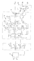
L'invention sera mieux comprise à l'aide de la description qui va suivre, donnée uniquement à titre d'exemple et faite en se référant au dessin annexé, qui représente le schéma électrique d'une interface de raccordement selon l'invention.The invention will be better understood using the description which follows, given only to by way of example and made with reference to the accompanying drawing, which represents the electrical diagram of a connection interface according to the invention.
Ainsi qu'on peut le voir sur cette figure, l'interface de raccordement selon l'invention comporte des moyens de filtrage 1 de type connu, dont les bornes d'entrée sont raccordées à des fils de transmission d'informations 2 et 3 permettant de raccorder une partie de réception d'informations d'une station, reliée à la sortie de l'interface, à un système de transmission d'informations en différentiel par deux fils, installé par exemple dans un véhicule automobile.As can be seen in this figure, the connection interface according to the invention comprises
Les moyens de filtrage 1 sont également reliés à la sortie d'un amplificateur de polarisation 4 délivrant une tension de polarisation à ces moyens de filtrage.The filter means 1 are also connected to the output of a bias amplifier 4 delivering a bias voltage to these filter means.
Les fils 2 et 3, après passage dans les moyens de filtrage, sont respectivement raccordés aux entrées non inverseuse et inverseuse d'un premier comparateur 5, dont la sortie est reliée à une borne d'entrée, désignée par la référence A, d'un multiplexeur 6 dont la sortie S est reliée au reste des circuits de la partie de réception de la station.The
Le fil de transmission 2, à la sortie des moyens de filtrage 1, est également relié à une entrée non inverseuse d'un second comparateur 7 dont l'autre entrée, c'est à dire son entrée inverseuse, est reliée à la sortie de l'amplificateur de polarisation, de manière à être portée au potentiel de polarisation délivré par celui-ci.The transmission wire 2, at the output of the filtering means 1, is also connected to a non-inverting input of a second comparator 7, the other input of which, ie its inverting input, is connected to the output of the polarization amplifier, so as to be brought to the polarization potential delivered by the latter.
La sortie de ce second comparateur 7 est également reliée directement à une entrée B du multiplexeur 6.The output of this second comparator 7 is also directly connected to an input B of the
Le fil de transmission 3 est quant à lui relié à une entrée inverseuse d'un troisième comparateur 8 dont l'autre entrée, c'est à dire son entrée non-inverseuse, est également reliée à la sortie de l'amplificateur de polarisation 4. La sortie de ce troisième comparateur 8 est reliée directement à une entrée C des moyens de multiplexage 6.The
Le multiplexeur possède également des entrées de commande D et E qui sont reliées à la sortie de moyen 9 de détection de défaut sur l'un des fils de transmission. Ces moyens de détection de défaut délivrent un mot binaire de commande du multiplexeur, pour que celui-ci sélectionne la sortie de l'un des comparateurs en fonction de l'état des fils de transmission 2 et 3, afin d'obtenir un signal de sortie non perturbé, comme cela sera décrit plus en détail par la suite.The multiplexer also has control inputs D and E which are connected to the output of fault detection means 9 on one of the transmission wires. These fault detection means deliver a binary control word for the multiplexer, so that the latter selects the output of one of the comparators as a function of the state of the
La sortie des moyens de détection 9 peut également être reliée à des moyens de mémorisation et/ou d'indication de défaut sur l'un des fils de transmission pour permettre un diagnostic en temps réel ou en temps différé du dispositif de transmission d'informations du véhicule. Ces moyens seront décrits plus en détail par la suite.The output of the detection means 9 can also be connected to storage and / or fault indication means on one of the transmission wires to allow real-time or delayed-time diagnosis of the information transmission device of the vehicle. These means will be described in more detail below.
Les entrées de commande D et E du multiplexeur sont reliées chacune à la sortie d'une porte OU 10 et 11 respectivement, dont les entrées sont reliées à des bascules montées en cascade et recevant des signaux provenant des différents comparateurs.The control inputs D and E of the multiplexer are each connected to the output of an
Ainsi par exemple, si l'on se réfère aux bascules reliées aux entrées da la porte OU 10 dont la sortie est reliée à la borne D de commande du multiplexeur, on peut constater que chaque entrée de cette porte est raccordée à deux bascules montées en cascade, respectivement 12 et 13 pour la première entrée et 14 et 15 pour la seconde entrée de cette porte.Thus for example, if we refer to the flip-flops connected to the inputs of the
Ces bascules sont constituées par exemple par des bascules du type D.These flip-flops are constituted for example by flip-flops of type D.
La bascule 12 reçoit sur l'une de ses entrées, un niveau logique 1 et sa sortie est raccordée à l'entrée de la bascule 13 dont la sortie est raccordée à l'une des entrées de la porte OU 10. Les entrées d'attaque de ces bascules reçoivent le signal de sortie du second comparateur 7, tandis que les entrées de remise à zéro de ces bascules reçoivent le signal de sortie d'un inverseur 16 dont l'entrée est reliée à la sortie du troisième comparateur 8.The flip-
Les entrées d'attaque des bascules 14 et 15 sont quant à elles reliées à la sortie d'un inverseur 17 dont l'entrée est raccordée à la sortie du second comparateur 7, tandis que les entrées de remise à zéro de ces bascules 14 et 15 sont raccordées à la sortie du troisième comparateur 8. L'entrée de la bascule 14 est raccordée à un niveau 1 logique, sa sortie étant raccordée à l'entrée de la bascule 15 dont la sortie est raccordée à l'autre entrée de la porte OU 10.The drive inputs of flip-
On peut donc constater que ces deux paires de bascules, en parallèle, fonctionnent à partir de signaux inverses dérivés des signaux de sortie des comparateurs 7 et 8.It can therefore be seen that these two pairs of flip-flops, in parallel, operate on the basis of inverse signals derived from the output signals of the comparators 7 and 8.
L'entrée de commande E du multiplexeur est quant à elle raccordée à la sortie d'une porte OU 11 dont les entrées sont également raccordées à deux paires de bascules D montées en cascade et référencées respectivement 18,19 et 20,21. Ces paires de bascules sont également connectées en parallèle sur les entrées de la partie OU 11.The control input E of the multiplexer is connected to the output of an
Les entrées d'attaque des bascules 18 et 19 sont raccordées à la sortie de l'inverseur 16, tandis que les entrées de remise à zéro de ces bascules sont raccordées directement à la sortie du second comparateur 7.The attack inputs of flip-
Les entrées d'attaque des bascules 20 et 21 sont quant à elles raccordées directement à la sortie du troisième comparateur 8, tandis que les entrées de remise à zéro de ces bascules sont raccordées à la sortie de l'inverseur 17. Les autres entrées des bascules 18 et 20 sont reliées à un niveau 1 logique, leurs sorties étant raccordées aux entrées des bascules 19 et 21 dont les sorties sont raccordées aux entrées de la porte OU 11. On conçoit également que les paires de bascules 18,19 et 20, 21 respectivement, fonctionnent à partir de signaux inversés dérivés des signaux de sortie des comparateurs 7 et 8.The drive inputs of flip-
Les moyens de détection de défaut comportent donc quatre paires de deux bascules en cascade, connectées en parallèle deux à deux, chaque bascule de chaque paire recevant des signaux d'attaque et de remise à zéro inversés par rapport à ceux reçus par la bascule correspondante de la paire associée.The fault detection means therefore comprise four pairs of two cascade flip-flops, connected in parallel two by two, each flip-flop of each pair receiving attack and reset signals inverted with respect to those received by the corresponding flip-flop of the associated pair.
Il apparaît donc que le fonctionnement d'un tel circuit permet de détecter une défaillance sur l'un ou l'autre des fils de transmission 2 ou 3, dans la mesure où les signaux d'attaque des bascules sont constitués par des signaux (directs ou inversés) circulant sur l'un des fils tandis que les signaux de remise à zéro de ces bascules sont constitués par des signaux (directs ou inversés) circulant sur l'autre fil.It therefore appears that the operation of such a circuit makes it possible to detect a failure on one or the other of the
Dans la mesure où le dispositif fonctionne de manière normale, c'est à dire en différentiel, on retrouve donc sur les fils 2 et 3 deux signaux inver sés l'un par rapport à l'autre. Les signaux circulant sur l'un des fils servent à attaquer les bascules, tandis que les signaux circulant sur l'autre fil servent à remettre celles-ci à zéro.Insofar as the device operates normally, that is to say in differential, there are therefore on the
En cas de défaut de transmission sur l'un ou l'autre des fils de transmission, les bascules correspondantes ne sont pas remises à zéro et on retrouve donc en sortie des paires de bascules concernées, un niveau logique 1 qui se retrouve également à la sortie des bascules 10 ou 11, c'est à dire en F1 ou en F2, ces sorties étant raccordées aux entrées de commande D et E du multiplexeur 6 pour amener celui-ci à sélectionner la sortie de l'un des comparateurs en fonction de l'état des fils de transmission.In the event of a transmission fault on one or the other of the transmission wires, the corresponding flip-flops are not reset and there is therefore at the output of the pairs of flip-flops concerned, a
Le tableau suivant illustre les différentes possibilités de fonctionnement de l'interface selon l'invention.
On voit donc apparaître à la lueur de ce tableau que lorsque deux signaux inversés circulent sur les lignes 2 et 3, ils se neutralisent mutuellement, de manière qu'en sortie des bascules 10 et 11, on retrouve un mot binaire 00, ce mot binaire atta quant le multiplexeur pour que celui-ci connecte sa borne d'entrée A à sa sortie S de manière à délivrer en sortie vers le reste des circuits de la station, le signal de sortie du comparateur 5.We thus see appear in the glare of this table that when two reversed signals circulate on
Par contre, en cas de défaut sur le fil 2, la sortie F2 de la porte 11 passe à 1, et le mot binaire 01 est donc appliqué aux entrées D,E du multiplexeur 6, de manière que celui-ci raccorde son entrée C à sa sortie de manière à sélectionner la sortie du troisième comparateur 8.On the other hand, in the event of a fault on wire 2, the output F2 of
En cas de défaut sur le fil 3, la sortie F1 de la porte 10 passe à 1 et le mot binaire 1 0 est appliqué aux entrées de commande D,E du multiplexeur, de manière que celui-ci raccorde son entrée B à sa sortie et sélectionne ainsi la sortie du second comparateur 7.In the event of a fault on
Les signaux présente en sortie des comparateurs 7 et 8 représentent les signaux circulant sur les fils 2 et 3 respectivement, ces signaux ne pouvant pas être perturbés par des défauts éventuels sur l'autre fil en raison de la séparation de l'analyse de ceux-ci dans deux comparateurs différents attaqués par une tension de polarisation.The signals present at the output of the comparators 7 and 8 represent the signals circulating on the
Afin de faciliter le diagnostic et la réparation du dispositif de transmission du véhicule lorsque celui-ci présente des défauts, des moyens d'indication de défaut 22 peuvent également être connectés à la sortie des moyens de détection de défaut 9. Ces moyens d'indication de défaut 22 peuvent comprendre deux lampes 23 et 24 raccordées dans les circuits de collecteur de transistors 25, 26 dont les bases sont reliées respectivement à la sortie F1 de la porte OU 10 et à la sortie F2 de la porte OU 11.In order to facilitate the diagnosis and repair of the vehicle transmission device when it has faults, fault indication means 22 can also be connected to the output of fault detection means 9. These means of
Ces lampes permettent d'indiquer l'existence d'un défaut sur l'un ou l'autre des fils de transmission par exemple à un utilisateur de véhicule ou à une personne chargée de son entretien. Il va de soi que ces moyens d'indication peuvent également être remplacés par des moyens de mémorisation de défaut, ces moyens de mémorisation pouvant être lus par des équipements de diagnostic appropriés.These lamps indicate the existence a fault on one or other of the transmission wires, for example to a vehicle user or a person responsible for its maintenance. It goes without saying that these means of indication can also be replaced by means of fault memorization, these memorizing means being able to be read by appropriate diagnostic equipment.
Claims (6)
Applications Claiming Priority (2)
| Application Number | Priority Date | Filing Date | Title |
|---|---|---|---|
| FR8801598 | 1988-02-10 | ||
| FR8801598A FR2627036B1 (en) | 1988-02-10 | 1988-02-10 | INTERFACE FOR CONNECTING AN INFORMATION RECEPTION PART OF A STATION IN A DIFFERENTIAL INFORMATION TRANSMISSION SYSTEM, BY TWO TRANSMISSION WIRES, PARTICULARLY IN A MOTOR VEHICLE |
Publications (2)
| Publication Number | Publication Date |
|---|---|
| EP0329514A1 true EP0329514A1 (en) | 1989-08-23 |
| EP0329514B1 EP0329514B1 (en) | 1992-12-16 |
Family
ID=9363161
Family Applications (1)
| Application Number | Title | Priority Date | Filing Date |
|---|---|---|---|
| EP89400303A Expired - Lifetime EP0329514B1 (en) | 1988-02-10 | 1989-02-02 | Connecting interface for an information transmission system, e.g. for an automotive vehicle |
Country Status (5)
| Country | Link |
|---|---|
| US (1) | US5031176A (en) |
| EP (1) | EP0329514B1 (en) |
| JP (1) | JP2749100B2 (en) |
| DE (1) | DE68903843T2 (en) |
| FR (1) | FR2627036B1 (en) |
Cited By (7)
| Publication number | Priority date | Publication date | Assignee | Title |
|---|---|---|---|---|
| FR2653281A1 (en) * | 1989-10-17 | 1991-04-19 | Renault | Line interface for an information transmission network |
| EP0427638A1 (en) * | 1989-11-10 | 1991-05-15 | Regie Nationale Des Usines Renault S.A. | Line interface for an information transmission network |
| WO1991017615A2 (en) * | 1990-05-08 | 1991-11-14 | Caterpillar Inc. | Diagnostic hardware for serial datalink |
| FR2673788A1 (en) * | 1991-03-05 | 1992-09-11 | Siemens Automotive Sa | Method of transmitting frames of digital data sent on a differential bus |
| EP0506237A2 (en) * | 1991-02-26 | 1992-09-30 | Nippondenso Co., Ltd. | A communication apparatus with fault tolerance |
| EP0527076A1 (en) * | 1991-08-07 | 1993-02-10 | Automobiles Peugeot | Differential information transmission between at least two parts of a vehicle |
| EP0529602A2 (en) * | 1991-08-27 | 1993-03-03 | The Furukawa Electric Co., Ltd. | Differential receiver which is tolerant of line faults |
Families Citing this family (13)
| Publication number | Priority date | Publication date | Assignee | Title |
|---|---|---|---|---|
| DE3826774A1 (en) * | 1988-08-06 | 1990-02-08 | Bosch Gmbh Robert | NETWORK INTERFACE |
| JP2851124B2 (en) * | 1990-04-27 | 1999-01-27 | 古河電気工業株式会社 | Multiplex transmission method |
| US5282193A (en) * | 1990-11-24 | 1994-01-25 | Fujitsu Limited | Maintenance signal transmission system |
| WO1992010897A1 (en) * | 1990-12-04 | 1992-06-25 | The Furukawa Electric Co., Ltd. | Voltage setting apparatus in multiplex transmission system |
| DE69231289T2 (en) * | 1991-10-16 | 2001-01-04 | Furukawa Electric Co Ltd | Multiplex transmission system |
| JP3133499B2 (en) * | 1991-10-16 | 2001-02-05 | 古河電気工業株式会社 | Multiplex transmission method |
| US5454001A (en) * | 1993-04-16 | 1995-09-26 | Honda Giken Kogyo Kabushiki Kaisha | Data transmission system for automotive vehicles |
| DE19509133C2 (en) * | 1994-04-11 | 2003-07-17 | Daimler Chrysler Ag | Arrangement for monitoring two-wire bus lines |
| US5701410A (en) * | 1996-09-09 | 1997-12-23 | Ford Motor Company | Method and system for detecting fault conditions on multiplexed networks |
| JP3325851B2 (en) * | 1999-04-02 | 2002-09-17 | 本田技研工業株式会社 | Communication system failure detection device |
| DE10109558C1 (en) * | 2001-02-28 | 2003-01-30 | Siemens Ag | Additional circuit on the receiver side for the boundary scan during data transmission with differential signals |
| US7148723B2 (en) * | 2002-01-30 | 2006-12-12 | Caterpillar Inc | Common controller area network interface |
| CN104554074B (en) * | 2013-10-25 | 2017-09-15 | 通用电气公司 | Vehicle control system |
Citations (6)
| Publication number | Priority date | Publication date | Assignee | Title |
|---|---|---|---|---|
| US3609662A (en) * | 1969-10-23 | 1971-09-28 | Sperry Rand Corp | Serial pulse digital transmission system |
| GB1314024A (en) * | 1969-11-13 | 1973-04-18 | Ultra Electronics Ltd | Communications systems |
| US3803355A (en) * | 1971-08-03 | 1974-04-09 | Siemens Ag | Apparatus for line supervision for wire breaks in data transmission systems |
| US4165491A (en) * | 1976-11-08 | 1979-08-21 | Sperry Rand Corporation | Circuit for detecting zero crossing points for data signal |
| DE3342763A1 (en) * | 1983-11-25 | 1985-06-05 | Siemens AG, 1000 Berlin und 8000 München | Circuit arrangement for monitoring balanced lines |
| FR2575014A1 (en) * | 1984-12-18 | 1986-06-20 | Motorola Inc | SIGNAL RECEIVER ADMITTING A DANGER |
Family Cites Families (5)
| Publication number | Priority date | Publication date | Assignee | Title |
|---|---|---|---|---|
| US3476922A (en) * | 1966-08-05 | 1969-11-04 | Sperry Rand Corp | Failure monitor for redundant channel systems |
| JPS53132934A (en) * | 1977-04-26 | 1978-11-20 | Mitsubishi Electric Corp | Detector for abnormal state of data transmitter |
| US4271515A (en) * | 1979-03-23 | 1981-06-02 | John Fluke Mfg. Co., Inc. | Universal analog and digital tester |
| US4245344A (en) * | 1979-04-02 | 1981-01-13 | Rockwell International Corporation | Processing system with dual buses |
| US4792950A (en) * | 1987-06-17 | 1988-12-20 | Ford Motor Company | Multiplex wiring system |
-
1988
- 1988-02-10 FR FR8801598A patent/FR2627036B1/en not_active Expired - Lifetime
-
1989
- 1989-02-02 DE DE8989400303T patent/DE68903843T2/en not_active Expired - Lifetime
- 1989-02-02 EP EP89400303A patent/EP0329514B1/en not_active Expired - Lifetime
- 1989-02-09 US US07/308,028 patent/US5031176A/en not_active Expired - Lifetime
- 1989-02-10 JP JP1032513A patent/JP2749100B2/en not_active Expired - Lifetime
Patent Citations (6)
| Publication number | Priority date | Publication date | Assignee | Title |
|---|---|---|---|---|
| US3609662A (en) * | 1969-10-23 | 1971-09-28 | Sperry Rand Corp | Serial pulse digital transmission system |
| GB1314024A (en) * | 1969-11-13 | 1973-04-18 | Ultra Electronics Ltd | Communications systems |
| US3803355A (en) * | 1971-08-03 | 1974-04-09 | Siemens Ag | Apparatus for line supervision for wire breaks in data transmission systems |
| US4165491A (en) * | 1976-11-08 | 1979-08-21 | Sperry Rand Corporation | Circuit for detecting zero crossing points for data signal |
| DE3342763A1 (en) * | 1983-11-25 | 1985-06-05 | Siemens AG, 1000 Berlin und 8000 München | Circuit arrangement for monitoring balanced lines |
| FR2575014A1 (en) * | 1984-12-18 | 1986-06-20 | Motorola Inc | SIGNAL RECEIVER ADMITTING A DANGER |
Non-Patent Citations (1)
| Title |
|---|
| PATENT ABSTRACTS OF JAPAN, vol. 3, no. 5 (E-84), 18 janvier 1979, page 144 E 84; & JP-A-53 132 934 (MITSUBISHI DENKI K.K.) 20-11-1978 * |
Cited By (16)
| Publication number | Priority date | Publication date | Assignee | Title |
|---|---|---|---|---|
| FR2653281A1 (en) * | 1989-10-17 | 1991-04-19 | Renault | Line interface for an information transmission network |
| EP0427638A1 (en) * | 1989-11-10 | 1991-05-15 | Regie Nationale Des Usines Renault S.A. | Line interface for an information transmission network |
| FR2654564A1 (en) * | 1989-11-10 | 1991-05-17 | Renault | LINE INTERFACE FOR AN INFORMATION TRANSMISSION NETWORK. |
| US5267251A (en) * | 1989-11-10 | 1993-11-30 | Regie Nationale Des Usines Renault S.A. | Line interface for a data transmission network |
| WO1991017615A3 (en) * | 1990-05-08 | 1991-12-12 | Caterpillar Inc | Diagnostic hardware for serial datalink |
| AU640691B2 (en) * | 1990-05-08 | 1993-09-02 | Caterpillar Inc. | Diagnostic hardware for serial datalink |
| WO1991017615A2 (en) * | 1990-05-08 | 1991-11-14 | Caterpillar Inc. | Diagnostic hardware for serial datalink |
| EP0506237A2 (en) * | 1991-02-26 | 1992-09-30 | Nippondenso Co., Ltd. | A communication apparatus with fault tolerance |
| EP0506237A3 (en) * | 1991-02-26 | 1995-05-17 | Nippon Denso Co | A communication apparatus with fault tolerance |
| FR2673788A1 (en) * | 1991-03-05 | 1992-09-11 | Siemens Automotive Sa | Method of transmitting frames of digital data sent on a differential bus |
| EP0527076A1 (en) * | 1991-08-07 | 1993-02-10 | Automobiles Peugeot | Differential information transmission between at least two parts of a vehicle |
| FR2680294A1 (en) * | 1991-08-07 | 1993-02-12 | Peugeot | DEVICE FOR TRANSMITTING DIFFERENTIAL INFORMATION BETWEEN AT LEAST TWO ORGANS OF A MOTOR VEHICLE. |
| US5347543A (en) * | 1991-08-07 | 1994-09-13 | Automobiles Peugeot | Device for differential-mode information transmission between at least two elements of a motor vehicle |
| EP0529602A2 (en) * | 1991-08-27 | 1993-03-03 | The Furukawa Electric Co., Ltd. | Differential receiver which is tolerant of line faults |
| EP0529602A3 (en) * | 1991-08-27 | 1993-07-07 | The Furukawa Electric Co., Ltd. | Differential receiver which is tolerant of line faults |
| US5295132A (en) * | 1991-08-27 | 1994-03-15 | The Furukawa Electric Co., Ltd. | Multiplex transmission apparatus with transmission line fault detection |
Also Published As
| Publication number | Publication date |
|---|---|
| FR2627036A1 (en) | 1989-08-11 |
| FR2627036B1 (en) | 1990-07-27 |
| JP2749100B2 (en) | 1998-05-13 |
| US5031176A (en) | 1991-07-09 |
| DE68903843D1 (en) | 1993-01-28 |
| EP0329514B1 (en) | 1992-12-16 |
| JPH0220998A (en) | 1990-01-24 |
| DE68903843T2 (en) | 1993-06-09 |
Similar Documents
| Publication | Publication Date | Title |
|---|---|---|
| EP0329514B1 (en) | Connecting interface for an information transmission system, e.g. for an automotive vehicle | |
| EP0318354B1 (en) | Vehicle data transmission device and method for using said device | |
| EP0322272A1 (en) | Transmission system between several units of a motor vehicle and a central processing unit | |
| FR2645649A1 (en) | DEVICE FOR THE CORRECT FUNCTIONAL CONTROL OF A SWITCH ANALYZING THE CLOSURE STATUS OF A SEAT BELT IN A MOTOR VEHICLE | |
| DE102018204615A1 (en) | Sensor arrangement for a vehicle | |
| FR2666418A1 (en) | DEVICE FOR CAPTURING DIAGNOSTIC DATA FROM ELECTRONIC UNITS IN A MOTOR VEHICLE. | |
| WO2015049045A1 (en) | Device for diagnosing the loss of a connection between an electronic control module and a ground | |
| FR2490842A1 (en) | ELECTRONIC ADAPTER DEVICE OF A DIAGNOSTIC SOCKET WITH INFORMATION PROVIDED BY AN ELECTRONIC CONTROL CIRCUIT | |
| EP0482965B1 (en) | Method and device for testing a dataprocessing module and its application in vehicle electronics | |
| CA2877394A1 (en) | Electric circuit for cutting off an electric power supply having transistors and fuses | |
| FR2813833A1 (en) | Device for control/regulation of the various functioning units of an automotive vehicle, e.g. engine control, gearbox control, anti-lock braking system, central locking, air-bags etc. | |
| FR2653279A1 (en) | Information coding device especially for a changeover switch in motor vehicles | |
| FR2944661A1 (en) | NON-INTRUSTIVE DEVICE FOR DIAGNOSING FAULT (S) OF OPERATION IN AT LEAST ONE COMMUNICATION NETWORK | |
| FR2596216A1 (en) | DEVICE FOR POWER SUPPLYING A CENTRAL UNIT BY AT LEAST ONE CONTROL SIGNAL, WHICH UNIT IS CONNECTED TO AT LEAST ONE RECEIVING LOCAL STATION | |
| FR3007530A1 (en) | DEVICE FOR DIAGNOSING THE LOSS OF A CONNECTION BETWEEN AN ELECTRONIC CONTROL MODULE AND A MASS | |
| FR3082960A1 (en) | ELECTRONIC ARCHITECTURE OF MOTOR VEHICLE WITH REDUNDANCY OF POWER SUPPLY AND INTER-COMPUTER COMMUNICATION NETWORKS. | |
| EP1052131B1 (en) | Device for detecting the presence of a tank cap of a motor vehicle | |
| FR3104115A1 (en) | Device for monitoring, on board a motor vehicle, the operation of a vehicle speaker and vehicle fitted with such a device | |
| FR2710886A1 (en) | Blinking system of change of direction and warning for a motor vehicle. | |
| EP0147264B1 (en) | Static diagnostic apparatus for ignition systems | |
| FR2622853A1 (en) | METHOD FOR CONTROLLING A REAR WIPER AND DEVICE FOR IMPLEMENTING THE METHOD, IN PARTICULAR WITH INTERMITTENT OPERATION CONTROL | |
| FR2715475A1 (en) | Method and device for controlling an electronic sensor fitted to a motor vehicle equipped with an "anti-lock-safety" braking system. | |
| FR3044985A1 (en) | VEHICLE REAR LIGHT, VEHICLE SIGNALING AND LIGHTING SYSTEM AND VEHICLE | |
| FR3049416A1 (en) | CAN SPECIFIC IMPEDANCE COMMUNICATION ARMOR | |
| EP3028425B1 (en) | Apparatus for communication and vehicle comprising such an apparatus |
Legal Events
| Date | Code | Title | Description |
|---|---|---|---|
| PUAI | Public reference made under article 153(3) epc to a published international application that has entered the european phase |
Free format text: ORIGINAL CODE: 0009012 |
|
| AK | Designated contracting states |
Kind code of ref document: A1 Designated state(s): DE GB IT SE |
|
| 17P | Request for examination filed |
Effective date: 19890705 |
|
| 17Q | First examination report despatched |
Effective date: 19920505 |
|
| ITF | It: translation for a ep patent filed |
Owner name: INVENTION S.N.C. |
|
| GRAA | (expected) grant |
Free format text: ORIGINAL CODE: 0009210 |
|
| AK | Designated contracting states |
Kind code of ref document: B1 Designated state(s): DE GB IT SE |
|
| REF | Corresponds to: |
Ref document number: 68903843 Country of ref document: DE Date of ref document: 19930128 |
|
| GBT | Gb: translation of ep patent filed (gb section 77(6)(a)/1977) |
Effective date: 19930305 |
|
| PLBE | No opposition filed within time limit |
Free format text: ORIGINAL CODE: 0009261 |
|
| STAA | Information on the status of an ep patent application or granted ep patent |
Free format text: STATUS: NO OPPOSITION FILED WITHIN TIME LIMIT |
|
| 26N | No opposition filed | ||
| EAL | Se: european patent in force in sweden |
Ref document number: 89400303.7 |
|
| REG | Reference to a national code |
Ref country code: GB Ref legal event code: IF02 |
|
| PGFP | Annual fee paid to national office [announced via postgrant information from national office to epo] |
Ref country code: IT Payment date: 20080213 Year of fee payment: 20 Ref country code: DE Payment date: 20080208 Year of fee payment: 20 Ref country code: SE Payment date: 20080125 Year of fee payment: 20 Ref country code: GB Payment date: 20080129 Year of fee payment: 20 |
|
| REG | Reference to a national code |
Ref country code: GB Ref legal event code: PE20 Expiry date: 20090201 |
|
| EUG | Se: european patent has lapsed | ||
| PG25 | Lapsed in a contracting state [announced via postgrant information from national office to epo] |
Ref country code: GB Free format text: LAPSE BECAUSE OF EXPIRATION OF PROTECTION Effective date: 20090201 |