EP0326236A2 - Method of setting up apparatus for handling electrical or electronic components - Google Patents
Method of setting up apparatus for handling electrical or electronic components Download PDFInfo
- Publication number
- EP0326236A2 EP0326236A2 EP89300030A EP89300030A EP0326236A2 EP 0326236 A2 EP0326236 A2 EP 0326236A2 EP 89300030 A EP89300030 A EP 89300030A EP 89300030 A EP89300030 A EP 89300030A EP 0326236 A2 EP0326236 A2 EP 0326236A2
- Authority
- EP
- European Patent Office
- Prior art keywords
- plate
- array
- setting
- fiducial marks
- reference point
- Prior art date
- Legal status (The legal status is an assumption and is not a legal conclusion. Google has not performed a legal analysis and makes no representation as to the accuracy of the status listed.)
- Ceased
Links
Images
Classifications
-
- H—ELECTRICITY
- H05—ELECTRIC TECHNIQUES NOT OTHERWISE PROVIDED FOR
- H05K—PRINTED CIRCUITS; CASINGS OR CONSTRUCTIONAL DETAILS OF ELECTRIC APPARATUS; MANUFACTURE OF ASSEMBLAGES OF ELECTRICAL COMPONENTS
- H05K13/00—Apparatus or processes specially adapted for manufacturing or adjusting assemblages of electric components
- H05K13/08—Monitoring manufacture of assemblages
- H05K13/089—Calibration, teaching or correction of mechanical systems, e.g. of the mounting head
Definitions
- This invention relates to a method of setting up apparatus for handling electrical or electronic components, for example in a component placement machine.
- the components may be of a variety of shapes and sizes, for example so-called flat packs, S.O style transistors, leadless chip carriers, dual in line packages, melf type components and the like, as well as so-called "chips".
- a suitable substrate for example a printed circuit board.
- a number of systems have been proposed for handling the components to be placed on a substrate and many of these have proposed the use of pick-up heads having a suitable tool by which a component may be picked up.
- the tools have been of various types, depending to some extent on the components to be handled; for example the tools may grip the components mechanically or may use suction or a magnetic system to retain a component on the tool of the pick-up head when the component is removed from a suitable component supply means for delivery elsewhere, for example to a suitable placement position where the component may be placed on a substrate e.g. a printed circuit board. It is important to ensure that the components are correctly oriented when placed on the substrate and a number of methods have been proposed to attempt to ensure correct orientation.
- the substrate for example a printed circuit board, on which the components are to be placed, is mounted in an accurately known position on an X-Y table, suitably mounted on a frame.
- the X-Y table may be mounted and driven by any suitable. means, a number of which are known, and one such means for mounting and driving an X-Y table is described by way of example in our PCT Patent Application Publication No. W.O. 85/03404.
- the movement of the X-Y table can in theory be determined accurately and precisely by control of its drive mechanism, there can in practice be some deviation between the theoretical and the actual response of the table to the drive mechanism. This can result in a deviation from the intended location of the X-Y table, and hence the substrate mounted on it, which can lead to inaccurate placement of a component on the substrate.
- Patent Specification No. 1 142 774 has addressed the problem of deviations in X-Y response in relation to numerically controlled devices such as plotters, machine tools or the like.
- the method described in that patent specification involves driving a part to a number of different positions relative to a reference member, detecting the true position of the part using a measuring device such as a laser interferometer, and storing a table of error values for future use in correcting table drive.
- This method requires the presence of a very accurate measuring device for measuring the parts position relative to the origin of the X-Y table coordinate system whenever the X-Y table is calibrated.
- PCT Patent Specification No. WO 85/03368 describes a calibrating system in which a plate with calibration marks thereon is mounted on a table which is movable in the X direction beneath a head which is movable in the Y direction.
- the x drive is utilised to drive to an x value which should correspond to a calibration point. If the calibration point is not located under a calibration probe used to provide a reference point, the x drive is utilised to move the plate by small amounts until the point is correctly located. The procedure is then repeated for y values using the same or a different, but nearby calibration point.
- This system is not concerned with an X-Y table and is time consuming since numerous attempts may be necessary to detect the calibration point in the x direction, as the calibration probe is only able to detect whether or not the point is correctly located, and then further attempts may be necessary for the y direction.
- An object of the present invention is to provide an improved method of setting up a component placement machine in which any inaccuracy in the positioning of a point on a substrate mounted on the X-Y table relative to a reference point, which inaccuracy is due to the response of the X-Y table to its drive system, is reduced or substantially obviated.
- the invention provides a method of setting up a component placement machine, comprising a pick-up head having a pick-up tool, and an X-Y table on which substrates on which components are to be placed may be mounted to account for errors in the X-Y table drive utilising a detecting device having a two dimensional field of view and operable to detect the position of a fiducial mark, as herein defined, within said field of view relative to a reference point of the device, characterised in that the method comprises the steps of:
- facial mark where used herein is to be understood a mark whose position is precisely known relative to location points of a plate on which the mark is located.
- corrections can be made for the errors in the X-Y table drive.
- the known errors in driving to the positions of fiducial marks adjacent to said particular position can be taken into account to produce a more accurate drive.
- the method further comprises the steps of:
- step (e) enable the x,y coordinates of the actual positions of fiducial marks to be determined from the known coordinates of the fiducial marks relative to the plate.
- algorithims may be calculated for the x and y drive corrections to any point within that area based on the known x,y coordinates of the fiducial marks around said area (e.g. at the corners of a rectangular area) and on the x,y coordinates of the detected actual positions of said marks.
- the detecting device preferably used in the method according to the invention is a pattern recognition camera, in particular a charge coupled device (CCD) camera, in which an array of sensors survey the field of view, and can detect and record the x,y coordinates of a point in the field of view relative to a reference point of the camera.
- the point in the field of view is the fiducial mark.
- a camera in particular, a CCD camera, makes it possible for the position of the fiducial mark to be detected and recorded quickly and accurately.
- the setting-up plate for use in the method according to the invention preferably comprises an aluminium plate, provided with an array of fiducial marks as hereinbefore defined. Aluminium is particularly suitable for the setting-up plate for use in the method according to the invention because of its behaviour with respect to small variations in temperature such as are likely to occur in the operating conditions of the method according to the invention and because it can easily be accurately formed.
- the setting-up plate for use in the method according to the invention is provided with an array of fiducial marks as hereinbefore defined.
- the fiducial marks are preferably in the form of pins attached to the setting-up plate, suitably drilled into the plate. Pins are particularly suitable for use as fiducial marks, as their position can be reliably determined by the detecting device, for example the CCD camera.
- the fiducial marks are arranged in an array, preferably a regular rectangular array. It is preferred to position the fiducial marks in a regular rectangular array, for ease of computation of the errors in the X-Y table drive and calculation of the necessary corrections. It has in practice been found that an array of sixteen fiducial marks, arranged in a four by four array equally spaced across the setting-up plate, provides sufficient information to establish the errors in the drive of an X-Y table within satisfactory limits, and does not require excessive computation.
- the setting-up plate for use in the method according to the invention preferably comprises an array of sixteen fiducial marks arranged in a regular rectangular array.
- the preferred method is used for setting-up a component placement machine to account for errors in the X-Y table drive thereof.
- the machine comprises a CCD camera (not shown) looking downwards at the X-Y table and having a reference point at the centre of its two dimensional field of view.
- the CCD camera used may be that normally present in some machines for detecting location marks of printed circuits on a printed circuit board.
- a setting-up plate (1) is mounted in an accurately known position on the X-Y table by means of aligning location points (3) of the X-Y table and the setting-up plate.
- the plate (1) comprises an aluminium plate on which are mounted sixteen pins (2) in a four by four array.
- the distances a1, a2, a3 etc. between adjacent pins in the x-direction are nominally the same and the distances b1, b2, b3 etc. between adjacent pins in the y-direction, are also nominally the same though not necessarily the same as the inter-pin distances in the x-direction, and are measured accurately for every inter-pin distance by known means.
- the temperature at which these measurements are carried out is recorded and is marked on the plate.
- the setting up is carried out at a temperature within about 5°C of the measuring temperature in order substantially to obviate any error due to thermal expansion or contraction of the setting-up plate.
- the area of the plate (1) covered by the array of pins (2) is substantially equal to the effective working area of the X-Y table, that is the area on which components are to be placed, on a substrate which is to be mounted on the table.
- the pins are drilled into the plate to ensure secure fixing, and each pin may be provided with a collar (4), suitably of black rubber, to give a dark background to the pin to assist detection by the camera.
- control system of the X-Y table is informed of the x,y coordinates of each of the pins on the setting-up plate mounted on the X-Y table, and the X-Y table is driven by means of its control system to the position where the reference point of the CCD camera is expected to coincide with a first pin i.e. the drive attempts to position the table so that the reference point of the camera is at the known x-y coordinates of the first pin.
- the actual position of the pin relative to the reference point is detected using the CCD camera, and the x and y distances between the actual position and said reference point are determined by counting the number of pixels in the field of view of the camera between the detected actual position and the reference point. Thus, the error at the pin is determined.
- the X-Y table is then driven by means of its control system to the position where the reference point of the CCD camera is expected to coincide with the known x,y coordinates of a second pin, and the steps of detection, and determining distances are repeated for this pin.
- the X-Y table is then driven under its control system to each pin position, applying a correction which takes account of the errors determined, and the CCD camera is used to check that the actual position of each pin is within acceptably small x and y distances from the reference point. If not, the method is repeated for that pin.
- the setting-up plate is then removed from the X-Y table, and the component placement machine can be used for the placing of components on a substrate.
- the component placement machine can be used for the placing of components on a substrate.
- the x axis scaling factor is given by (D x - C x )/(d x - c x ) and this is multiplied by x to give the corrected value X at any point along the line between c and d.
- the scaling factor K (D x - C x - d x ⁇ c x )/(d x - c x ).
- Axis skew on line c to a is ((A x - C x ) - (a x - c x ))/(a y - c y )
- X ((A x - C x - a x ⁇ c x )/(a y - c y ))
- y X Ny
- N (A x - C x - a x ⁇ c x )/(a y - c y ).
- Y y ⁇ Py ⁇ Sxy ⁇ Tx, which is the algorithm for y drive correction
- P (A y - C y - a y ⁇ c y )/(a y - c y )
- S (R - P)/(d x - c x )
- R (B y - D y - b y ⁇ d y )/(b y - d y )
- T (D y - C y - d y ⁇ c y )/(d x - c x ).
Landscapes
- Engineering & Computer Science (AREA)
- Operations Research (AREA)
- Manufacturing & Machinery (AREA)
- Microelectronics & Electronic Packaging (AREA)
- Supply And Installment Of Electrical Components (AREA)
- Control Of Position Or Direction (AREA)
Abstract
Description
- This invention relates to a method of setting up apparatus for handling electrical or electronic components, for example in a component placement machine. The components may be of a variety of shapes and sizes, for example so-called flat packs, S.O style transistors, leadless chip carriers, dual in line packages, melf type components and the like, as well as so-called "chips".
- In the manufacture of electrical or electronic apparatus it is necessary to assemble a plurality of components on a suitable substrate, for example a printed circuit board. A number of systems have been proposed for handling the components to be placed on a substrate and many of these have proposed the use of pick-up heads having a suitable tool by which a component may be picked up. The tools have been of various types, depending to some extent on the components to be handled; for example the tools may grip the components mechanically or may use suction or a magnetic system to retain a component on the tool of the pick-up head when the component is removed from a suitable component supply means for delivery elsewhere, for example to a suitable placement position where the component may be placed on a substrate e.g. a printed circuit board. It is important to ensure that the components are correctly oriented when placed on the substrate and a number of methods have been proposed to attempt to ensure correct orientation.
- In component placement machines of the type described, the substrate, for example a printed circuit board, on which the components are to be placed, is mounted in an accurately known position on an X-Y table, suitably mounted on a frame. The X-Y table may be mounted and driven by any suitable. means, a number of which are known, and one such means for mounting and driving an X-Y table is described by way of example in our PCT Patent Application Publication No. W.O. 85/03404.
- Whilst the movement of the X-Y table can in theory be determined accurately and precisely by control of its drive mechanism, there can in practice be some deviation between the theoretical and the actual response of the table to the drive mechanism. This can result in a deviation from the intended location of the X-Y table, and hence the substrate mounted on it, which can lead to inaccurate placement of a component on the substrate.
- Clearly if this inaccuracy in placement of the component exceeds any permissible tolerance, then an unacceptably high reject rate for the completed substrates will result.
- G.B. Patent Specification No. 1 142 774 has addressed the problem of deviations in X-Y response in relation to numerically controlled devices such as plotters, machine tools or the like. The method described in that patent specification involves driving a part to a number of different positions relative to a reference member, detecting the true position of the part using a measuring device such as a laser interferometer, and storing a table of error values for future use in correcting table drive. This method requires the presence of a very accurate measuring device for measuring the parts position relative to the origin of the X-Y table coordinate system whenever the X-Y table is calibrated.
- PCT Patent Specification No. WO 85/03368 describes a calibrating system in which a plate with calibration marks thereon is mounted on a table which is movable in the X direction beneath a head which is movable in the Y direction. The x drive is utilised to drive to an x value which should correspond to a calibration point. If the calibration point is not located under a calibration probe used to provide a reference point, the x drive is utilised to move the plate by small amounts until the point is correctly located. The procedure is then repeated for y values using the same or a different, but nearby calibration point. This system is not concerned with an X-Y table and is time consuming since numerous attempts may be necessary to detect the calibration point in the x direction, as the calibration probe is only able to detect whether or not the point is correctly located, and then further attempts may be necessary for the y direction.
- An object of the present invention is to provide an improved method of setting up a component placement machine in which any inaccuracy in the positioning of a point on a substrate mounted on the X-Y table relative to a reference point, which inaccuracy is due to the response of the X-Y table to its drive system, is reduced or substantially obviated.
- The invention provides a method of setting up a component placement machine, comprising a pick-up head having a pick-up tool, and an X-Y table on which substrates on which components are to be placed may be mounted to account for errors in the X-Y table drive utilising a detecting device having a two dimensional field of view and operable to detect the position of a fiducial mark, as herein defined, within said field of view relative to a reference point of the device, characterised in that the method comprises the steps of:
- (a) mounting a setting-up plate, provided with an array of fiducial marks, having accurately known x,y coordinates relative to the plate, in an accurately known position on the X-Y table by means of aligning location points of the X-Y table and the setting-up plate;
- (b) informing a control system of the table drive of said known x,y coordinates of the fiducial marks in the array;
- (c) causing the control system to drive the X-Y table to a position where the reference point of the detecting device is expected to coincide with one of said fiducial marks;
- (d) utilising the detecting device to detect the actual position of said mark relative to the reference point;
- (e) determining the x and y distances between said actual position and said reference point and;
- (f) repeating steps (c) to (e) for each mark in the array.
- By the term "fiducial mark" where used herein is to be understood a mark whose position is precisely known relative to location points of a plate on which the mark is located.
- By utilising a method according to the last but one preceding paragraph, corrections can be made for the errors in the X-Y table drive. In driving to a particular position, the known errors in driving to the positions of fiducial marks adjacent to said particular position can be taken into account to produce a more accurate drive.
- In a preferred embodiment of the method according to the invention, the method further comprises the steps of:
- (g) driving the X-Y table to the fiducial mark positions applying a correction which takes account of the distances determined in step (e) and
- (h) checking that the actual position of each fiducial mark is within acceptably small x and y distances from the reference point.
- By incorporating steps (g) and (h) in the method according to the invention, it is possible to confirm that appropriate corrections are being made for the errors in the X-Y table drive.
- The distances determined in step (e) enable the x,y coordinates of the actual positions of fiducial marks to be determined from the known coordinates of the fiducial marks relative to the plate. Hence, for each area within the array of fiducial marks (e.g. a rectangular area between four such marks) algorithims may be calculated for the x and y drive corrections to any point within that area based on the known x,y coordinates of the fiducial marks around said area (e.g. at the corners of a rectangular area) and on the x,y coordinates of the detected actual positions of said marks.
- The detecting device preferably used in the method according to the invention is a pattern recognition camera, in particular a charge coupled device (CCD) camera, in which an array of sensors survey the field of view, and can detect and record the x,y coordinates of a point in the field of view relative to a reference point of the camera. In the method according to the present invention, the point in the field of view is the fiducial mark. The use of a camera, in particular, a CCD camera, makes it possible for the position of the fiducial mark to be detected and recorded quickly and accurately.
- The setting-up plate for use in the method according to the invention preferably comprises an aluminium plate, provided with an array of fiducial marks as hereinbefore defined. Aluminium is particularly suitable for the setting-up plate for use in the method according to the invention because of its behaviour with respect to small variations in temperature such as are likely to occur in the operating conditions of the method according to the invention and because it can easily be accurately formed.
- The setting-up plate for use in the method according to the invention is provided with an array of fiducial marks as hereinbefore defined. The fiducial marks are preferably in the form of pins attached to the setting-up plate, suitably drilled into the plate. Pins are particularly suitable for use as fiducial marks, as their position can be reliably determined by the detecting device, for example the CCD camera.
- The fiducial marks are arranged in an array, preferably a regular rectangular array. It is preferred to position the fiducial marks in a regular rectangular array, for ease of computation of the errors in the X-Y table drive and calculation of the necessary corrections. It has in practice been found that an array of sixteen fiducial marks, arranged in a four by four array equally spaced across the setting-up plate, provides sufficient information to establish the errors in the drive of an X-Y table within satisfactory limits, and does not require excessive computation. The setting-up plate for use in the method according to the invention preferably comprises an array of sixteen fiducial marks arranged in a regular rectangular array.
- A preferred method of setting up a component placement machine according to the invention will now be further described with reference to Figures 1 to 3 of the accompanying drawings, in which;
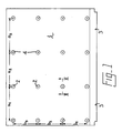
- Figure 1 shows a plan view of the setting-up plate,
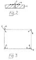
- Figure 2 shows a section along line II-II of Figure 1, and,
- Figure 3 illustrates the method of calculating the correction for any point on the table.
- The preferred method is used for setting-up a component placement machine to account for errors in the X-Y table drive thereof. The machine comprises a CCD camera (not shown) looking downwards at the X-Y table and having a reference point at the centre of its two dimensional field of view. Conveniently, the CCD camera used may be that normally present in some machines for detecting location marks of printed circuits on a printed circuit board. A setting-up plate (1) is mounted in an accurately known position on the X-Y table by means of aligning location points (3) of the X-Y table and the setting-up plate.
- The plate (1) comprises an aluminium plate on which are mounted sixteen pins (2) in a four by four array. The distances a₁, a₂, a₃ etc. between adjacent pins in the x-direction are nominally the same and the distances b₁, b₂, b₃ etc. between adjacent pins in the y-direction, are also nominally the same though not necessarily the same as the inter-pin distances in the x-direction, and are measured accurately for every inter-pin distance by known means.
- The temperature at which these measurements are carried out is recorded and is marked on the plate. When the plate is subsequently used in the preferred method in the setting-up of a component placement machine, the setting up is carried out at a temperature within about 5°C of the measuring temperature in order substantially to obviate any error due to thermal expansion or contraction of the setting-up plate.
- The area of the plate (1) covered by the array of pins (2) is substantially equal to the effective working area of the X-Y table, that is the area on which components are to be placed, on a substrate which is to be mounted on the table. The pins are drilled into the plate to ensure secure fixing, and each pin may be provided with a collar (4), suitably of black rubber, to give a dark background to the pin to assist detection by the camera.
- To carry out the preferred method the control system of the X-Y table is informed of the x,y coordinates of each of the pins on the setting-up plate mounted on the X-Y table, and the X-Y table is driven by means of its control system to the position where the reference point of the CCD camera is expected to coincide with a first pin i.e. the drive attempts to position the table so that the reference point of the camera is at the known x-y coordinates of the first pin.
- The actual position of the pin relative to the reference point is detected using the CCD camera, and the x and y distances between the actual position and said reference point are determined by counting the number of pixels in the field of view of the camera between the detected actual position and the reference point. Thus, the error at the pin is determined.
- The X-Y table is then driven by means of its control system to the position where the reference point of the CCD camera is expected to coincide with the known x,y coordinates of a second pin, and the steps of detection, and determining distances are repeated for this pin.
- This process is repeated in turn until the error in the X-Y table drive has been calculated for each pin position.
- In order to check that the errors have been correctly calculated and recorded, the X-Y table is then driven under its control system to each pin position, applying a correction which takes account of the errors determined, and the CCD camera is used to check that the actual position of each pin is within acceptably small x and y distances from the reference point. If not, the method is repeated for that pin.
- The setting-up plate is then removed from the X-Y table, and the component placement machine can be used for the placing of components on a substrate. In order to explain more clearly how the measurements taken in the setting-up process can be used in the control system of the X-Y table to correct for errors, an example of the calculation required will now be given, with particular reference to Figure 3 of the accompanying drawings, in which any four adjacent pins a, b, c and d of the array are shown at known coordinates ax, ay ; bx, by ; cx, cy ; and dx, dy. These pins were detected at A, B, C and D and found to have coordinates of Ax, Ay ; Bx, By ; Cx, Cy ; and Dx, Dy, Ax being ax plus the x error detected at a, and so on.
- When scaling generally along the x axis between points C and D the x axis scaling factor is given by
(Dx - Cx)/(dx - cx)
and this is multiplied by x to give the corrected value X at any point along the line between c and d. - Thus, X = ((Dx - Cx)/(dx - cx)) x
or X = x ± (((Dx - Cx)/(dx - cx))- 1) x
or X = x ± (Dx - Cx - dx ± cx) x/(dx - cx).
so that the scaling factor K = (Dx - Cx - dx ± cx)/(dx - cx). - Similarity scaling between points A and B along the x axis gives a scaling factor L = (Bx - Ax - bx ± ax)/(bx - ax).
- Now considering variable x scaling depending on y, this is given by X = x ± Lx (y/(ay - cy)) ± Kx (1-(y/(ay - cy)))
or X = x ± Lx (y/(ay - cy)) ± Kx - Kx (y/(ay - cy))
or X = x ± Kx ± ((Lx - Kx)/(ay - cy)) y
or X = x ± Kx ± Mxy, where
M = (L - K)/(ay - cy) - If point c is taken as a reference, i.e. (0,0), for any value of y if x=0 then the scaling is also 0, therefore, any x displacement is due to axis skew.
- Axis skew on line c to a is
((Ax - Cx) - (ax - cx))/(ay - cy)
X = ((Ax - Cx - ax ± cx)/(ay - cy)) y
X = Ny where N = (Ax - Cx - ax ± cx)/(ay - cy).
So the total correction is given by X = x ± Kx ± Mxy ± Ny and hence this is the algorithm calculated for the x drive correction for driving to any point within the rectangular area bounded by a, b, c and d which is based on the coordinates of a, b, c and d and cf A, B, C and D. - By a similar calculation on the y axis,
Y = y ± Py ± Sxy ± Tx, which is the algorithm for y drive correction
where P = (Ay - Cy - ay ± cy)/(ay - cy)
S = (R - P)/(dx - cx) where R = (By - Dy - by ± dy)/(by - dy)
and T = (Dy - Cy - dy ± cy)/(dx - cx).
Claims (9)
Applications Claiming Priority (4)
| Application Number | Priority Date | Filing Date | Title |
|---|---|---|---|
| GB888801896A GB8801896D0 (en) | 1988-01-28 | 1988-01-28 | Method of setting-up apparatus for handling electrical/electronic components |
| GB8801896 | 1988-01-28 | ||
| GB8811253 | 1988-05-12 | ||
| GB888811253A GB8811253D0 (en) | 1988-05-12 | 1988-05-12 | Method of setting up apparatus for handling electrical components |
Publications (2)
| Publication Number | Publication Date |
|---|---|
| EP0326236A2 true EP0326236A2 (en) | 1989-08-02 |
| EP0326236A3 EP0326236A3 (en) | 1990-08-16 |
Family
ID=26293378
Family Applications (1)
| Application Number | Title | Priority Date | Filing Date |
|---|---|---|---|
| EP89300030A Ceased EP0326236A3 (en) | 1988-01-28 | 1989-01-04 | Method of setting up apparatus for handling electrical or electronic components |
Country Status (5)
| Country | Link |
|---|---|
| US (1) | US4999764A (en) |
| EP (1) | EP0326236A3 (en) |
| JP (1) | JPH01227499A (en) |
| KR (1) | KR890012521A (en) |
| MY (1) | MY103662A (en) |
Cited By (7)
| Publication number | Priority date | Publication date | Assignee | Title |
|---|---|---|---|---|
| FR2741505A1 (en) * | 1995-11-20 | 1997-05-23 | Magneti Marelli France | Electronic substrate for formation of circuit board |
| WO2000015016A2 (en) * | 1998-09-02 | 2000-03-16 | Siemens Production And Logistics Systems Ag | Method and device for calibrating a displacement path and/or angular position of a holding device in a device for producing electrical assembly groups and calibration substrate |
| WO2003105557A1 (en) * | 2002-06-05 | 2003-12-18 | Siemens Aktiengesellschaft | Method for measuring the deformation of a flat positioning device |
| WO2006061201A1 (en) * | 2004-12-08 | 2006-06-15 | Multiline International Europa L.P | Method for registering workpieces and detection system for registering the analysis |
| WO2008121068A1 (en) * | 2007-03-30 | 2008-10-09 | Mydata Automation Ab | Arrangement and system at a component mounting machine |
| WO2008121061A1 (en) * | 2007-03-30 | 2008-10-09 | Mydata Automation Ab | A component magazine for a component mounting machine |
| EP3346812A4 (en) * | 2015-09-04 | 2018-07-11 | Fuji Machine Mfg. Co., Ltd. | Operation machine |
Families Citing this family (14)
| Publication number | Priority date | Publication date | Assignee | Title |
|---|---|---|---|---|
| JP2621416B2 (en) * | 1988-09-22 | 1997-06-18 | 松下電器産業株式会社 | Plate for measuring travel distance |
| JP2683489B2 (en) * | 1993-08-11 | 1997-11-26 | インターナショナル・ビジネス・マシーンズ・コーポレイション | Data transfer control device |
| US6205364B1 (en) | 1999-02-02 | 2001-03-20 | Creo Ltd. | Method and apparatus for registration control during processing of a workpiece particularly during producing images on substrates in preparing printed circuit boards |
| US6710798B1 (en) * | 1999-03-09 | 2004-03-23 | Applied Precision Llc | Methods and apparatus for determining the relative positions of probe tips on a printed circuit board probe card |
| US6593066B2 (en) | 2001-02-28 | 2003-07-15 | Creo Il. Ltd. | Method and apparatus for printing patterns on substrates |
| US6493064B2 (en) | 2001-02-28 | 2002-12-10 | Creo Il, Ltd. | Method and apparatus for registration control in production by imaging |
| JP4839535B2 (en) * | 2001-07-13 | 2011-12-21 | ソニー株式会社 | Coordinate correction method, coordinate correction apparatus, and reference correction jig |
| DE10300518B4 (en) * | 2003-01-09 | 2005-06-23 | Siemens Ag | Device for loading substrates with components and method for calibrating such a device |
| JP2008166410A (en) * | 2006-12-27 | 2008-07-17 | Toray Eng Co Ltd | Positioning calibration method, and mounting device applying the same |
| US8040530B2 (en) * | 2007-08-23 | 2011-10-18 | 3D Systems, Inc. | Automatic geometric calibration using laser scanning reflectometry |
| JP2011191307A (en) * | 2011-03-25 | 2011-09-29 | Sony Corp | Correction tool |
| CN104602872B (en) * | 2012-09-04 | 2017-03-08 | 富士机械制造株式会社 | Apparatus for work |
| JP6985814B2 (en) * | 2017-05-09 | 2021-12-22 | 株式会社Fuji | Board work machine |
| WO2019244264A1 (en) * | 2018-06-20 | 2019-12-26 | 株式会社Fuji | Control method, electronic component mounting device, and correction substrate |
Citations (4)
| Publication number | Priority date | Publication date | Assignee | Title |
|---|---|---|---|---|
| GB1142774A (en) * | 1967-04-17 | 1969-02-12 | Gerber Scientific Instr Co | Error correcting system for use with plotters, machine tools and the like |
| WO1985003368A1 (en) * | 1984-01-20 | 1985-08-01 | Mydata Automation Ab | Method and apparatus for calibrating a positioning system |
| WO1985003404A1 (en) * | 1984-01-23 | 1985-08-01 | Dyna/Pert - Precima Limited | Head for handling electrical components |
| US4651203A (en) * | 1985-10-29 | 1987-03-17 | At&T Technologies, Inc. | Video controlled article positioning system |
Family Cites Families (5)
| Publication number | Priority date | Publication date | Assignee | Title |
|---|---|---|---|---|
| US3988535A (en) * | 1975-11-04 | 1976-10-26 | Western Electric Company, Inc. | Automated positioning |
| US4233625A (en) * | 1978-11-03 | 1980-11-11 | Teledyne, Inc. | Television monitoring system for automatically aligning semiconductor devices during manufacture |
| FR2451796A1 (en) * | 1979-03-22 | 1980-10-17 | Cit Alcatel | LASER CUTTING METHOD AND APPARATUS FOR IMPLEMENTING THE METHOD |
| US4342090A (en) * | 1980-06-27 | 1982-07-27 | International Business Machines Corp. | Batch chip placement system |
| JPS57204127A (en) * | 1981-06-10 | 1982-12-14 | Hitachi Ltd | Drawing method for pattern of electron-ray drawing device |
-
1988
- 1988-12-21 MY MYPI88001492A patent/MY103662A/en unknown
-
1989
- 1989-01-04 EP EP89300030A patent/EP0326236A3/en not_active Ceased
- 1989-01-11 US US07/295,968 patent/US4999764A/en not_active Expired - Fee Related
- 1989-01-25 JP JP1016071A patent/JPH01227499A/en active Pending
- 1989-01-27 KR KR1019890000880A patent/KR890012521A/en not_active Application Discontinuation
Patent Citations (4)
| Publication number | Priority date | Publication date | Assignee | Title |
|---|---|---|---|---|
| GB1142774A (en) * | 1967-04-17 | 1969-02-12 | Gerber Scientific Instr Co | Error correcting system for use with plotters, machine tools and the like |
| WO1985003368A1 (en) * | 1984-01-20 | 1985-08-01 | Mydata Automation Ab | Method and apparatus for calibrating a positioning system |
| WO1985003404A1 (en) * | 1984-01-23 | 1985-08-01 | Dyna/Pert - Precima Limited | Head for handling electrical components |
| US4651203A (en) * | 1985-10-29 | 1987-03-17 | At&T Technologies, Inc. | Video controlled article positioning system |
Cited By (9)
| Publication number | Priority date | Publication date | Assignee | Title |
|---|---|---|---|---|
| FR2741505A1 (en) * | 1995-11-20 | 1997-05-23 | Magneti Marelli France | Electronic substrate for formation of circuit board |
| WO2000015016A2 (en) * | 1998-09-02 | 2000-03-16 | Siemens Production And Logistics Systems Ag | Method and device for calibrating a displacement path and/or angular position of a holding device in a device for producing electrical assembly groups and calibration substrate |
| WO2000015016A3 (en) * | 1998-09-02 | 2000-06-02 | Siemens Ag | Method and device for calibrating a displacement path and/or angular position of a holding device in a device for producing electrical assembly groups and calibration substrate |
| WO2003105557A1 (en) * | 2002-06-05 | 2003-12-18 | Siemens Aktiengesellschaft | Method for measuring the deformation of a flat positioning device |
| WO2006061201A1 (en) * | 2004-12-08 | 2006-06-15 | Multiline International Europa L.P | Method for registering workpieces and detection system for registering the analysis |
| WO2008121068A1 (en) * | 2007-03-30 | 2008-10-09 | Mydata Automation Ab | Arrangement and system at a component mounting machine |
| WO2008121061A1 (en) * | 2007-03-30 | 2008-10-09 | Mydata Automation Ab | A component magazine for a component mounting machine |
| US8234779B2 (en) | 2007-03-30 | 2012-08-07 | Mydata Automation Ab | Arrangement and system at a component mounting machine |
| EP3346812A4 (en) * | 2015-09-04 | 2018-07-11 | Fuji Machine Mfg. Co., Ltd. | Operation machine |
Also Published As
| Publication number | Publication date |
|---|---|
| US4999764A (en) | 1991-03-12 |
| EP0326236A3 (en) | 1990-08-16 |
| MY103662A (en) | 1993-08-28 |
| KR890012521A (en) | 1989-08-26 |
| JPH01227499A (en) | 1989-09-11 |
Similar Documents
| Publication | Publication Date | Title |
|---|---|---|
| US4999764A (en) | Method of setting up apparatus for handling electrical or electronic components | |
| US7181089B2 (en) | Method and apparatus for searching for fiducial marks, and method of detecting positions of the fiducial marks | |
| EP1331840B1 (en) | Method of locating and placing eye point features of a semiconductor die on a substrate | |
| US5749142A (en) | Method and device for adjusting nozzle height for recognition in surface mounter | |
| JP4426585B2 (en) | Pick and place machine with image acquisition device | |
| JP3500124B2 (en) | Method and apparatus for calibrating a moving distance and / or an angular position of a holding device provided in a manufacturing apparatus of an electrical component group, and a calibration substrate | |
| JPH01127238A (en) | Improvement in positional feedback in limiting re-positioning region for movable member | |
| US4922434A (en) | Linear interpolation for a component placement robot | |
| KR20010074993A (en) | Method and device for processing substrates | |
| US6683688B1 (en) | Method and device for gauging a device for producing electrical components | |
| US5896652A (en) | Method of packaging electronic components | |
| JP4515814B2 (en) | Mounting accuracy measurement method | |
| EP0326235A2 (en) | Method of setting up apparatus for handling electrical or electronic components | |
| KR102600201B1 (en) | Determining component height deviations | |
| JP3286105B2 (en) | Mounting position correction method for mounting machine | |
| KR20060002812A (en) | Method and device for aligning a substrate and a printing screen during solder paste printing | |
| CN113811178B (en) | Assembly machine for assembling electronic components on component carrier and method thereof | |
| EP3823428B1 (en) | Template creating device and component mounting machine | |
| JP2584779B2 (en) | Component mounting method | |
| JP2694462B2 (en) | Positioning method for semiconductor wafer chips | |
| JPH0761583B2 (en) | How to install chip parts | |
| JPH0738519B2 (en) | Electronic component mounting method | |
| JP2009170586A (en) | Method and apparatus for recognizing electronic component | |
| JP3615920B2 (en) | Electronic component mounting method | |
| JP2556383Y2 (en) | connector |
Legal Events
| Date | Code | Title | Description |
|---|---|---|---|
| PUAI | Public reference made under article 153(3) epc to a published international application that has entered the european phase |
Free format text: ORIGINAL CODE: 0009012 |
|
| AK | Designated contracting states |
Kind code of ref document: A2 Designated state(s): BE CH DE FR GB IT LI NL SE |
|
| RAP1 | Party data changed (applicant data changed or rights of an application transferred) |
Owner name: DYNAPERT LIMITED Owner name: EMHART INDUSTRIES, INC. |
|
| RAP1 | Party data changed (applicant data changed or rights of an application transferred) |
Owner name: DYNAPERT INC. Owner name: EMHART INDUSTRIES, INC. |
|
| PUAL | Search report despatched |
Free format text: ORIGINAL CODE: 0009013 |
|
| RHK1 | Main classification (correction) |
Ipc: H05K 13/08 |
|
| AK | Designated contracting states |
Kind code of ref document: A3 Designated state(s): BE CH DE FR GB IT LI NL SE |
|
| 17P | Request for examination filed |
Effective date: 19901027 |
|
| RAP1 | Party data changed (applicant data changed or rights of an application transferred) |
Owner name: DYNAPERT INC. Owner name: DYNAPERT LIMITED |
|
| RAP1 | Party data changed (applicant data changed or rights of an application transferred) |
Owner name: DYNAPERT LIMITED Owner name: EMHART INC. |
|
| 17Q | First examination report despatched |
Effective date: 19930712 |
|
| STAA | Information on the status of an ep patent application or granted ep patent |
Free format text: STATUS: THE APPLICATION HAS BEEN REFUSED |
|
| 18R | Application refused |
Effective date: 19940121 |