EP0323618B1 - Line pressure control system for automatic transmission - Google Patents
Line pressure control system for automatic transmission Download PDFInfo
- Publication number
- EP0323618B1 EP0323618B1 EP88121587A EP88121587A EP0323618B1 EP 0323618 B1 EP0323618 B1 EP 0323618B1 EP 88121587 A EP88121587 A EP 88121587A EP 88121587 A EP88121587 A EP 88121587A EP 0323618 B1 EP0323618 B1 EP 0323618B1
- Authority
- EP
- European Patent Office
- Prior art keywords
- line pressure
- shifting
- shift
- duty
- automatic transmission
- Prior art date
- Legal status (The legal status is an assumption and is not a legal conclusion. Google has not performed a legal analysis and makes no representation as to the accuracy of the status listed.)
- Expired - Lifetime
Links
Images


Classifications
-
- F—MECHANICAL ENGINEERING; LIGHTING; HEATING; WEAPONS; BLASTING
- F16—ENGINEERING ELEMENTS AND UNITS; GENERAL MEASURES FOR PRODUCING AND MAINTAINING EFFECTIVE FUNCTIONING OF MACHINES OR INSTALLATIONS; THERMAL INSULATION IN GENERAL
- F16H—GEARING
- F16H61/00—Control functions within control units of change-speed- or reversing-gearings for conveying rotary motion ; Control of exclusively fluid gearing, friction gearing, gearings with endless flexible members or other particular types of gearing
- F16H61/04—Smoothing ratio shift
- F16H61/0437—Smoothing ratio shift by using electrical signals
-
- F—MECHANICAL ENGINEERING; LIGHTING; HEATING; WEAPONS; BLASTING
- F16—ENGINEERING ELEMENTS AND UNITS; GENERAL MEASURES FOR PRODUCING AND MAINTAINING EFFECTIVE FUNCTIONING OF MACHINES OR INSTALLATIONS; THERMAL INSULATION IN GENERAL
- F16H—GEARING
- F16H61/00—Control functions within control units of change-speed- or reversing-gearings for conveying rotary motion ; Control of exclusively fluid gearing, friction gearing, gearings with endless flexible members or other particular types of gearing
- F16H61/0021—Generation or control of line pressure
-
- F—MECHANICAL ENGINEERING; LIGHTING; HEATING; WEAPONS; BLASTING
- F16—ENGINEERING ELEMENTS AND UNITS; GENERAL MEASURES FOR PRODUCING AND MAINTAINING EFFECTIVE FUNCTIONING OF MACHINES OR INSTALLATIONS; THERMAL INSULATION IN GENERAL
- F16H—GEARING
- F16H61/00—Control functions within control units of change-speed- or reversing-gearings for conveying rotary motion ; Control of exclusively fluid gearing, friction gearing, gearings with endless flexible members or other particular types of gearing
- F16H2061/0075—Control functions within control units of change-speed- or reversing-gearings for conveying rotary motion ; Control of exclusively fluid gearing, friction gearing, gearings with endless flexible members or other particular types of gearing characterised by a particular control method
- F16H2061/0087—Adaptive control, e.g. the control parameters adapted by learning
-
- F—MECHANICAL ENGINEERING; LIGHTING; HEATING; WEAPONS; BLASTING
- F16—ENGINEERING ELEMENTS AND UNITS; GENERAL MEASURES FOR PRODUCING AND MAINTAINING EFFECTIVE FUNCTIONING OF MACHINES OR INSTALLATIONS; THERMAL INSULATION IN GENERAL
- F16H—GEARING
- F16H61/00—Control functions within control units of change-speed- or reversing-gearings for conveying rotary motion ; Control of exclusively fluid gearing, friction gearing, gearings with endless flexible members or other particular types of gearing
- F16H2061/0075—Control functions within control units of change-speed- or reversing-gearings for conveying rotary motion ; Control of exclusively fluid gearing, friction gearing, gearings with endless flexible members or other particular types of gearing characterised by a particular control method
- F16H2061/0096—Control functions within control units of change-speed- or reversing-gearings for conveying rotary motion ; Control of exclusively fluid gearing, friction gearing, gearings with endless flexible members or other particular types of gearing characterised by a particular control method using a parameter map
-
- F—MECHANICAL ENGINEERING; LIGHTING; HEATING; WEAPONS; BLASTING
- F16—ENGINEERING ELEMENTS AND UNITS; GENERAL MEASURES FOR PRODUCING AND MAINTAINING EFFECTIVE FUNCTIONING OF MACHINES OR INSTALLATIONS; THERMAL INSULATION IN GENERAL
- F16H—GEARING
- F16H61/00—Control functions within control units of change-speed- or reversing-gearings for conveying rotary motion ; Control of exclusively fluid gearing, friction gearing, gearings with endless flexible members or other particular types of gearing
- F16H61/02—Control functions within control units of change-speed- or reversing-gearings for conveying rotary motion ; Control of exclusively fluid gearing, friction gearing, gearings with endless flexible members or other particular types of gearing characterised by the signals used
- F16H61/0202—Control functions within control units of change-speed- or reversing-gearings for conveying rotary motion ; Control of exclusively fluid gearing, friction gearing, gearings with endless flexible members or other particular types of gearing characterised by the signals used the signals being electric
- F16H61/0251—Elements specially adapted for electric control units, e.g. valves for converting electrical signals to fluid signals
- F16H2061/0255—Solenoid valve using PWM or duty-cycle control
-
- F—MECHANICAL ENGINEERING; LIGHTING; HEATING; WEAPONS; BLASTING
- F16—ENGINEERING ELEMENTS AND UNITS; GENERAL MEASURES FOR PRODUCING AND MAINTAINING EFFECTIVE FUNCTIONING OF MACHINES OR INSTALLATIONS; THERMAL INSULATION IN GENERAL
- F16H—GEARING
- F16H61/00—Control functions within control units of change-speed- or reversing-gearings for conveying rotary motion ; Control of exclusively fluid gearing, friction gearing, gearings with endless flexible members or other particular types of gearing
- F16H61/68—Control functions within control units of change-speed- or reversing-gearings for conveying rotary motion ; Control of exclusively fluid gearing, friction gearing, gearings with endless flexible members or other particular types of gearing specially adapted for stepped gearings
- F16H61/684—Control functions within control units of change-speed- or reversing-gearings for conveying rotary motion ; Control of exclusively fluid gearing, friction gearing, gearings with endless flexible members or other particular types of gearing specially adapted for stepped gearings without interruption of drive
Definitions
- the present invention relates to a line pressure control system for an automatic transmission, and more particularly to a system for controlling line pressure when the automatic transmission is shifting between two gear ratios.
- a desired gear ratio is established by hydraulically activating selected one or ones of various friction devices (such as clutches and brakes) by line pressure, and a shift between two gear ratios is effected by changing friction device or devices to be activated.
- various friction devices such as clutches and brakes
- the line pressure has to be appropriately controlled.
- a drain circuit of a line pressure regulator valve is opened or closed by a line pressure solenoid of the duty cycle type. The duty varies from 0 % to 100 %.
- the line pressure solenoid When the duty is 0 %, the line pressure solenoid is left OFF, closing the drain circuit, while when the duty is 100 %, the line pressure solenoid is left ON, opening the drain Circuit.
- increasing the duty causes the line pressure regulator to increase a magnitude of a line pressure generated thereby.
- Various values of the duty are contained in a table data in a ROM of a microcomputer of an automatic transmission control unit. Different table data are provided, one for use at shifting operation, another for normal stable non-shifting operation, for example.
- the duty values are arranged in each table data as being retrieveable by table lock-up operation using a variable such as a throttle opening degree.
- this conventional line pressure control system cannot cope with a situation where the line pressure solenoid has a manufacturing variation or the characteristic of the line pressure solenoid degrades with time or a situation where the friction device has a manufacturing variation or the frictional material of the friction device degrades with time.
- the magnitude of line pressure deviates from a target value.
- the friction device does not show a desired performance characteristic.
- the conventional line pressure control system fails to avoid occurrence of substantial shift shock or reduction in operating life of the friction device.
- a line pressure control system for an automatic transmission comprising sensor means for detecting input and output speeds of the transmission.
- sensor means for detecting input and output speeds of the transmission.
- an instantaneous ratio of input and output speeds are calculated.
- the line pressure is regulated in a closed loop control so that the instantaneous ratio follows a predetermined curve.
- An object of the present invention is to provide a line pressure control system for an automatic transmission wherein a magnitude of line pressure is adjusted always to such an appropriate value as to cope with the above-mentioned situations.
- an inertia phase time is measured in response to an input/output speed ratio of an automatic transmission, and a line pressure acting on a shifting friction device is adjusted in such a direction as to bring an inertia phase time during a shift into agreement with a predetermined value.
- a line pressure control system for an automatic transmission including a transmission input member and a transmission output member, the automatic transmission being shiftable between two gear ratios and including a friction device whcih is adpated to be engaged in response to a magnitude of a line pressure to effect a shifting between the two gear ratios
- the line pressure control system comprising: input sensor means for detecting a revolution speed of the transmission input member and generating a first sensor output signal indicative of said revolution speed of the transmission input member detected; output sensor means for detecting a revolution speed of the transmission output member and generating a second sensor output signal indicative of said revolution speed of the transmission output member detected; means responsive to said first and second sensor output signals for determining a gear ratio of said revolution speed of the transmission input member to said revolution speed of the transmission output member; means for measuring an inertia phase time when said gear ratio varies within a predetermined range during the shifting; means for adjusting the magnitude of the line pressure which the friction device is engaged on during the next occurrence of the shifting in such a
- the present invention is based on a recognition that an inertia phase time during which a gear ratio varies becomes long when a line pressure applied to a shifting friction device is excessively high, whereas it becomes short when the line pressure is excessively low, and thus it can be evaluated whether the magnitude of the line pressure is appropriate or not based on evaluation of the inertia phase time measured.
- the total time elapsed from the beginning of the shift to the completion thereof and the inertia phase period of time are measured and, if after the completion of the shift, said total time is less than a first predetermined value, the line pressure reference data are adjusted in response to a deviation of the determined inertia period from a second predetermined value, such that the magnitude of the line pressure is corrected during the next shifting.
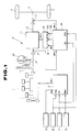
- Fig. 1 shows a power train control system incorporating a line pressure control system according to the present invention.
- the reference numeral 1 designates an electronic fuel injection internal combustion engine, 2 an automatic transmission, 3 a differential gear, and 4 a pair of traction wheels.
- the engine 1 is provided with a microcomputer based engine control unit 5. Supplied to the control unit 5 are output signals of an engine revolution speed sensor 6 arranged to detect an engine revolution speed N E , a vehicle speed sensor 7 arranged to detect a vehicle speed V, a thorttle sensor 8 arranged to detect an engine throttle opening degree TH, and an intake air sensor 9 arranged to detect an amount ofan engine intake air Q.
- a width T P of a fuel injection pulse is determined based on various kinds of input information carried by these sensor output signals supplied.
- An ignition timing is determined also in the control unit 5.
- Output signals of the control unit 5 indicative of the pulse width T P and the ignition timing determined are supplied to the engine 1. Then, the engine 1 is supplied with an amount fuel corresponding to the fuel injection pulse width T P and operates on combustion of the fuel supplied.
- the automatic transmission 2 includes a torque converter 10 and a change-speed gearing mechanism 11 arranged in tandem.
- the engine drive is delivered to a transmission input shaft 12 via the torque converter 11.
- An input revolution speed of the input shaft 12 is delivered to a transmission output shaft 13.
- a revolution of the output shaft 13 is transmitted to the pair of traction wheels 4.
- the change-speed gearing mechanism 11 involves various friction devices, such as clutches and brakes, which are selectively activated by a line pressure P L to establish a desired transmission ratio. A shift between two gear ratios is effected by changing the friction device or devices to be activated.
- the control valve assembly 15 includes a shift solenoid 15a and a shift solenoid 15b. These shift solenoids 15a and 15b are selectively energized and thus rendered ON. In response to various combinations of ON state and OFF state of these shift solenoids 15a and 15b, the line pressure P L is supplied to the various friction devices, selectively, to establish a gear ratio corresponding to an ON/OFF combination selected.
- the control valve assembly 15 also includes a duty solenoid 16 for controlling the line pressure P L .
- This duty solenoid 16 is activated in accordance with a drive duty D supplied thereto and increases the magnitude of line pressure P L in response to an increase in the drive duty D.
- Supplied to the control unit 14 are output signals of the vehicle speed sensor 7, the throttle sensor 8, an input revolution speed sensor 17 arranged to detect a revolution speed N T of the input shaft 12, and an output revolution speed sensor 18 arranged to detect a revolution speed N O of the output shaft 13.
- the control unit 14 includes ROM (Read Only Memory) which stores control programs illustrated by the flowcharts shown in Figs. 2 to 4 and effects the line pressure control and ratio change control.
- ROM Read Only Memory
- the transmission 2 including the change-speed gearing mechanism 11 and the control valve assembly 15 with two shift solenoids 15a and 15b and line pressure solenoid 16 as well known and described in detail in the before mentioned publication entitled "SERVICE MANUAL FOR AUTOMATIC TRANSMISSION OF THE RE4R01A TYPE" (A261C07) published in March 1987 by NISSAN MOTOR COMPANY, LIMITED.
- A261C07 published in March 1987 by NISSAN MOTOR COMPANY, LIMITED.
- United States Patent US-A-4,680,992 issued to Hayasaki et al.on July. 21, 1987, (see shift solenoids 42 and 44, and a line pressure solenoid 24 in FIGS. 1A, 1B and 1C).
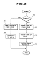
- Fig. 2 shows the line pressure control.
- the execution of this line pressure control is initiated by a timer interruption.
- a step 20 it is checked whether a flag FLAG1 is equal to 1 or not.
- the FLAG1 is equal to 1 when the change-speed gearing mechanism 11 is shifting, while the FLAG1 is not equal to 1 when it is not shifting.
- the control proceeds from the step 20 to a step 21 where a table look-up operation is performed using a throttle opening degree TH to obtain a duty D which the line pressure solenoid 16 is subject to from a table data for non-shifting as illustrated by a fully drawn characteristic curve A in Fig. 5, which duty D corresponds to the throttle opening degree TH.
- this duty D obtained at the step 21 is outputted to the line pressure solenoid 16.
- the line pressure P L is adjusted to an appropriate value for non-shifting operation.
- step 23 When the change-speed gearing mechanism 11 is shifting, the answer to the enquiry made at the step 20 is YES and the control proceeds to a step 23.
- step 23 there is performed a table look-up operation of a table data as illustrated by broken line drawn curve B in Fig. 5 using the throttle opening degree TH to obtain a duty D for line pressure control, which duty D corresponds to the throttle opening degree TH.
- a table look-up operation of a table data shwon in Fig. 5 is performed using the throttle opening degree TH to obtain a duty correction value ⁇ D (delta D) corresponding to the throttle opening degree TH.
- ⁇ D delta D
- Fig. 3 shows a control program for effecting a ratio change control and a line pressure solenoid duty correction value control. The execution of this control program is initiated by a time interruption.
- a step 30 it is checked whether the flag FLAG1 is equal to 1 or not. If the change-speed gearing mechanism 11 is not shifting and thus the flag FLAG1 is not equal to 1, the control proceeds from the step 30 to a step 31.
- a desired speed ratio is determined which corresponds to vehicle speed V and throttle opening degree TH. Then, the control proceeds to a step 32 where it is judged whether a shifting is needed or not based on whether a current gear ratio is the same as the required gear ratio determined at the step 31 or not.
- step 33 the flag FLAG1 is set equal to 1 and an ON-OFF combination of the shift solenoids 15a and 15b is changed to establish the required gear ratio in the change-speed gearing mechanism 11.
- the steps 31, 32 and 33 are skipped as long as the flag FLAG1 continues to be equal to 1.
- an increment is made to a timer T1.
- the control proceeds to a step 35 where it is checked whether an actual gear ratio N T /N O falls in a predetermined range determined in view of a gear ratio before the shifting and a gear ratio upon completion of the shift or not.
- the inertia phase proceeds when the answer to the enquiry at the step 35 is YES. If the answer to the enquiry at the step 35 is YES, the control proceeds to a step 36 where an increment is made to a timer T2.
- the control proceeds from the step 35 to a step 37 bypassing the step 36. If will now be noted that the content of the timer T2 represents a period of time when the intertia phase proceeds, viz., an intertia phase time.
- step 37 it is checked whether the inertia phase is completed or not.
- This step is cooperating with the step 35 such that the answer to the enquiry at the step 37 becomes NO when the answer to the enquiry at the step 35 is YES, while the answer to the enquiry at the step 37 becomes YES when the answer to the enquiry at the step 35 is NO.
- the control proceeds from the step 37 to a step 38 where the flag FLAG1 is reset to 0 (zero) and a flag FLAG2 is set equal to 1. This flag FLAG2 indicates whether a learning control which will be later described is to be executed or not.
- Fig. 4 shows the execution of this program.
- Fig. 4 at a step 50, it is checked whether the timer T1 is greater than a predetermined value T 1S .
- Fig. 7 shows the relationship between the content of the time T1 and the duty D + ⁇ D % during shifting and the relationship T2 and the duty D + ⁇ D % during shifting, respectively.
- ⁇ alpha
- the solenoid drive duty D + ⁇ D % takes an excessively small value, for example ⁇ (alpha)
- the timer value T1 is greater than or equal to a predetermined value T 1S
- the magnitude of line pressure is very low so that a shift with substantially great shock will take place as shown by broken lines ⁇ (alpha) in Fig. 8.
- the control proceeds from the step 50 to a step 52 where the inertia phase time T2 is checked. If the inertia phase time T2 is equal to a target value where the appropriate magnitude of line pressure is provided, the RAM data containing various correction values ⁇ D (delta D) shown in Fig. 6 are not modified. Thus, the current RAM data are used for the line pressure control for a shifting which is to take place next time.
- the target value T 2S mentioned above differs from one kind of shifting to another and it differs depending on the degree of throttle opening even with the same kind of shifting.
- the control proceeds from the step 52 to a step 53 where the correction value ⁇ D (delta D) in the RAM data is increased by 0.1 %.
- the magnitude of line pressure during the next shifting will be increased in accordance with this increase since the drive duty D + ⁇ D will be increased.
- the control proceeds from the step 52 to a step 54 since in this situation the line pressure is excessively high so that the engagement capacity of the friction device becomes excessively large to result in producing substantially great shock.
- the correction value ⁇ D (delta D) at the RAM data is decreased by 0.1 % and used for the next shifting. Therefore, the magnitude of line pressure is decreased during the next shifting, preventing the occurrence of shift shock.
- the magnitude of line pressure is kept at the most appropriate value by correcting data which the magnitude of line pressure is determined on by learning wherein the data is corrected in such a direction as to hold the inertia phase time T2 at the predetermined value T 2S .
Description
- The present invention relates to a line pressure control system for an automatic transmission, and more particularly to a system for controlling line pressure when the automatic transmission is shifting between two gear ratios.
- In the automatic transmissions, a desired gear ratio is established by hydraulically activating selected one or ones of various friction devices (such as clutches and brakes) by line pressure, and a shift between two gear ratios is effected by changing friction device or devices to be activated.
- If the line pressure is excessively high, transient engagement capacity of a friction device becomes excessively high, causing great shock to occur, whereas if the line pressure is excessively low, the transient engagement capacity of the friction device becomes excessively low, causing a slip to occur, thus shortening an operating life of the friction device. Thus, the line pressure has to be appropriately controlled. Conventionally, as described in the publication entitled "SERVICE MANUAL FOR AUTOMATIC TRANSMISSION OF THE RE4R01A TYPE" (A261C07) published by in March 1987 by NISSAN MOTOR COMPANY, LIMITED, a drain circuit of a line pressure regulator valve is opened or closed by a line pressure solenoid of the duty cycle type. The duty varies from 0 % to 100 %. When the duty is 0 %, the line pressure solenoid is left OFF, closing the drain circuit, while when the duty is 100 %, the line pressure solenoid is left ON, opening the drain Circuit. Thus, increasing the duty causes the line pressure regulator to increase a magnitude of a line pressure generated thereby. Various values of the duty are contained in a table data in a ROM of a microcomputer of an automatic transmission control unit. Different table data are provided, one for use at shifting operation, another for normal stable non-shifting operation, for example. The duty values are arranged in each table data as being retrieveable by table lock-up operation using a variable such as a throttle opening degree.
- However, this conventional line pressure control system cannot cope with a situation where the line pressure solenoid has a manufacturing variation or the characteristic of the line pressure solenoid degrades with time or a situation where the friction device has a manufacturing variation or the frictional material of the friction device degrades with time. In the former situation, even if the line pressure solenoid is subject to the same duty, the magnitude of line pressure deviates from a target value. In the latter situation, even if the magnitude of line pressure is adjusted to the target value, the friction device does not show a desired performance characteristic. Thus, in any event, the conventional line pressure control system fails to avoid occurrence of substantial shift shock or reduction in operating life of the friction device.
- From DE-A-32 05 767 a line pressure control system for an automatic transmission is known comprising sensor means for detecting input and output speeds of the transmission. In order to determine the inertia period of a shift an instantaneous ratio of input and output speeds are calculated. The line pressure is regulated in a closed loop control so that the instantaneous ratio follows a predetermined curve.
- An object of the present invention is to provide a line pressure control system for an automatic transmission wherein a magnitude of line pressure is adjusted always to such an appropriate value as to cope with the above-mentioned situations.
- According to the present invention, in order to cope with manufacturing variation or degradation with time, an inertia phase time is measured in response to an input/output speed ratio of an automatic transmission, and a line pressure acting on a shifting friction device is adjusted in such a direction as to bring an inertia phase time during a shift into agreement with a predetermined value.
- Specifically, there is provided a line pressure control system for an automatic transmission including a transmission input member and a transmission output member, the automatic transmission being shiftable between two gear ratios and including a friction device whcih is adpated to be engaged in response to a magnitude of a line pressure to effect a shifting between the two gear ratios, the line pressure control system, comprising:
input sensor means for detecting a revolution speed of the transmission input member and generating a first sensor output signal indicative of said revolution speed of the transmission input member detected;
output sensor means for detecting a revolution speed of the transmission output member and generating a second sensor output signal indicative of said revolution speed of the transmission output member detected;
means responsive to said first and second sensor output signals for determining a gear ratio of said revolution speed of the transmission input member to said revolution speed of the transmission output member;
means for measuring an inertia phase time when said gear ratio varies within a predetermined range during the shifting;
means for adjusting the magnitude of the line pressure which the friction device is engaged on during the next occurrence of the shifting in such a manner as to decrease a difference between said inertia phase time and a predetermined value. - The present invention is based on a recognition that an inertia phase time during which a gear ratio varies becomes long when a line pressure applied to a shifting friction device is excessively high, whereas it becomes short when the line pressure is excessively low, and thus it can be evaluated whether the magnitude of the line pressure is appropriate or not based on evaluation of the inertia phase time measured.
- The total time elapsed from the beginning of the shift to the completion thereof and the inertia phase period of time are measured and, if after the completion of the shift, said total time is less than a first predetermined value, the line pressure reference data are adjusted in response to a deviation of the determined inertia period from a second predetermined value, such that the magnitude of the line pressure is corrected during the next shifting.
-
- Fig. 1 is a block diagram of an automative power train incorporating a line pressure control system according to the present invention;
- Fig. 2 to 4 are flowcharts of a line pressure control program and a shift control program;
- Fig. 5 shows a characteristic of variation of duty ratio which a line pressure solenoid is subject to;
- Fig. 6 is a daigram illustrating duty correction values contained in a table data stored in a RAM;
- Fig. 7 shows variations of timer values versus various duty values; and
- Fig. 8 are time charts illustrating operation diagrams of a shift when different duty values α (alpha), β (betha), and γ (gamma) are used, respectively.
- Referring to the accompanying drawings, the present invention is described.
- Fig. 1 shows a power train control system incorporating a line pressure control system according to the present invention. In Fig. 1, the
reference numeral 1 designates an electronic fuel injection internal combustion engine, 2 an automatic transmission, 3 a differential gear, and 4 a pair of traction wheels. - The
engine 1 is provided with a microcomputer basedengine control unit 5. Supplied to thecontrol unit 5 are output signals of an enginerevolution speed sensor 6 arranged to detect an engine revolution speed NE, avehicle speed sensor 7 arranged to detect a vehicle speed V, athorttle sensor 8 arranged to detect an engine throttle opening degree TH, and anintake air sensor 9 arranged to detect an amount ofan engine intake air Q. In thecontrol unit 5, a width TP of a fuel injection pulse is determined based on various kinds of input information carried by these sensor output signals supplied. An ignition timing is determined also in thecontrol unit 5. Output signals of thecontrol unit 5 indicative of the pulse width TP and the ignition timing determined are supplied to theengine 1. Then, theengine 1 is supplied with an amount fuel corresponding to the fuel injection pulse width TP and operates on combustion of the fuel supplied. - The
automatic transmission 2 includes atorque converter 10 and a change-speed gearing mechanism 11 arranged in tandem. The engine drive is delivered to atransmission input shaft 12 via the torque converter 11. An input revolution speed of theinput shaft 12 is delivered to atransmission output shaft 13. A revolution of theoutput shaft 13 is transmitted to the pair of traction wheels 4. - The change-speed gearing mechanism 11 involves various friction devices, such as clutches and brakes, which are selectively activated by a line pressure PL to establish a desired transmission ratio. A shift between two gear ratios is effected by changing the friction device or devices to be activated.
- In order to control a gear ratio change in the change-speed gearing mechanism 11, a microcomputer based automatic
transmission control unit 14, and acontrol valve assembly 15 are provided. Thecontrol valve assembly 15 includes a shift solenoid 15a and ashift solenoid 15b. Theseshift solenoids 15a and 15b are selectively energized and thus rendered ON. In response to various combinations of ON state and OFF state of theseshift solenoids 15a and 15b, the line pressure PL is supplied to the various friction devices, selectively, to establish a gear ratio corresponding to an ON/OFF combination selected. Thecontrol valve assembly 15 also includes aduty solenoid 16 for controlling the line pressure PL. Thisduty solenoid 16 is activated in accordance with a drive duty D supplied thereto and increases the magnitude of line pressure PL in response to an increase in the drive duty D. Supplied to thecontrol unit 14 are output signals of thevehicle speed sensor 7, thethrottle sensor 8, an inputrevolution speed sensor 17 arranged to detect a revolution speed NT of theinput shaft 12, and an outputrevolution speed sensor 18 arranged to detect a revolution speed NO of theoutput shaft 13. - The
control unit 14 includes ROM (Read Only Memory) which stores control programs illustrated by the flowcharts shown in Figs. 2 to 4 and effects the line pressure control and ratio change control. - The
transmission 2 including the change-speed gearing mechanism 11 and thecontrol valve assembly 15 with twoshift solenoids 15a and 15b andline pressure solenoid 16 as well known and described in detail in the before mentioned publication entitled "SERVICE MANUAL FOR AUTOMATIC TRANSMISSION OF THE RE4R01A TYPE" (A261C07) published in March 1987 by NISSAN MOTOR COMPANY, LIMITED. In order to fully understood how a gear ratio change is carried out by the twoshift solenoids 15a and 15b and how the magnitude of line pressure is adjusted by theline pressure solenoid 16, reference should be made to United States Patent US-A-4,680,992, issued to Hayasaki et al.on July. 21, 1987, (see shift solenoids 42 and 44, and aline pressure solenoid 24 in FIGS. 1A, 1B and 1C). - Fig. 2 shows the line pressure control. The execution of this line pressure control is initiated by a timer interruption. In Fig. 2, at a
step 20, it is checked whether a flag FLAG1 is equal to 1 or not. The FLAG1 is equal to 1 when the change-speed gearing mechanism 11 is shifting, while the FLAG1 is not equal to 1 when it is not shifting. Thus, when the change-speed gearing mechanism 11 is not shifting, the control proceeds from thestep 20 to astep 21 where a table look-up operation is performed using a throttle opening degree TH to obtain a duty D which theline pressure solenoid 16 is subject to from a table data for non-shifting as illustrated by a fully drawn characteristic curve A in Fig. 5, which duty D corresponds to the throttle opening degree TH. Then, this duty D obtained at thestep 21 is outputted to theline pressure solenoid 16. As a result, the line pressure PL is adjusted to an appropriate value for non-shifting operation. - When the change-speed gearing mechanism 11 is shifting, the answer to the enquiry made at the
step 20 is YES and the control proceeds to astep 23. At thestep 23, there is performed a table look-up operation of a table data as illustrated by broken line drawn curve B in Fig. 5 using the throttle opening degree TH to obtain a duty D for line pressure control, which duty D corresponds to the throttle opening degree TH. At thesubsequent step 24, a table look-up operation of a table data shwon in Fig. 5 is performed using the throttle opening degree TH to obtain a duty correction value ΔD (delta D) corresponding to the throttle opening degree TH. The table data as illustrated in Fig. 6 are stored in a RAM (Random Acess Memory) of thecontrol unit 14 and contains various duty correction values which are updated after learning control which will be later described. Then, the control proceeds to astep 25 where a sum D + ΔD (delta D) is outputted to theline pressure solenoid 16. As a result, the line pressure PL is adjusted to the appropriate value for shifting operation. - Fig. 3 shows a control program for effecting a ratio change control and a line pressure solenoid duty correction value control. The execution of this control program is initiated by a time interruption. In Fig. 3, at a
step 30, it is checked whether the flag FLAG1 is equal to 1 or not. If the change-speed gearing mechanism 11 is not shifting and thus the flag FLAG1 is not equal to 1, the control proceeds from thestep 30 to astep 31. At thestep 31, using a predetermined shift schedule diagram, a desired speed ratio is determined which corresponds to vehicle speed V and throttle opening degree TH. Then, the control proceeds to astep 32 where it is judged whether a shifting is needed or not based on whether a current gear ratio is the same as the required gear ratio determined at thestep 31 or not. If a shift is needed and thus the answer to the enquiry at thestep 32 is YES, the control proceeds from thisstep 32 to astep 33. At thestep 33, the flag FLAG1 is set equal to 1 and an ON-OFF combination of theshift solenoids 15a and 15b is changed to establish the required gear ratio in the change-speed gearing mechanism 11. In the next and subsequent run, thesteps - At the
subsequent step 34, an increment is made to a timer T₁. Then, the control proceeds to astep 35 where it is checked whether an actual gear ratio NT/NO falls in a predetermined range determined in view of a gear ratio before the shifting and a gear ratio upon completion of the shift or not. In this case, it is recognized that the inertia phase proceeds when the answer to the enquiry at thestep 35 is YES. If the answer to the enquiry at thestep 35 is YES, the control proceeds to astep 36 where an increment is made to a timer T₂. Upon termination of the inertia phase, the control proceeds from thestep 35 to astep 37 bypassing thestep 36. If will now be noted that the content of the timer T₂ represents a period of time when the intertia phase proceeds, viz., an intertia phase time. - At the
subsequent step 37, it is checked whether the inertia phase is completed or not. This step is cooperating with thestep 35 such that the answer to the enquiry at thestep 37 becomes NO when the answer to the enquiry at thestep 35 is YES, while the answer to the enquiry at thestep 37 becomes YES when the answer to the enquiry at thestep 35 is NO. Thus, when the intertia phase is completed, the control proceeds from thestep 37 to astep 38 where the flag FLAG1 is reset to 0 (zero) and a flag FLAG2 is set equal to 1. This flag FLAG2 indicates whether a learning control which will be later described is to be executed or not. - In the next run after completion of the shifting, the control proceeds from the
step 32 to astep 39. At thestep 39, it is checked whether the flag FLAG2 is set equal to 1 or not. In this situation, since FLAG2 = 1, the control proceeds from thestep 39 to astep 40 where the learning control program which will be described hereinbelow in connection with Fig. 4 is effected to update the duty correction data ΔD (delta D) illustrated in Fig. 6. - Referring to Fig. 4, the execution of this program is initiated. In Fig. 4, at a
step 50, it is checked whether the timer T₁ is greater than a predetermined value T1S. Fig. 7 shows the relationship between the content of the time T₁ and the duty D + ΔD % during shifting and the relationship T₂ and the duty D + ΔD % during shifting, respectively. As shown in Fig. 7, when the solenoid drive duty D + ΔD % takes an excessively small value, for example α (alpha), when the timer value T₁ is greater than or equal to a predetermined value T1S, the magnitude of line pressure is very low so that a shift with substantially great shock will take place as shown by broken lines α (alpha) in Fig. 8. In Fig. 8, fully drawn curves β (betha) and one-dot chain line curves γ (gamma) show two sets of operating waves illustrating shifting operations when the drive duties take values β (betha) and γ (gamma), respectively, as shown in Fig. 7. In order to prevent the occurrence of the above-mentioned shift with substantially great shock, if it is determined at thestep 50 that T₁ is greater than or equal to the predetermined value T1S, the control proceeds to a step 51 where the correction value ΔD (delta D) is increased by a great degree of 1 %. If the correction value ΔD (delta D) is increased in this manner, the timer value T₁ becomes less than the predetermined value T1S in the subsequent rung of the program. - If the timer valve T₁ is less than the predetermined value T1S and thus the control proceeds from the
step 50 to astep 52 where the inertia phase time T₂ is checked. If the inertia phase time T₂ is equal to a target value where the appropriate magnitude of line pressure is provided, the RAM data containing various correction values ΔD (delta D) shown in Fig. 6 are not modified. Thus, the current RAM data are used for the line pressure control for a shifting which is to take place next time. The target value T2S mentioned above differs from one kind of shifting to another and it differs depending on the degree of throttle opening even with the same kind of shifting. - However, if the inertia phase time T₂ is greater than the predetermined value T2S and thus the line pressure was relatively low to invite shortening of operating life of the friction device, the control proceeds from the
step 52 to astep 53 where the correction value ΔD (delta D) in the RAM data is increased by 0.1 %. Thus, the magnitude of line pressure during the next shifting will be increased in accordance with this increase since the drive duty D + ΔD will be increased. - If the inertia phase time T₂ is less than the predetermined value T2S, the control proceeds from the
step 52 to astep 54 since in this situation the line pressure is excessively high so that the engagement capacity of the friction device becomes excessively large to result in producing substantially great shock. At thestep 54, the correction value ΔD (delta D) at the RAM data is decreased by 0.1 % and used for the next shifting. Therefore, the magnitude of line pressure is decreased during the next shifting, preventing the occurrence of shift shock. - As will now be understood from the previous description, the magnitude of line pressure is kept at the most appropriate value by correcting data which the magnitude of line pressure is determined on by learning wherein the data is corrected in such a direction as to hold the inertia phase time T₂ at the predetermined value T2S. Thus, a shock-free shifting without any reduction in operating life of the friction device is assured even in a situation where there are manufacturing variations and/or degradation with time of component parts.
Claims (1)
- A line pressure control system for an automatic transmission wherein the input shaft (12) and the output shaft (13) speeds are measured, the instantaneous ratio (NT/NO) of the transmission is calculated to determine the inertia period of a shift and to control the line pressure with which a friction device is engaged to effect a shifting between two ratios,
characterized in that the total time (T₁) elapsed from the beginning of the shift to the completion thereof and the inertia phase period of time (T₂) are measured and,
if after the completion of the shift, said total time (T₁) is less than a first predetermined value (T1S), the line pressure reference data are adjusted in response to a deviation of the determined inertia period (T₂) from a second predetermined value (T2S), such that the magnitude of the line pressure is corrected during the next shifting.
Applications Claiming Priority (2)
| Application Number | Priority Date | Filing Date | Title |
|---|---|---|---|
| JP327452/87 | 1987-12-25 | ||
| JP62327452A JPH0781631B2 (en) | 1987-12-25 | 1987-12-25 | Line pressure control device for automatic transmission |
Publications (2)
| Publication Number | Publication Date |
|---|---|
| EP0323618A1 EP0323618A1 (en) | 1989-07-12 |
| EP0323618B1 true EP0323618B1 (en) | 1993-09-22 |
Family
ID=18199320
Family Applications (1)
| Application Number | Title | Priority Date | Filing Date |
|---|---|---|---|
| EP88121587A Expired - Lifetime EP0323618B1 (en) | 1987-12-25 | 1988-12-23 | Line pressure control system for automatic transmission |
Country Status (5)
| Country | Link |
|---|---|
| US (1) | US4981053A (en) |
| EP (1) | EP0323618B1 (en) |
| JP (1) | JPH0781631B2 (en) |
| KR (1) | KR920005977B1 (en) |
| DE (1) | DE3884370T2 (en) |
Families Citing this family (32)
| Publication number | Priority date | Publication date | Assignee | Title |
|---|---|---|---|---|
| DE3806844A1 (en) * | 1988-03-03 | 1989-09-14 | Bosch Gmbh Robert | Method for controlling the modulation pressure in an automatic transmission |
| JP2615872B2 (en) * | 1988-07-06 | 1997-06-04 | 日産自動車株式会社 | Line pressure control device for automatic transmission |
| EP0351824B1 (en) * | 1988-07-19 | 1994-10-12 | Nissan Motor Co., Ltd. | Line pressure control for automatic transmission |
| JPH0633813B2 (en) * | 1988-10-22 | 1994-05-02 | マツダ株式会社 | Line pressure control device for automatic transmission |
| JP2888298B2 (en) * | 1988-12-09 | 1999-05-10 | 日産自動車株式会社 | Selective shock prevention device for automatic transmission |
| JP2761015B2 (en) * | 1989-01-10 | 1998-06-04 | マツダ株式会社 | Hydraulic control device for automatic transmission |
| JP2848401B2 (en) * | 1989-02-28 | 1999-01-20 | 日産自動車株式会社 | Shift pressure control device for automatic transmission |
| JPH02304261A (en) * | 1989-05-19 | 1990-12-18 | Nissan Motor Co Ltd | Line pressure control unit for automatic transmission |
| KR920010906B1 (en) * | 1989-08-23 | 1992-12-21 | 마쯔다 가부시기가이샤 | Line pressure control system for automatic transmission |
| JP2722012B2 (en) * | 1990-03-06 | 1998-03-04 | シーメンス アクチエンゲゼルシャフト | Control system for vehicle drive unit |
| JPH0587228A (en) * | 1991-09-30 | 1993-04-06 | Mazda Motor Corp | Shift controller of automatic transmission |
| US5434779A (en) * | 1991-10-15 | 1995-07-18 | General Motors Corporation | Adaptive pressure control for an automatic transmission |
| JP2850615B2 (en) * | 1992-01-07 | 1999-01-27 | 日産自動車株式会社 | Transmission control device for automatic transmission |
| JPH05180316A (en) * | 1992-01-07 | 1993-07-20 | Nissan Motor Co Ltd | Transmission control device for automatic transmission |
| US5163342A (en) * | 1992-04-03 | 1992-11-17 | General Motors Corporation | Adaptive transmission pressure control with run-through detection |
| US5289741A (en) * | 1992-06-08 | 1994-03-01 | General Motors Corporation | Adaptive transmission pressure control with run-through detection |
| JP3226123B2 (en) * | 1992-11-26 | 2001-11-05 | マツダ株式会社 | Transmission control device for automatic transmission |
| DE4305306A1 (en) * | 1993-02-20 | 1994-08-25 | Opel Adam Ag | Reciprocating engine |
| US5665028A (en) * | 1994-02-23 | 1997-09-09 | Nissan Motor Co., Ltd. | Shift capacity control for automatic transmission |
| US5467854A (en) * | 1994-06-07 | 1995-11-21 | Caterpillar Inc. | Method of controlling clutch-to-clutch shifts for a powershift transmission |
| US5505100A (en) * | 1994-09-29 | 1996-04-09 | Caterpillar Inc. | Method of controlling interrupted shifts for a powershift transmission |
| JP3374166B2 (en) * | 1994-11-30 | 2003-02-04 | ジヤトコ株式会社 | Learning control device for automatic transmission |
| JP3374167B2 (en) * | 1994-12-01 | 2003-02-04 | ジヤトコ株式会社 | Learning control device for automatic transmission |
| US5551930A (en) * | 1995-04-13 | 1996-09-03 | Caterpillar Inc. | Adaptive control method for an automatic transmission |
| US5580332A (en) * | 1995-04-13 | 1996-12-03 | Caterpillar Inc. | Method for determining the fill time of a transmission clutch |
| JP3506852B2 (en) * | 1996-09-27 | 2004-03-15 | ジヤトコ株式会社 | Automatic shifting time adjustment device for automatic transmission |
| JP3827779B2 (en) * | 1996-09-30 | 2006-09-27 | ジヤトコ株式会社 | Shift control device for automatic transmission |
| JP3496410B2 (en) * | 1996-10-30 | 2004-02-09 | 日産自動車株式会社 | Automatic transmission lock-up line pressure control device |
| US6115661A (en) * | 1998-04-09 | 2000-09-05 | Caterpillar Inc. | End-of-fill detector for a fluid actuated clutch |
| US5950789A (en) * | 1998-04-27 | 1999-09-14 | Caterpillar Inc. | End of fill detector for a fluid actuated clutch |
| EP1201970B1 (en) * | 2000-05-22 | 2008-03-12 | Jatco TransTechnology Ltd. | Controller for automatic transmission |
| US20130253789A1 (en) * | 2012-03-21 | 2013-09-26 | Anthony K. Johnson | Method For Hydraulically Filling A Clutch Without Using A Calibration Routine |
Citations (2)
| Publication number | Priority date | Publication date | Assignee | Title |
|---|---|---|---|---|
| DE3205767A1 (en) * | 1982-02-18 | 1983-08-25 | Robert Bosch Gmbh, 7000 Stuttgart | DEVICE FOR ADJUSTING THE PRESSURE OF THE WORKING MEDIUM IN AUTOMATIC STEPPED GEARBOXES |
| EP0182376A2 (en) * | 1984-11-22 | 1986-05-28 | Nissan Motor Co., Ltd. | Device for controlling shift in automatic transmission |
Family Cites Families (16)
| Publication number | Priority date | Publication date | Assignee | Title |
|---|---|---|---|---|
| JPS5326884B2 (en) * | 1974-05-10 | 1978-08-04 | ||
| JPS56105146A (en) * | 1980-01-22 | 1981-08-21 | Aisin Warner Ltd | Directly coupled clutch controller for automatic speed change gear |
| JPS59106747A (en) * | 1982-12-07 | 1984-06-20 | Honda Motor Co Ltd | Speed change control device for automatic transmission gear |
| JPS6199753A (en) * | 1984-10-19 | 1986-05-17 | Toyota Motor Corp | Method for controlling speed change of automatic speed change gear |
| US4722247A (en) * | 1984-10-19 | 1988-02-02 | Toyota Jidosha Kabushiki Kaisha | Shift control system of automatic transmission |
| JPS61127959A (en) * | 1984-11-22 | 1986-06-16 | Toyota Motor Corp | Control of automatic speed changer for car |
| JPS61241558A (en) * | 1985-04-18 | 1986-10-27 | Toyota Motor Corp | Method of controlling speed change of automatic transmission for vehicle |
| US4811223A (en) * | 1985-06-04 | 1989-03-07 | Toyota Jidosha Kabushiki Kaisha | System for controlling engine torque |
| US4633738A (en) * | 1985-07-19 | 1987-01-06 | Ford Motor Company | Control valve system for a four speed ratio automatic transmission including a dual range regulator valve for controlling independently two upshift ratio changes |
| DE3686270T2 (en) * | 1985-08-05 | 1993-01-21 | Nissan Motor | HYDRAULIC SYSTEM IN AN ELECTROHYDRAULIC CONTROL FOR AN AUTOMATIC MOTOR VEHICLE TRANSMISSION. |
| US4707789A (en) * | 1985-11-29 | 1987-11-17 | General Motors Corporation | Adaptive direct pressure shift control for a motor vehicle transmission |
| US4653350A (en) * | 1985-11-29 | 1987-03-31 | General Motors Corporation | Adaptive direct pressure shift control for a motor vehicle transmission |
| US4671139A (en) * | 1986-01-27 | 1987-06-09 | General Motors Corporation | Clutch-to-clutch coast downshifting in a motor vehicle automatic transmission |
| US4706522A (en) * | 1986-02-03 | 1987-11-17 | General Motors Corporation | Step-out clutch-to-clutch upshift control |
| US4653351A (en) * | 1986-02-12 | 1987-03-31 | General Motors Corporation | Clutch-to-clutch power-on downshifting in a motor vehicle automatic transmission |
| JP2722476B2 (en) * | 1988-02-04 | 1998-03-04 | 日産自動車株式会社 | Line pressure control device for automatic transmission |
-
1987
- 1987-12-25 JP JP62327452A patent/JPH0781631B2/en not_active Expired - Lifetime
-
1988
- 1988-12-23 EP EP88121587A patent/EP0323618B1/en not_active Expired - Lifetime
- 1988-12-23 US US07/289,050 patent/US4981053A/en not_active Expired - Lifetime
- 1988-12-23 DE DE88121587T patent/DE3884370T2/en not_active Expired - Lifetime
- 1988-12-24 KR KR1019880017417A patent/KR920005977B1/en active IP Right Grant
Patent Citations (2)
| Publication number | Priority date | Publication date | Assignee | Title |
|---|---|---|---|---|
| DE3205767A1 (en) * | 1982-02-18 | 1983-08-25 | Robert Bosch Gmbh, 7000 Stuttgart | DEVICE FOR ADJUSTING THE PRESSURE OF THE WORKING MEDIUM IN AUTOMATIC STEPPED GEARBOXES |
| EP0182376A2 (en) * | 1984-11-22 | 1986-05-28 | Nissan Motor Co., Ltd. | Device for controlling shift in automatic transmission |
Also Published As
| Publication number | Publication date |
|---|---|
| EP0323618A1 (en) | 1989-07-12 |
| KR920005977B1 (en) | 1992-07-25 |
| DE3884370D1 (en) | 1993-10-28 |
| US4981053A (en) | 1991-01-01 |
| JPH0781631B2 (en) | 1995-09-06 |
| JPH01169164A (en) | 1989-07-04 |
| DE3884370T2 (en) | 1994-01-20 |
| KR890010459A (en) | 1989-08-08 |
Similar Documents
| Publication | Publication Date | Title |
|---|---|---|
| EP0323618B1 (en) | Line pressure control system for automatic transmission | |
| US5052246A (en) | Motor vehicle with line pressure control for automatic transmission | |
| US4335428A (en) | Electronic system for controlling an automatic transmission in response to changes in slope | |
| US4502354A (en) | Hydraulic pressure control system for automatic transmission | |
| US5188005A (en) | Method and system for improving smoothness of shifts in an automatic transmission | |
| US5047936A (en) | Gear shift control for power train | |
| US4354236A (en) | System for controlling the hydraulic pressure during a shift operation of an automatic, variable speed transmission | |
| EP0351824B1 (en) | Line pressure control for automatic transmission | |
| JPH0792141B2 (en) | Line pressure control device for automatic transmission | |
| US4982621A (en) | Line pressure control system for automatic transmission | |
| EP0337495B1 (en) | Line pressure control arrangement for automatic automotive transmission | |
| US5382201A (en) | Control system for automotive automatic transmission | |
| US5812957A (en) | Automatic transmission learning control apparatus | |
| US4825366A (en) | Lockup control system for automatic transmission | |
| EP0360980B1 (en) | Engine load responsive line pressure control arrangement for automatic automotive transmission | |
| JPH04341656A (en) | Shift controller for automatic transmission | |
| US5014576A (en) | Line pressure control during downshift | |
| JP2591007B2 (en) | Line pressure control device for automatic transmission | |
| US5376058A (en) | Arrangement for control of line fluid pressure in automatic transmission | |
| JP3240246B2 (en) | Hydraulic control device for hydraulically operated transmission for vehicle | |
| JP2606310B2 (en) | Line pressure control device for automatic transmission | |
| JP2898642B2 (en) | Line pressure control device for automatic transmission | |
| JP2850250B2 (en) | Transmission control device for automatic transmission | |
| JP2722476B2 (en) | Line pressure control device for automatic transmission | |
| JP2699193B2 (en) | Transmission control device for automatic transmission |
Legal Events
| Date | Code | Title | Description |
|---|---|---|---|
| PUAI | Public reference made under article 153(3) epc to a published international application that has entered the european phase |
Free format text: ORIGINAL CODE: 0009012 |
|
| 17P | Request for examination filed |
Effective date: 19881223 |
|
| AK | Designated contracting states |
Kind code of ref document: A1 Designated state(s): DE FR GB |
|
| 17Q | First examination report despatched |
Effective date: 19910211 |
|
| RBV | Designated contracting states (corrected) |
Designated state(s): DE GB |
|
| GRAA | (expected) grant |
Free format text: ORIGINAL CODE: 0009210 |
|
| AK | Designated contracting states |
Kind code of ref document: B1 Designated state(s): DE GB |
|
| REF | Corresponds to: |
Ref document number: 3884370 Country of ref document: DE Date of ref document: 19931028 |
|
| PLBE | No opposition filed within time limit |
Free format text: ORIGINAL CODE: 0009261 |
|
| STAA | Information on the status of an ep patent application or granted ep patent |
Free format text: STATUS: NO OPPOSITION FILED WITHIN TIME LIMIT |
|
| 26N | No opposition filed | ||
| REG | Reference to a national code |
Ref country code: GB Ref legal event code: IF02 |
|
| PGFP | Annual fee paid to national office [announced via postgrant information from national office to epo] |
Ref country code: GB Payment date: 20071219 Year of fee payment: 20 |
|
| PGFP | Annual fee paid to national office [announced via postgrant information from national office to epo] |
Ref country code: DE Payment date: 20071220 Year of fee payment: 20 |
|
| REG | Reference to a national code |
Ref country code: GB Ref legal event code: PE20 Expiry date: 20081222 |
|
| PG25 | Lapsed in a contracting state [announced via postgrant information from national office to epo] |
Ref country code: GB Free format text: LAPSE BECAUSE OF EXPIRATION OF PROTECTION Effective date: 20081222 |