EP0322516A2 - Solid bowl centrifuge - Google Patents
Solid bowl centrifuge Download PDFInfo
- Publication number
- EP0322516A2 EP0322516A2 EP88115690A EP88115690A EP0322516A2 EP 0322516 A2 EP0322516 A2 EP 0322516A2 EP 88115690 A EP88115690 A EP 88115690A EP 88115690 A EP88115690 A EP 88115690A EP 0322516 A2 EP0322516 A2 EP 0322516A2
- Authority
- EP
- European Patent Office
- Prior art keywords
- drum
- discharge
- centrifuge
- compressed air
- centrifuge according
- Prior art date
- Legal status (The legal status is an assumption and is not a legal conclusion. Google has not performed a legal analysis and makes no representation as to the accuracy of the status listed.)
- Withdrawn
Links
Images
Classifications
-
- B—PERFORMING OPERATIONS; TRANSPORTING
- B04—CENTRIFUGAL APPARATUS OR MACHINES FOR CARRYING-OUT PHYSICAL OR CHEMICAL PROCESSES
- B04B—CENTRIFUGES
- B04B1/00—Centrifuges with rotary bowls provided with solid jackets for separating predominantly liquid mixtures with or without solid particles
- B04B1/20—Centrifuges with rotary bowls provided with solid jackets for separating predominantly liquid mixtures with or without solid particles discharging solid particles from the bowl by a conveying screw coaxial with the bowl axis and rotating relatively to the bowl
- B04B2001/2083—Configuration of liquid outlets
-
- B—PERFORMING OPERATIONS; TRANSPORTING
- B04—CENTRIFUGAL APPARATUS OR MACHINES FOR CARRYING-OUT PHYSICAL OR CHEMICAL PROCESSES
- B04B—CENTRIFUGES
- B04B1/00—Centrifuges with rotary bowls provided with solid jackets for separating predominantly liquid mixtures with or without solid particles
- B04B1/20—Centrifuges with rotary bowls provided with solid jackets for separating predominantly liquid mixtures with or without solid particles discharging solid particles from the bowl by a conveying screw coaxial with the bowl axis and rotating relatively to the bowl
- B04B2001/2091—Configuration of solids outlets
Definitions
- the invention relates to a full-fledged centrifuge, in particular for separating media of different densities or their mixtures and / or suspensions that are difficult to separate into a comparatively lighter and at least one heavier phase, with a drum rotatably mounted on a shaft and a cylindrical clarifying pond in itself and with Organs for entering the media to be separated and for discharging the separated phases.
- centrifuges of this type for. B. from DE-OS 33 17 047 known, in which along the clarification pond at a distance from the inner wall of the drum a rotatably mounted with a hollow shaft and extending in the direction of the axis of rotation arranged displacement body, and the centrifuge is designed with means for operation in direct current , wherein the entry element for the medium to be separated is arranged at the inflow area of the clarification pond and the discharge elements for the separate phases are arranged starting from the discharge area.
- German utility model 84 60 004.7 proposes an overflow separation centrifuge for the separation treatment of sludge with a liquid discharge tube protruding into the drum and having a sleeve at the free end, the sleeve being adjustable to skim off a phase at different depths in the sedimentation pond.
- Such a device is very difficult to operate and also prone to failure.
- Another known centrifuge according to DE-OS 26 51 657 has a clear liquid overflow at a point between the inlet and the solids discharge, the overflow member consisting of a plurality of tubes projecting radially from the outside into the clarification chamber.
- the accumulation height can be adjusted by letting the tubes protrude more or less far into the clarification room.
- a solid-bowl screw centrifuge of cylindrical design for separating suspensions which are difficult to separate which has a separating disc at the end of the separating space and clear-phase channels arranged in front of the separating disc and sediment channels behind the separating disc. Both discharges lead out of the centrifuge drum in the area of the center thereof.
- a measuring cell for determining the dry matter content is arranged in the sediment discharge and controls a quantity control element in the clear phase discharge line in accordance with the constant solids content in the sediment.
- the known device requires a supply of the suspension with pressure between 0.4 to 0.6 MPa and thus a sealing of the bearings.
- the object of the invention is to provide a centrifuge of the type mentioned, in which the phases separation difficult to separate z.
- B. sewage sludge largely avoiding energy losses and without a complicated design of the centrifuge as well as avoiding overpressure operation and with a simple control of the solids content in phases containing different solids, and which can be created with as little effort as possible in manufacturing, assembly and maintenance costs and with economic energy expenditure is operable.
- the suspension to be separated is guided precisely with regard to maximum selectivity.
- the arrangement of the displacement body ensures that a large surface of the clarification pond corresponding to the diameter of the displacement body is retained in the sedimentation area, whereas the entry and the discharge area of the media is comparatively closely associated with the center of rotation. This saves drive energy and ensures energy-efficient operation.
- the conveying device is designed as a compressed air liquid lifter based on the principle of the so-called mammoth pump and is connected to a compressed air line which is guided through the hollow shaft into the interior of the drum.
- the compressed air liquid lifter advantageously has a very simple embodiment, requires no moving parts, is uncomplicated, effective in terms of the conveying effect and, in particular, controllable within predetermined limits with regard to the conveying capacity.
- FIG. 1 shows the solid bowl centrifuge (40) with a drum (2) mounted on hollow shafts (41a, 41b) on both sides in the bearing blocks (42a, 42b). Inside the drum (2) there is a hollow displacement body (6) immersed in the clarification pond (3). This is also rotatably supported on both sides on the hollow shafts (43a) and (43b) in the bearing blocks (42a) and (42b).
- the centrifuge (40) suspension indicated by the arrow (44), is fed through the hollow shaft (43a).
- the suspension (44) exits through the openings (45) in the hollow shaft (43) and enters the interior of the drum (2) and forms the clarification pond (3) there during operation.
- the hollow shaft (41a) of the drum (2) has a V-belt pulley (26) for driving and the hollow shaft (43a) of the displacement body has a V-belt pulley (25). 2, in cooperation with the V-belt sweater (27) of the drive motor (28), form a differential V-belt drive (24) for the centrifuge (40).
- the jacket (1) of the drum (2) is preferably formed with a conical extension (4) in the flow direction of the clarifying pond (3).
- the suspension entering the artificial gravity field through the openings (45) on the left-hand side according to FIG. 1 becomes an acceleration component for the content particles of the heavier phase in the flow direction (10) granted.
- the particles obviously have the tendency to migrate to the right in the clarification pond (3) to the area of the largest drum diameter and thereby sediment.
- the centrifuge (40) works in direct current while maintaining optimal separation sharpness conditions, the displacement body (6), designed as a smooth truncated cone, not causing disturbing eddies or a counterflow field at any point in the clarifying pond (3).
- the discharge element (8) for the light phase (14) leads to an overflow (8a) on the drum end wall (16) and the discharge element (9) for the heavier phase (13) from the deepest area ( 17) of the clarification pond (3), starting with a conveying device (18), and arranged to open into the hollow shaft (43b).
- This conveying device (18) is designed as a compressed air liquid lifter (37a, 37b) and connected to a compressed air line (19) which is guided through the hollow shaft (43b) into the interior of the drum (2).
- the arrangement is surprisingly simple, at the same time functionally reliable and energetically economical.
- the conical widening (4) of the jacket (1) of the drum (2) with an opening angle ( ⁇ 1) between 1 ° and 8 °, preferably between 3 ° and 5 ° and the ver is advantageous thrust body (6) with a rotationally symmetrical jacket (20) in the form of a truncated cone with an opening angle ( ⁇ 2) which essentially corresponds to the opening angle ( ⁇ 1) of the drum shell (1).
- An expedient embodiment of the centrifuge further provides that the displacement body (6) has clearing elements (21).
- Such batches are preferably formed during the dewatering of viscous, pasty sludge, in particular sewage treatment plant sludge.
- the clearing elements (21) are two clearing strips standing vertically opposite one another on the jacket (20) in the embodiment shown as an example. Through this the accumulation of the solid-liquid mixture Solids in the area of the inner drum wall (5) kept in motion so that they cannot get stuck.
- Each broach (21a, 21b) can be designed as a helix with a very large pitch with a pitch angle ( ⁇ ) with respect to the axis of rotation (x-x) of the system between 0 and 10 °, preferably between 3 and 5 °. This measure supports and evenens the transport of the solids in the centrifuge drum (2) to the solids discharge end (15).
- the small difference in rotational speed between the displacement body (6) with clearing elements (21a, 21b) compared to the drum (2), in contrast to the transport of solids by means of a helix, requires only a negligibly small amount of drive energy.
- this drive can be designed very simply, preferably as a V-belt drive.
- the hollow shaft (43a) of the displacement body (6) has a first V-belt pulley (25) and the hollow drive shaft (41a) of the drum (2) has a second V-belt pulley (26).
- a further reduction in the drive power required for the system of the centrifuge (40) can also be achieved by arranging flow guide elements (51, 52) in the interior of the drum (2), for example in the form of curved blades in the manner of a radial pump or turbine impeller are through which kinetic energy is converted into potential energy, and vice versa.
- This known arrangement improves the economic operation of the centrifuge.
- the discharge (31) of the heavier phase (13) can be assigned a measuring device (29) for determining the solids content and via a signal line (30) and a computer unit (35) and a control line (36) can be assigned to a quantity control element (32a, 32b) in the compressed air line (19) of the compressed air liquid lifter (37), which is connected to the control element (32a) of the compressed air quantity regulator (32b) via the control line (36) is.
- the compressed air generation system has a compressed air pump (38) with a motor (38a). Via the control device (29, 35, 32) the discharge amount of the solid phase (13) is influenced in accordance with a predetermined delivery characteristic of the compressed air liquid lifter (37) so that its solids content remains constant.
- a coarse material separator (34) is connected upstream of the entry element (43a, 45).
- the suspension (44) is, for example, from a storage container (39) with the line (48) through the feed pump (49) and a switchable valve bank (50a, 50b) alternately through filter (33a) or filter (33b) into the centrifuge (40 ) fed.
- the tandem arrangement enables two-way operation, whereby the filter that is not in operation can be cleaned without interrupting operation and then switched on again in the inlet.
Landscapes
- Centrifugal Separators (AREA)
Abstract
Description
Die Erfindung betrifft eine Vollamentelzentrifuge, insbesondere zur Trennung von schwer trennbaren Medien unterschiedlicher Dichte bzw. deren Gemische und/oder Suspensionen in eine vergleichsweise leichtere und wenigstens eine schwerere Phase, mit einer auf einer Welle drehbar gelagerten und einen zylindrischen Klärteich in sich ausbildenden Trommel sowie mit Organen zum Eintragen der zu trennenden Medien und zum Austragen der getrennten Phasen.The invention relates to a full-fledged centrifuge, in particular for separating media of different densities or their mixtures and / or suspensions that are difficult to separate into a comparatively lighter and at least one heavier phase, with a drum rotatably mounted on a shaft and a cylindrical clarifying pond in itself and with Organs for entering the media to be separated and for discharging the separated phases.
Es sind Zentrifugen dieser Art z. B. aus der DE-OS 33 17 047 bekannt, bei denen entlang des Klärteichs im Abstand zur Innenwand der Trommel ein mit einer Hohlwelle rotierbar gelagerter und sich in Richtung der Rotationsachse erstreckender Verdrängungskörper angeordnet, und die Zentrifuge mit Mitteln zum Betrieb im Gleichstrom ausgebildet ist, wobei das Eintragsorgan für das zu trennende Medium am Zuflußbereich des Klärteichs und die Austragsorgane für die getrennten Phasen von dessen Ablaufbereich ausgehend angeordnet sind.There are centrifuges of this type, for. B. from DE-OS 33 17 047 known, in which along the clarification pond at a distance from the inner wall of the drum a rotatably mounted with a hollow shaft and extending in the direction of the axis of rotation arranged displacement body, and the centrifuge is designed with means for operation in direct current , wherein the entry element for the medium to be separated is arranged at the inflow area of the clarification pond and the discharge elements for the separate phases are arranged starting from the discharge area.
Obwohl der den Zentrifugen zuzuordnende technische Sektor ein seit Jahrzehnten ausgereiftes Fachgebiet darstellt, werden beispielsweise durch zunehmende Erschließung der Mikrobiologie für die Aufbereitung von Abwasser und/oder Gülle ständig steigende Anforderungen an die Trennfähigkeit von Zentrifugen gestellt, da der hierbei anfallende gelartige Schlamm sedimentationsunwillig ist und somit bei der Phasentrennung große Schwierigkeiten bereitet.Although the technical sector assigned to the centrifuges has been a specialist area that has been mature for decades, the increasing development of microbiology for the treatment of wastewater and / or liquid manure places ever increasing demands on the separability of centrifuges, since the resulting gel-like sludge is unwilling to sediment and therefore great difficulties in phase separation.
Zur Entwässerung derartiger überwiegend viskoser Schlämme sind unterschiedliche Verfahren und Vorrichtungen bekannt geworden, die jedoch das Problem bisher nicht befriedigend lösen konnten.Various methods and devices have become known for dewatering such predominantly viscous sludges, which, however, have so far not been able to solve the problem satisfactorily.
Beispielsweise schlägt das deutsche Gebrauchsmuster 84 60 004.7 eine Überlauf-Separationszentrifuge zur Trennbehandlung von Schlamm mit einem in die Trommel ragenden und am freien Ende eine Schältülle aufweisenden Flüssigkeitsaustragsrohr vor, wobei die Schältülle zum Abschöpfen einer Phase in unterschiedlicher Tiefe des Sedimentationsteiches einstellbar ist.For example, German utility model 84 60 004.7 proposes an overflow separation centrifuge for the separation treatment of sludge with a liquid discharge tube protruding into the drum and having a sleeve at the free end, the sleeve being adjustable to skim off a phase at different depths in the sedimentation pond.
Eine derartige Einrichtung ist sehr schwierig in der Bedienung und zudem störanfällig.Such a device is very difficult to operate and also prone to failure.
Eine andere bekannte Zentrifuge gemäß DE-OS 26 51 657 weist einen Klarflüssigkeitsüberlauf an einer Stelle zwischen Einlauf und Feststoffaustrag auf, wobei das Überlauforgan aus mehreren radial von außen nach innen in den Klärraum hineinragenden Röhrchen besteht. Die Stauhöhe ist dadurch einstellbar, daß man die Röhrchen mehr oder weniger weit in den Klärraum hineinragen läßt.Another known centrifuge according to DE-OS 26 51 657 has a clear liquid overflow at a point between the inlet and the solids discharge, the overflow member consisting of a plurality of tubes projecting radially from the outside into the clarification chamber. The accumulation height can be adjusted by letting the tubes protrude more or less far into the clarification room.
Nachteilig geht bei dieser Bauweise mit der peripher ausgetragenen Klärphase Energie verloren und erzeugt die herausgeschleuderte Flüssigkeit eine sehr unerwünschte Schaumbildung, zu deren Bekämpfung fallweise schaumdämpfende Mittel eingesetzt werden, welche Kosten verursachen und zudem die Klarphase verunreinigen.The disadvantage of this design is that energy is lost with the peripherally carried out clarification phase and the liquid which is thrown out produces a very undesirable foam formation, for the control of which foam-suppressing agents are occasionally used, which cause costs and also contaminate the clear phase.
Auch diese bekannte Vorrichtung kann bei der Lösung der vorliegenden Problematik nicht befriedigen.Even this known device cannot satisfy the problem at hand.
Hierfür wurde gemäß DE-OS 33 17 047 eine Vollmantel-Schneckenzentrifuge von zylindrischer Bauart zur Trennung von schwer trennbaren Suspensionen vorgeschlagen, die am Ende des Trennraumes eine Trennscheibe und vor der Trennscheibe angeordnete Klarphasenkanäle und hinter der Trennscheibe Sedimentkanäle aufweist. Beide Austräge führen im Bereich des Zentrums der Zentrifugentrommel aus dieser heraus. Eine Meßzelle zur Ermittlung des Trockensubstanzgehaltes ist im Sedimentaustrag angeordnet und steuert ein Mengenregelorgan in der Klarphaseaustragsleitung nach Maßgabe von konstantem Feststoffgehalt im Sediment.For this purpose, according to DE-OS 33 17 047, a solid-bowl screw centrifuge of cylindrical design for separating suspensions which are difficult to separate has been proposed, which has a separating disc at the end of the separating space and clear-phase channels arranged in front of the separating disc and sediment channels behind the separating disc. Both discharges lead out of the centrifuge drum in the area of the center thereof. A measuring cell for determining the dry matter content is arranged in the sediment discharge and controls a quantity control element in the clear phase discharge line in accordance with the constant solids content in the sediment.
Die bekannte Vorrichtung bedingt eine Zuführung der Suspension mit Druck zwischen 0,4 bis 0,6 MPa und somit eine Abdichtung der Lagerungen.The known device requires a supply of the suspension with pressure between 0.4 to 0.6 MPa and thus a sealing of the bearings.
Solche Dichtungen sind sehr aufwendig in ihrer Bauart; sie sind aber auch wartungsempfindlich, sehr verschleißanfällig und damit störanfällig. Auch diese bekannte Zentrifuge kann daher technisch nicht befriedigen.Such seals are very complex in their design; but they are also sensitive to maintenance, very susceptible to wear and therefore prone to failure. This known centrifuge can therefore also not be technically satisfactory.
Ausgehend vom genannten Stand der Technik besteht die Aufgabe der Erfindung darin, eine Zentrifuge der eingangs genannten Gattung zur Verfügung zu stellen, bei welcher die Phasen trennung schwer trennbarer z. B. Klärwerkschlämme unter weitgehender Vermeidung von Energieverlusten und ohne komplizierte Bauart der Zentrifuge sowie unter Vermeidung von Überdruckbetrieb und mit einer einfachen Steuerung der Feststoffgehalte in unterschiedlich feststoffhaltigen Phasen ermöglicht wird, und welche mit möglichst geringem Aufwand an Herstellungs-, Montage- und Wartungskosten erstellbar und mit ökonomischem Energieaufwand betreibbar ist.Based on the prior art mentioned, the object of the invention is to provide a centrifuge of the type mentioned, in which the phases separation difficult to separate z. B. sewage sludge largely avoiding energy losses and without a complicated design of the centrifuge as well as avoiding overpressure operation and with a simple control of the solids content in phases containing different solids, and which can be created with as little effort as possible in manufacturing, assembly and maintenance costs and with economic energy expenditure is operable.
Die Lösung der gestellten Aufgabe gelingt bei einer Vollmantelzentrifuge der eingangs genannten Art mit der Erfindung durch eine Ausgestaltung entsprechend den Merkmalen des Hauptanspruches.The problem is solved in a solid bowl centrifuge of the type mentioned with the invention by a configuration according to the features of the main claim.
Mit großem Vorteil wird durch das synergistische Zusammenwirken dieser Merkmale erreicht, daß beim Gleichstrombetrieb eine exakte Führung der zu trennenden Suspension im Hinblick auf maximale Trennschärfe erreicht wird. Durch Anordnung des Verdrängungskörpers wird erreicht, daß im Sedimentationsbereich eine dem Durchmesser des Verdrängungskörpers entsprechend große Oberfläche des Klärteichs erhalten bleibt, wogegen der Eintrags- sowie der Austragsbereich der Medien dem Rotationszentrum vergleichsweise nahe zugeordnet ist. Somit wird Antriebsenergie gespart und ein energetisch günstiger Betrieb gewährleistet.It is a great advantage of the synergistic interaction of these features that, in direct current operation, the suspension to be separated is guided precisely with regard to maximum selectivity. The arrangement of the displacement body ensures that a large surface of the clarification pond corresponding to the diameter of the displacement body is retained in the sedimentation area, whereas the entry and the discharge area of the media is comparatively closely associated with the center of rotation. This saves drive energy and ensures energy-efficient operation.
Die Anordnung eines Förderorganes im Austragsorgan für die Sedimentationsphase erfordert keinen Druckbetrieb, sie vermeidet daher Dichtungen und deren Wartungsprobleme und sie ist vom Standpunkt des erforderlichen Energieaufwandes sehr ökonomisch.The arrangement of a conveying element in the discharge element for the sedimentation phase does not require any pressure operation, therefore it avoids seals and their maintenance problems and it is very economical from the point of view of the required energy expenditure.
Eine Ausgestaltung sieht vor, daß die Fördereinrichtung als Druckluftflüssigkeitsheber nach dem Prinzip der sogenannten Mammutpumpe ausgebildet und an eine durch die Hohlwelle in das Innere der Trommel geführte Druckluftleitung angeschlossen ist.One embodiment provides that the conveying device is designed as a compressed air liquid lifter based on the principle of the so-called mammoth pump and is connected to a compressed air line which is guided through the hollow shaft into the interior of the drum.
Der Druckluftflüssigkeitsheber besitzt mit Vorteil eine sehr einfache Ausführungsform, erfordert keine bewegten Teile, ist unkompliziert, effektiv in der Förderwirkung und insbesonders hinsichtlich der Förderleistung in vorgegebenen Grenzen steuerbar.The compressed air liquid lifter advantageously has a very simple embodiment, requires no moving parts, is uncomplicated, effective in terms of the conveying effect and, in particular, controllable within predetermined limits with regard to the conveying capacity.
Weitere zweckmäßige Ausgestaltungen der Zentrifuge sind entsprechend den Merkmalen der Ansprüche 4 bis 9 vorgesehen. Die Erfindung wird in schematischen Zeichnungen in einer bevorzugten Ausführungsform gezeigt.Further expedient refinements of the centrifuge are provided in accordance with the features of
Die Zeichnungen zeigen im einzelnen:
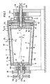
- Fig. 1 eine Vollmantelzentrifuge in rein schematischer Darstellung und im Schnitt entlang einer vertikalen, durch die Rotationsachse verlaufenden Ebene,
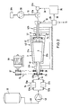
- Fig. 2 einen Funktionsstammbaum einer Schlammeindickanlage mit der Vollmantelzentrifuge nach Fig. 1.
- 1 is a full jacket centrifuge in a purely schematic representation and in section along a vertical plane extending through the axis of rotation,
- 2 shows a functional family tree of a sludge thickening system with the solid bowl centrifuge according to FIG. 1.
Fig. 1 zeigt die Vollmantelzentrifuge (40) mit einer auf Hohlwellen (41a, 41b) beidseitig in den Lagerböcken (42a, 42b) gelagerten Trommel (2). Im Innern der Trommel (2) befindet sich, in den Klärteich (3) eintauchend, ein hohler Verdrängungskörper (6). Dieser ist ebenfalls beidseitig auf den Hohlwellen (43a) bzw. (43b) in den Lagerböcken (42a) und (42b) drehbar gelagert. Durch die Hohlwelle (43a) wird der Zentrifuge (40) Suspension, angedeutet durch den Pfeil (44), zugeführt. Die Suspension (44) tritt durch die Öffnungen (45) in der Hohlwelle (43) aus und gelangt in das Innere der Trommel (2) und bildet dort im Betrieb den Klärteich (3) aus.1 shows the solid bowl centrifuge (40) with a drum (2) mounted on hollow shafts (41a, 41b) on both sides in the bearing blocks (42a, 42b). Inside the drum (2) there is a hollow displacement body (6) immersed in the clarification pond (3). This is also rotatably supported on both sides on the hollow shafts (43a) and (43b) in the bearing blocks (42a) and (42b). The centrifuge (40) suspension, indicated by the arrow (44), is fed through the hollow shaft (43a). The suspension (44) exits through the openings (45) in the hollow shaft (43) and enters the interior of the drum (2) and forms the clarification pond (3) there during operation.
Die Hohlwelle (41a) der Trommel (2) weist zum Antrieb eine Keilriemenscheibe (26) und die Hohlwelle (43a) des Verdrängungskörpers eine Keilriemenscheibe (25) auf. Diese bilden gemäß Fig. 2 im Zusammenwirken mit dem Keilriemenpulli (27) des Antriebsmotors (28) einen Differential-Keilriementrieb (24) für die Zentrifuge (40).The hollow shaft (41a) of the drum (2) has a V-belt pulley (26) for driving and the hollow shaft (43a) of the displacement body has a V-belt pulley (25). 2, in cooperation with the V-belt sweater (27) of the drive motor (28), form a differential V-belt drive (24) for the centrifuge (40).
Der Mantel (1) der Trommel (2) ist in Durchflußrichtung des Klärteiches (3) vorzugsweise mit einer konischen Erweiterung (4) ausgebildet. Hierdurch wird der gemäß Fig. 1 auf der linken Seite durch die Öffnungen (45) eintretenden Suspension im künstlichen Schwerefeld eine Beschleunigungskomponente für die Inhaltsteilchen der schwereren Phase in Durchflußrichtung (10) erteilt. Die Teilchen haben ersichtlicherweise das Bestreben, im Klärteich (3) zum Bereich des größten Trommeldurchmessers nach rechts zu wandern und dabei zu sedimentieren. Die Zentrifuge (40) arbeitet im Gleichstrom unter Einhaltung optimaler Trennschärfebedingungen, wobei der Verdrängungskörper (6), als glatter Kegelstumpf ausgebildet, an keiner Stelle des Klärteiches (3) störende Wirbel oder ein Gegenströmungsfeld verursacht.The jacket (1) of the drum (2) is preferably formed with a conical extension (4) in the flow direction of the clarifying pond (3). As a result, the suspension entering the artificial gravity field through the openings (45) on the left-hand side according to FIG. 1 becomes an acceleration component for the content particles of the heavier phase in the flow direction (10) granted. The particles obviously have the tendency to migrate to the right in the clarification pond (3) to the area of the largest drum diameter and thereby sediment. The centrifuge (40) works in direct current while maintaining optimal separation sharpness conditions, the displacement body (6), designed as a smooth truncated cone, not causing disturbing eddies or a counterflow field at any point in the clarifying pond (3).
Wie Fig. 1 weiter zeigt, ist das Austragsorgan (8) für die leichte Phase (14) zu einem Überlauf (8a) an der Trommelstirnwand (16) geführt und das Austragsorgan (9) für die schwerere Phase (13) vom tiefsten Bereich (17) des Klärteichs (3) ausgehend mit einer Fördereinrichtung (18) ausgebildet und in die Hohlwelle (43b) ausmündend angeordnet.As further shown in FIG. 1, the discharge element (8) for the light phase (14) leads to an overflow (8a) on the drum end wall (16) and the discharge element (9) for the heavier phase (13) from the deepest area ( 17) of the clarification pond (3), starting with a conveying device (18), and arranged to open into the hollow shaft (43b).
Diese Fördereinrichtung (18) ist als Druckluftflüssigkeitsheber (37a, 37b) ausgebildet und an eine durch die Hohlwelle (43b) in das Innere der Trommel (2) geführte Druckluftleitung (19) angeschlossen. Die Anordnung ist überraschend einfach, zugleich funktionell zuverlässig und energetisch ökonomisch.This conveying device (18) is designed as a compressed air liquid lifter (37a, 37b) and connected to a compressed air line (19) which is guided through the hollow shaft (43b) into the interior of the drum (2). The arrangement is surprisingly simple, at the same time functionally reliable and energetically economical.
Vorteilhaft ist die konische Erweiterung (4) des Mantels (1) der Trommel (2) mit einem Öffnungswinkel ( α 1) zwischen 1° und 8°, vorzugsweise zwischen 3° und 5° und der Ver drängungskörper (6) mit einem rotationssymmetrischen Mantel (20) in Form eines Kegelstumpfes mit einem Öffnungswinkel ( α 2) ausgebildet, der im wesentlichen dem Öffnungswinkel ( α 1) des Trommelmantels (1) entspricht.The conical widening (4) of the jacket (1) of the drum (2) with an opening angle (α 1) between 1 ° and 8 °, preferably between 3 ° and 5 ° and the ver is advantageous thrust body (6) with a rotationally symmetrical jacket (20) in the form of a truncated cone with an opening angle (α 2) which essentially corresponds to the opening angle (α 1) of the drum shell (1).
Hierdurch ergibt sich im Bereich des Verdrängungskörpers (6) ein Klärteich (3) mit vergleichsweise großer Oberfläche, woraus Sedimentationsbedingungen mit optimalen Parametern resultieren.This results in a clarification pond (3) with a comparatively large surface area in the area of the displacement body (6), which results in sedimentation conditions with optimal parameters.
Eine zweckmäßige Ausgestaltung der Zentrifuge sieht weiter vor, daß der Verdrängungskörper (6) Räumorgane (21) aufweist.An expedient embodiment of the centrifuge further provides that the displacement body (6) has clearing elements (21).
Es ist bekannt, daß es bei einer Vollmantelzentrifuge an der Innenwandung (5) des Mantels (1) zu Feststoffablagerungen kommen kann, die das Fließvermögen der schwereren Phase (13) in Richtung (10) zum tiefsten Bereich (17) des Klärteiches (3) erschweren oder verhindern. Derartige Ansatzbildungen entstehen vorzugsweise bei der Entwässerung von zähflüssigen, pastösen Schlämmen, insbesondere Klärwerksschlämmen.It is known that a solid bowl centrifuge on the inner wall (5) of the jacket (1) can lead to solid build-up, which causes the flow of the heavier phase (13) in the direction (10) to the deepest area (17) of the clarification pond (3) complicate or prevent. Such batches are preferably formed during the dewatering of viscous, pasty sludge, in particular sewage treatment plant sludge.
Die Räumorgane (21) sind bei der beispielhaft gezeigten Ausführung zwei gegenüberliegend auf dem Mantel (20) senkrecht stehende Räumleisten. Durch diese werden die bei der Trennung des Feststoff-Flüssigkeitsgemisches anfallenden Feststoffe im Bereich der inneren Trommelwandung (5) in Bewegung gehalten, so daß sie sich nicht festsetzen können.The clearing elements (21) are two clearing strips standing vertically opposite one another on the jacket (20) in the embodiment shown as an example. Through this the accumulation of the solid-liquid mixture Solids in the area of the inner drum wall (5) kept in motion so that they cannot get stuck.
Dabei kann jedes Räumorgan (21a, 21b) als Wendel mit sehr großer Steigung mit einem Steigungswinkel (β) gegenüber der Rotationsachse (x-x) des Systems zwischen 0 und 10°, vorzugsweise zwischen 3 und 5° ausgebildet sein. Durch diese Maßnahme wird der Transport der Feststoffe in der Zentrifugentrommel (2) zum Feststoffaustragsende (15) hin unterstützt und vergleichmäßigt.Each broach (21a, 21b) can be designed as a helix with a very large pitch with a pitch angle (β) with respect to the axis of rotation (x-x) of the system between 0 and 10 °, preferably between 3 and 5 °. This measure supports and evenens the transport of the solids in the centrifuge drum (2) to the solids discharge end (15).
Mit Vorteil erfordert die geringe Rotationsgeschwindigkeitsdifferenz zwischen dem Veredrängungskörper (6) mit Räumorganen (21a, 21b) gegenüber der Trommel (2) im Gegensatz zum Feststofftransport durch eine Schnickenwendel nur einen vernachlässigbar kleinen Teil an Antriebsenergie.Advantageously, the small difference in rotational speed between the displacement body (6) with clearing elements (21a, 21b) compared to the drum (2), in contrast to the transport of solids by means of a helix, requires only a negligibly small amount of drive energy.
Deshalb kann dieser Antrieb sehr einfach, vorzugsweise als Keilriementrieb ausgebildet sein.Therefore, this drive can be designed very simply, preferably as a V-belt drive.
Im System dieses Keilriementriebes (24) weist die Hohlwelle (43a) des Verdrängungskörpers (6) eine erste Keilriemenscheibe (25) und die hohle Antriebswelle (41a) der Trommel (2) eine zweite Keilriemenscheibe (26) auf. Diese ergeben in Zusammenwirken mit dem Keilriemenpulli (27) des gemeinsamen Antriebsmotors (28) bei entsprechender Bemessung eine vorgesehene RotationsDifferenzgeschwindigkeit zwischen Trommel (2) und Verdrängungskörper (6) - Fig. 2.In the system of this V-belt drive (24), the hollow shaft (43a) of the displacement body (6) has a first V-belt pulley (25) and the hollow drive shaft (41a) of the drum (2) has a second V-belt pulley (26). This results in cooperation with the V-belt sweater (27) common drive motor (28) with appropriate dimensioning an intended rotational differential speed between drum (2) and displacement body (6) - Fig. 2.
Eine weitere Verminderung der erforderlichen Antriebsleistung für das System der Zentrifuge (40) kann auch noch dadurch erreicht werden, daß im Innern der Trommel (2) Strömungsleitorgane (51, 52) beispielsweise in Form von gekrümmten Schaufeln nach Art eines Radialpumpen bzw. -turbinenlaufrades angeordnet sind, durch welche kinetische Energie in potentielle Energie umgewandelt wird, und umgekehrt. Diese an sich bekannte Anordnung verbessert den wirtschaftlichen Betrieb der Zentrifuge.A further reduction in the drive power required for the system of the centrifuge (40) can also be achieved by arranging flow guide elements (51, 52) in the interior of the drum (2), for example in the form of curved blades in the manner of a radial pump or turbine impeller are through which kinetic energy is converted into potential energy, and vice versa. This known arrangement improves the economic operation of the centrifuge.
Wie aus dem Verfahrensschaubild einer Eindikkungsanlage nach Fig. 2 mit einer Vollmantelzentrifuge (40) zu ersehen ist, kann dem Austrag (31) der schwereren Phase (13) eine Meßeinrichtung (29) zur Ermittlung des Feststoffgehaltes zugeordnet und über eine Signalleitung (30) sowie eine Rechnereinheit (35) und eine Steuerleitung (36) einem Mengenregelorgan (32a, 32b) in der Druckluftleitung (19) des Druckluftflüssigkeitshebers (37) zugeordnet sein, welche über die Steuerleitung (36) dem Stellorgan (32a) des Druckluftmengenreglers (32b) aufgeschaltet ist. Die Drucklufterzeugungsanlage besitst eine Druckluftpumpe (38) mit Motor (38a). Über die Regeleinrichtung (29, 35, 32) wird die Austragsmenge der feststoffreichen Phase (13) nach Maßgabe einer vorgegebenen Fördercharakteristik des Druckluftflüssigkeitshebers (37) so beeinflußt, daß deren Feststoffgehalt konstant bleibt.As can be seen from the process diagram of a thickening plant according to FIG. 2 with a solid jacket centrifuge (40), the discharge (31) of the heavier phase (13) can be assigned a measuring device (29) for determining the solids content and via a signal line (30) and a computer unit (35) and a control line (36) can be assigned to a quantity control element (32a, 32b) in the compressed air line (19) of the compressed air liquid lifter (37), which is connected to the control element (32a) of the compressed air quantity regulator (32b) via the control line (36) is. The compressed air generation system has a compressed air pump (38) with a motor (38a). Via the control device (29, 35, 32) the discharge amount of the solid phase (13) is influenced in accordance with a predetermined delivery characteristic of the compressed air liquid lifter (37) so that its solids content remains constant.
Auf der Seite der zuzuführenden Suspension (44) ist dem Eintragsorgan (43a, 45) ein Grobstoffabscheider (34) vorgeschaltet.On the side of the suspension (44) to be supplied, a coarse material separator (34) is connected upstream of the entry element (43a, 45).
Dieser weist zweckmäßig zwei Einheiten (33a, 33b) in Tandemanordnung auf. Die Suspension (44) wird beispielsweise aus einem Vorratsbehälter (39) mit der Leitung (48) durch die Förderpumpe (49) und eine umschaltbare Ventilbatterie (50a, 50b) abwechselnd durch Filter (33a) oder Filter (33b) in die Zentrifuge (40) eingespeist. Dabei ermöglicht die Tandemanordnung einen wechselseitigen Betrieb, wobei jeweils das nicht in Betrieb befindliche Filter ohne Betriebsunterbrechung gereinigt und dann wieder in den Zulauf eingeschaltet werden kann.This expediently has two units (33a, 33b) in tandem arrangement. The suspension (44) is, for example, from a storage container (39) with the line (48) through the feed pump (49) and a switchable valve bank (50a, 50b) alternately through filter (33a) or filter (33b) into the centrifuge (40 ) fed. The tandem arrangement enables two-way operation, whereby the filter that is not in operation can be cleaned without interrupting operation and then switched on again in the inlet.
Claims (9)
Applications Claiming Priority (2)
| Application Number | Priority Date | Filing Date | Title |
|---|---|---|---|
| DE3744093 | 1987-12-24 | ||
| DE19873744093 DE3744093A1 (en) | 1987-12-24 | 1987-12-24 | FULL-COAT CENTRIFUGE |
Publications (2)
| Publication Number | Publication Date |
|---|---|
| EP0322516A2 true EP0322516A2 (en) | 1989-07-05 |
| EP0322516A3 EP0322516A3 (en) | 1990-04-25 |
Family
ID=6343599
Family Applications (1)
| Application Number | Title | Priority Date | Filing Date |
|---|---|---|---|
| EP88115690A Withdrawn EP0322516A3 (en) | 1987-12-24 | 1988-09-23 | Solid bowl centrifuge |
Country Status (4)
| Country | Link |
|---|---|
| US (1) | US4898571A (en) |
| EP (1) | EP0322516A3 (en) |
| JP (1) | JPH01203063A (en) |
| DE (1) | DE3744093A1 (en) |
Cited By (1)
| Publication number | Priority date | Publication date | Assignee | Title |
|---|---|---|---|---|
| CN110388465A (en) * | 2019-07-26 | 2019-10-29 | 浙江轻机实业有限公司 | A kind of two-stage material-pushing centrifuge reverse osmosis leakage encapsulating method |
Families Citing this family (21)
| Publication number | Priority date | Publication date | Assignee | Title |
|---|---|---|---|---|
| DE4104483A1 (en) * | 1991-02-14 | 1992-08-20 | Kloeckner Humboldt Deutz Ag | METHOD FOR OPERATING A SNAIL CENTRIFUGE AND CENTRIFUGE THEREFOR |
| JPH07508453A (en) * | 1992-04-10 | 1995-09-21 | ワーマン・インターナショナル・リミテッド | Equipment for separating materials |
| DE4231063A1 (en) * | 1992-09-17 | 1994-03-24 | Westfalia Separator Ag | Horizontal decanter centrifuge with partial hydraulic support and reduced re-suspension of solids - by local increased clearance of bowl and screw |
| US7211037B2 (en) * | 2002-03-04 | 2007-05-01 | Therakos, Inc. | Apparatus for the continuous separation of biological fluids into components and method of using same |
| US7479123B2 (en) | 2002-03-04 | 2009-01-20 | Therakos, Inc. | Method for collecting a desired blood component and performing a photopheresis treatment |
| DE10223802B4 (en) * | 2002-05-29 | 2005-06-09 | Westfalia Separator Ag | Solid bowl centrifuge |
| DE10336350B4 (en) * | 2003-08-08 | 2007-10-31 | Westfalia Separator Ag | Solid bowl centrifuge, with paring disc |
| US20050049539A1 (en) * | 2003-09-03 | 2005-03-03 | O'hara Gerald P. | Control system for driving fluids through an extracorporeal blood circuit |
| US7476209B2 (en) | 2004-12-21 | 2009-01-13 | Therakos, Inc. | Method and apparatus for collecting a blood component and performing a photopheresis treatment |
| US7603839B2 (en) * | 2005-12-22 | 2009-10-20 | Pratt & Whitney Canada Corp. | Scavenge pump system and method |
| GB0621614D0 (en) * | 2006-10-31 | 2006-12-06 | Mozley Ltd | Improvements in and relating to solids sparators |
| CA2684691C (en) * | 2008-01-31 | 2010-09-07 | Daniel Guy Pomerleau | System and method for improving the separation of entrained solids from a solution within a centrifuge |
| DK2582440T3 (en) * | 2010-06-15 | 2019-07-22 | Centrisys Corp | CENTRIFUGAL LIQUID SEPARATION MACHINE USING PRESSURE AIR TO PROMOTE SOLID SUPPLY |
| CN103443577B (en) * | 2010-07-01 | 2016-05-25 | 森特瑞斯公司 | Make multiphase solid mobile centrifugal liquid seperator efficiently in heavy phase discharge stream |
| WO2013000072A1 (en) * | 2011-06-29 | 2013-01-03 | The University Of British Columbia | Method and apparatus for continuously fractionating particles contained within a viscoplastic fluid |
| GB201321250D0 (en) | 2013-12-02 | 2014-01-15 | Gm Innovations Ltd | An apparatus for removing impurities from a fluid stream |
| GB201703110D0 (en) | 2017-02-27 | 2017-04-12 | Gm Innovations Ltd | An apparatus for seperating components of a fluid stream |
| GB2572331B (en) | 2018-03-26 | 2022-03-09 | Gm Innovations Ltd | An apparatus for separating components of a fluid stream |
| GB2606484A (en) | 2018-04-24 | 2022-11-09 | Gm Innovations Ltd | An apparatus for producing potable water |
| CN109046794A (en) * | 2018-08-13 | 2018-12-21 | 贵州开磷机电装备工程有限责任公司 | A kind of special seal device inside horizontal screw machine |
| CN109320041B (en) * | 2018-10-22 | 2023-04-18 | 长沙理工大学 | Slurry treatment system |
Citations (4)
| Publication number | Priority date | Publication date | Assignee | Title |
|---|---|---|---|---|
| DE3317047A1 (en) * | 1982-05-28 | 1984-01-05 | VEB Chemieanlagenbaukombinat Leipzig-Grimma, DDR 7240 Grimma | Solid bowl screw centrifuge |
| DE3335873A1 (en) * | 1983-07-25 | 1985-02-21 | Klöckner-Humboldt-Deutz AG, 5000 Köln | Solid bowl screw centrifuge for the separation of a solid-liquid mixture |
| US4566873A (en) * | 1984-03-28 | 1986-01-28 | Kotobuki Engineering & Manufacturing Co., Ltd. | Screw decanter type centrifugal concentrating machine |
| EP0237067A2 (en) * | 1986-03-14 | 1987-09-16 | Krauss-Maffei Aktiengesellschaft | Solid bowl centrifuge |
Family Cites Families (2)
| Publication number | Priority date | Publication date | Assignee | Title |
|---|---|---|---|---|
| US3795361A (en) * | 1972-09-06 | 1974-03-05 | Pennwalt Corp | Centrifuge apparatus |
| US4790806A (en) * | 1987-04-21 | 1988-12-13 | High Robert E | Decanter centrifuge incorporating airlift device |
-
1987
- 1987-12-24 DE DE19873744093 patent/DE3744093A1/en not_active Withdrawn
-
1988
- 1988-09-23 EP EP88115690A patent/EP0322516A3/en not_active Withdrawn
- 1988-11-30 US US07/277,978 patent/US4898571A/en not_active Expired - Fee Related
- 1988-12-23 JP JP63323809A patent/JPH01203063A/en active Pending
Patent Citations (4)
| Publication number | Priority date | Publication date | Assignee | Title |
|---|---|---|---|---|
| DE3317047A1 (en) * | 1982-05-28 | 1984-01-05 | VEB Chemieanlagenbaukombinat Leipzig-Grimma, DDR 7240 Grimma | Solid bowl screw centrifuge |
| DE3335873A1 (en) * | 1983-07-25 | 1985-02-21 | Klöckner-Humboldt-Deutz AG, 5000 Köln | Solid bowl screw centrifuge for the separation of a solid-liquid mixture |
| US4566873A (en) * | 1984-03-28 | 1986-01-28 | Kotobuki Engineering & Manufacturing Co., Ltd. | Screw decanter type centrifugal concentrating machine |
| EP0237067A2 (en) * | 1986-03-14 | 1987-09-16 | Krauss-Maffei Aktiengesellschaft | Solid bowl centrifuge |
Cited By (1)
| Publication number | Priority date | Publication date | Assignee | Title |
|---|---|---|---|---|
| CN110388465A (en) * | 2019-07-26 | 2019-10-29 | 浙江轻机实业有限公司 | A kind of two-stage material-pushing centrifuge reverse osmosis leakage encapsulating method |
Also Published As
| Publication number | Publication date |
|---|---|
| DE3744093A1 (en) | 1989-07-13 |
| US4898571A (en) | 1990-02-06 |
| EP0322516A3 (en) | 1990-04-25 |
| JPH01203063A (en) | 1989-08-15 |
Similar Documents
| Publication | Publication Date | Title |
|---|---|---|
| EP0322516A2 (en) | Solid bowl centrifuge | |
| DE3202294C1 (en) | Continuously working full-jacket countercurrent centrifugal extractor | |
| DE3318793A1 (en) | DEVICE FOR DEHUMIDIFYING SLUDGE | |
| DE1532683A1 (en) | Sieve centrifuge | |
| DE3224204A1 (en) | CENTRIFUGE | |
| DE2130633A1 (en) | FULL-CASED SCREW CENTRIFUGE | |
| WO2003078070A1 (en) | Helical conveyor centrifuge | |
| DE1801426A1 (en) | Centrifugal concentrator or centrifugal separator | |
| DE3904151A1 (en) | Centrifuge | |
| DE3328303C1 (en) | Device for dewatering and drying plastic granules | |
| DE966139C (en) | Centrifuge with a rotating housing and a rotating conveyor | |
| DE102018113135A1 (en) | Device for sewage sludge dewatering | |
| DE60124554T2 (en) | SEPARATOR | |
| DE1632324A1 (en) | Funnel centrifuge | |
| EP0163112B1 (en) | Method and device for the centrifugal separation of fine-grained mineral mixtures | |
| EP0012461B1 (en) | Coal gasification plant | |
| DE1532711B1 (en) | Continuously working solid bowl centrifuge | |
| EP0998341A1 (en) | Method and device for separating materials and guiding device therefor | |
| CH433192A (en) | Device for separating and fractionating material dissolved or suspended in a liquid | |
| DE2152839A1 (en) | DC FULL-SLEEVE CENTRIFUGE WITH ACCELERATOR | |
| DE723408C (en) | Full jacket extractor for separating liquids from pulpy or mainly liquid material | |
| DE963409C (en) | Screw centrifuge for muddy or fine-grained liquid-solid mixtures | |
| DE102020114665B4 (en) | flow centrifuge | |
| DE4041923A1 (en) | Auger-type slurry centrifuge - has auger turns of finer pitch inside tapering portion of cylindrical drum | |
| DE2229809C3 (en) | DC solid bowl screw centrifuge |
Legal Events
| Date | Code | Title | Description |
|---|---|---|---|
| PUAI | Public reference made under article 153(3) epc to a published international application that has entered the european phase |
Free format text: ORIGINAL CODE: 0009012 |
|
| AK | Designated contracting states |
Kind code of ref document: A2 Designated state(s): DE FR GB IT NL SE |
|
| PUAL | Search report despatched |
Free format text: ORIGINAL CODE: 0009013 |
|
| AK | Designated contracting states |
Kind code of ref document: A3 Designated state(s): DE FR GB IT NL SE |
|
| STAA | Information on the status of an ep patent application or granted ep patent |
Free format text: STATUS: THE APPLICATION IS DEEMED TO BE WITHDRAWN |
|
| 18D | Application deemed to be withdrawn |
Effective date: 19901026 |