EP0321994B1 - Aircraft exit door locking system - Google Patents
Aircraft exit door locking system Download PDFInfo
- Publication number
- EP0321994B1 EP0321994B1 EP19880201367 EP88201367A EP0321994B1 EP 0321994 B1 EP0321994 B1 EP 0321994B1 EP 19880201367 EP19880201367 EP 19880201367 EP 88201367 A EP88201367 A EP 88201367A EP 0321994 B1 EP0321994 B1 EP 0321994B1
- Authority
- EP
- European Patent Office
- Prior art keywords
- lock
- logic circuit
- aircraft
- exit door
- unlock
- Prior art date
- Legal status (The legal status is an assumption and is not a legal conclusion. Google has not performed a legal analysis and makes no representation as to the accuracy of the status listed.)
- Expired - Lifetime
Links
Images


Classifications
-
- B—PERFORMING OPERATIONS; TRANSPORTING
- B64—AIRCRAFT; AVIATION; COSMONAUTICS
- B64C—AEROPLANES; HELICOPTERS
- B64C1/00—Fuselages; Constructional features common to fuselages, wings, stabilising surfaces or the like
- B64C1/14—Windows; Doors; Hatch covers or access panels; Surrounding frame structures; Canopies; Windscreens accessories therefor, e.g. pressure sensors, water deflectors, hinges, seals, handles, latches, windscreen wipers
- B64C1/1407—Doors; surrounding frames
-
- E—FIXED CONSTRUCTIONS
- E05—LOCKS; KEYS; WINDOW OR DOOR FITTINGS; SAFES
- E05B—LOCKS; ACCESSORIES THEREFOR; HANDCUFFS
- E05B47/00—Operating or controlling locks or other fastening devices by electric or magnetic means
- E05B47/0001—Operating or controlling locks or other fastening devices by electric or magnetic means with electric actuators; Constructional features thereof
- E05B47/0002—Operating or controlling locks or other fastening devices by electric or magnetic means with electric actuators; Constructional features thereof with electromagnets
-
- E—FIXED CONSTRUCTIONS
- E05—LOCKS; KEYS; WINDOW OR DOOR FITTINGS; SAFES
- E05B—LOCKS; ACCESSORIES THEREFOR; HANDCUFFS
- E05B47/00—Operating or controlling locks or other fastening devices by electric or magnetic means
- E05B47/06—Controlling mechanically-operated bolts by electro-magnetically-operated detents
- E05B47/0607—Controlling mechanically-operated bolts by electro-magnetically-operated detents the detent moving pivotally or rotatively
-
- E—FIXED CONSTRUCTIONS
- E05—LOCKS; KEYS; WINDOW OR DOOR FITTINGS; SAFES
- E05B—LOCKS; ACCESSORIES THEREFOR; HANDCUFFS
- E05B47/00—Operating or controlling locks or other fastening devices by electric or magnetic means
- E05B47/0001—Operating or controlling locks or other fastening devices by electric or magnetic means with electric actuators; Constructional features thereof
- E05B47/0002—Operating or controlling locks or other fastening devices by electric or magnetic means with electric actuators; Constructional features thereof with electromagnets
- E05B47/0006—Operating or controlling locks or other fastening devices by electric or magnetic means with electric actuators; Constructional features thereof with electromagnets having a non-movable core; with permanent magnet
Definitions
- This invention relates to aircraft exit door locking systems and, more particularly, to automatic locking systems which prevent inadvertent operation of aircraft exit opening means during flight.
- U.S. Patent No. 3,829,834 is representative of the patent literature prior art and shows a predetermined combination of manually operated switches to actuate a motor for unlocking purposes.
- an aircraft exit door flight lock system comprising in combination: a voting logic circuit; inertial reference system logic circuit means; pitot system logic circuit means; air/ground system logic circuit means for indicating whether the aircraft is on the ground or airborne; said voting logic circuit being responsive to said inertial reference system logic circuit means, said pitot system logic circuit means and said air/ ground system logic circuit means for providing a signal representative of a lock/unlock decision.
- the present invention also provides an aircraft cabin exit door lock control system comprising in combination: an exit door locking mechanism having a lock and a motor for closing said lock; means for removing power from said closing motor after the exit door is locked; and, electromagnetic means for holding said lock in position upon removal of power from said closing motor after said exit door is locked, and for releasing said lock upon removal of power from said electro magnetic means.
- An added feature of the triple voting logic is that the total flight lock system is not sensitive to timing of the decisions. Since the point at which the inertial reference system, pitot system and air/ground system make their respective decisions to energize or deenergize are a function of external constraints (e.g. atmospheric pressure, altitude, pilot decision to lift off the runway, etc%) the chance that they will all agree simultaneously is very remote. The majority decision will rule. Therefore, on landing, for example, the flight lock system will remain locked until at least two decisions change states. The remaining decision is overruled if in disagreement.
- external constraints e.g. atmospheric pressure, altitude, pilot decision to lift off the runway, etc.
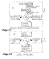
- the first input logic system is the inertial reference system 10 shown in detail in FIG. 2A.
- horizontal aircraft acceleration is sensed by an accelerometer.
- the accelerometer output is then input into an integrator which continuously outputs the current horizontal aircraft velocity.
- This velocity is then compared to a reference velocity at which the aircraft exit flight lock system should either change state from deenergized to energized or vice versa.
- the reference velocity at which state change occurs can either be aircraft rotation speed or some other convenient velocity sufficiently high to prevent spurious signals, due to wind gusts, from energizing the aircraft exit flight lock system.
- the resulting decision 14 to energize or deenergize from the inertial reference system logic 10 is then input into the voting logic section 7 of the aircraft exit flight lock system where it and the remaining two system logic decisions are voted on.
- the second input logic system is the pitot system 20.
- Aircraft horizontal velocity is sensed by a pitot static probe unit which outputs an electrical signal corresponding to the measured delta pressure.
- This pressure is then compared to a reference pressure corresponding to the velocity at which the aircraft exit flight lock system should change state.
- the reference pressure should be high enough to prevent spurious signals.
- the resulting signal to energize or deenergize from the pitot system logic 15 is then input into voting logic section 7 of the aircraft exit flight lock system where it is voted on along with the inertial reference system logic decision 14 and the logic decision 16 from the third system 13.
- the third system 13 comprises an air/ground system known in the prior art.
- this system either the rotation of the main landing gear truck or extension of the main landing gear oleo, both of which are motion inputs, activates a switch or switches. The activation of these switches determine if the landing gear have left or contacted the ground based on the previous states they were in. If the landing gear have left the ground surface a command to energize 16 is input to the voting logic section 7 where it is voted on along with the two previously mentioned logic outputs 14 and 15. Similarly, if the landing gear have contacted the ground a command to deenergize is input to voting logic section 7.
- a final decision 8 to lock or unlock i.e. energize or deenergize
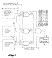
- the voting section ensures that the majority decision is acted upon as shown in the truth table of FIG. 1. This voting eliminates the susceptability to wheel up landings. It also eliminates the timing of decision inputs into the voting section which are a function of variable external parameters such as altitude and human reaction for example. Additionally, the single failure of the air/ground system or one of the other input logic systems, does not result in the unlocking of the aircraft exit in flight. With the present invention dual failures must occur before unlocking results.
- the final decision 8 from voting logic 7 of FIG. 1 to lock or unlock the aircraft exit flight lock system controls the state of lock/unlock logic switch 9.
- power from a 28 VDC source 12 energizes the coil of a relay 110 which transfers power to both the electromagnet 114 of lock actuator assembly 113 and permanent magnet DC motor 115 through the delay before break relay 116 which controls the duration of power to permanent magnet DC motor 115 of lock actuator assembly 113.
- delay before break relay 116 makes contact energizing coil 111 inside the relay which removes power to permanent magnet DC motor 115.
- the mechanical hardware of the aircraft flight lock system is housed in the aircraft exit structure 130.
- the lock actuator assembly 113 consisting of the electromagnet 114, permanent magnet DC motor 115, return spring 128, output shaft rod end 129 and other components internal to actuator assembly 113, is attached to the aircraft exit structure 130 and locking lever assembly 118.
- Locking lever assembly 118 consisting of magnetic target 112, swivel 117 and pawl 122, is attached to output shaft rod end 129 and to aircraft exit structure 130.
- pawl 122 of locking lever assembly 118 is rotated about pivot 121 into a position of noninterference or interference with appendage 127 on the aircraft exit interior handle shaft 125.
- Pivot 121 for the locking lever assembly is between the sheet metal bracket 119 and handle box assembly 124; both of which are attached to aircraft exit structure 130.
- a spring 120 between locking lever 118 and aircraft exit structure 130 along with spring 128 on lock actuator assembly 113 and the weight of locking lever assembly 118 provides a fail operational system since each item by itself is capable of causing unlocking to occur by backdriving permanent magnet DC motor 115 and gearing internal to lock actuator assembly 113 against frictional losses and residual magnetism of the magnetic target 112 when power is removed.
- Electromagnets work over a very short stroke range. Therefore, to overcome the weight of locking lever assembly 118 and the dual springs 120 and 128 while providing the required stroke, permanent magnet DC motor 115 is required to retract the output shaft rod end 129 via gearing and an internal ball screw arrangement internal to the locking actuator assembly 113.
- the purpose of the swivel 117 is to ensure that magnetic target 112 always comes into contact with the face of electromagnet 114.
Description
- This invention relates to aircraft exit door locking systems and, more particularly, to automatic locking systems which prevent inadvertent operation of aircraft exit opening means during flight.
- Currently, Part 25 of the Federal Aviation Administration (F.A.A.) Regulations requires that aircraft exits be protected against inadvertent opening in flight by persons. The F.A.A. Regulations also require that operation of a single handle be used to open an aircraft exit. The requirement for a single handle prevents the use of manually operated locks to prevent handle operation.
- To meet these requirements, aircraft exits have previously been designed such that pressurization loads in flight prevent operation of the handle. However, the point where pressurization loads exceed the mechanical advantage at the handle, occurs after the aircraft has become airborne and pressurized to the appropriate level. The altitude at which the exit becomes locked is variable due to pressurization schedule, atmospheric conditions and exit linkage design.
- Further prior designs have incorporated a flight lock system which was activated by air/ground logic controlled by the landing gear truck tilt. As the aircraft main body and wing landing gear departed the ground the rotation of the gear trucks would activate switches which in turn would energize an electromechanical actuator thereby rotating a pawl into a position of interference with the exit handle thus preventing rotation while in flight.
- U.S. Patent No. 3,829,834 is representative of the patent literature prior art and shows a predetermined combination of manually operated switches to actuate a motor for unlocking purposes.
- It is accordingly an object of the present invention to provide an automatically engaged and disengaged exit door flight lock system.
- According to the present invention there is provided an aircraft exit door flight lock system comprising in combination: a voting logic circuit; inertial reference system logic circuit means; pitot system logic circuit means; air/ground system logic circuit means for indicating whether the aircraft is on the ground or airborne; said voting logic circuit being responsive to said inertial reference system logic circuit means, said pitot system logic circuit means and said air/ ground system logic circuit means for providing a signal representative of a lock/unlock decision. As long as at least two or more decisions agree the majority decision is released to the locking assembly. Should one decision disagree (e.g. the air/ground system decision is to energize the locking assembly during a gear up landing and the other two systems say deenergize) the one in disagreement is overruled. This provides a automatic fail operational system which does not require pilot intervention to deenergize the locking assembly on the ground. Similarly, if one system should fail in flight (e.g. the pilot system) the remaining two systems will ensure the exit remains locked.
- Furthermore, the present invention also provides an aircraft cabin exit door lock control system comprising in combination: an exit door locking mechanism having a lock and a motor for closing said lock; means for removing power from said closing motor after the exit door is locked; and, electromagnetic means for holding said lock in position upon removal of power from said closing motor after said exit door is locked, and for releasing said lock upon removal of power from said electro magnetic means.
- An added feature of the triple voting logic is that the total flight lock system is not sensitive to timing of the decisions. Since the point at which the inertial reference system, pitot system and air/ground system make their respective decisions to energize or deenergize are a function of external constraints (e.g. atmospheric pressure, altitude, pilot decision to lift off the runway, etc...) the chance that they will all agree simultaneously is very remote. The majority decision will rule. Therefore, on landing, for example, the flight lock system will remain locked until at least two decisions change states. The remaining decision is overruled if in disagreement.
-
- FIG. 1 is a diagram illustrating the inputs and decision logic section for a fail operational triple voting aircraft exit flight lock system utilizing triple dissimilar inputs;
- FIGS. 2A, 2B, and 2C represent the inertial reference system logic, pilot system logic and air/ground system logic shown in block diagram form in FIG. 1;
- FIG. 3 is an electrical schematic of the aircraft flight lock system responsive to the logic decision shown in the embodiment of FIG. 1; and
- FIG. 4 is an illustration of the aircraft exit flight lock system hardware responsive to the logic and electrical inputs shown in the embodiments of FIG. 1 and FIG. 3 respectively.
- As illustrated in the embodiment of FIGS. 1, 2A, 2B, and 2C, three dissimilar inputs are sensed and interpreted by three dissimilar systems. The first input logic system is the
inertial reference system 10 shown in detail in FIG. 2A. In this system horizontal aircraft acceleration is sensed by an accelerometer. The accelerometer output is then input into an integrator which continuously outputs the current horizontal aircraft velocity. This velocity is then compared to a reference velocity at which the aircraft exit flight lock system should either change state from deenergized to energized or vice versa. The reference velocity at which state change occurs can either be aircraft rotation speed or some other convenient velocity sufficiently high to prevent spurious signals, due to wind gusts, from energizing the aircraft exit flight lock system. The resultingdecision 14 to energize or deenergize from the inertialreference system logic 10 is then input into the voting logic section 7 of the aircraft exit flight lock system where it and the remaining two system logic decisions are voted on. - The second input logic system is the
pitot system 20. Aircraft horizontal velocity is sensed by a pitot static probe unit which outputs an electrical signal corresponding to the measured delta pressure. This pressure is then compared to a reference pressure corresponding to the velocity at which the aircraft exit flight lock system should change state. As in the inertial reference system, the reference pressure should be high enough to prevent spurious signals. The resulting signal to energize or deenergize from thepitot system logic 15 is then input into voting logic section 7 of the aircraft exit flight lock system where it is voted on along with the inertial referencesystem logic decision 14 and thelogic decision 16 from thethird system 13. - The
third system 13 comprises an air/ground system known in the prior art. In this system, either the rotation of the main landing gear truck or extension of the main landing gear oleo, both of which are motion inputs, activates a switch or switches. The activation of these switches determine if the landing gear have left or contacted the ground based on the previous states they were in. If the landing gear have left the ground surface a command to energize 16 is input to the voting logic section 7 where it is voted on along with the two previously mentionedlogic outputs - By inputting the three
logic outputs final decision 8 to lock or unlock (i.e. energize or deenergize) the aircraft exit flight lock system is made. The voting section ensures that the majority decision is acted upon as shown in the truth table of FIG. 1. This voting eliminates the susceptability to wheel up landings. It also eliminates the timing of decision inputs into the voting section which are a function of variable external parameters such as altitude and human reaction for example. Additionally, the single failure of the air/ground system or one of the other input logic systems, does not result in the unlocking of the aircraft exit in flight. With the present invention dual failures must occur before unlocking results. - Turning to FIG. 3, the
final decision 8 from voting logic 7 of FIG. 1 to lock or unlock the aircraft exit flight lock system controls the state of lock/unlock logic switch 9. When in the "LOCK" position, power from a 28VDC source 12 energizes the coil of arelay 110 which transfers power to both theelectromagnet 114 oflock actuator assembly 113 and permanentmagnet DC motor 115 through the delay beforebreak relay 116 which controls the duration of power to permanentmagnet DC motor 115 oflock actuator assembly 113. A few seconds afterlock actuator assembly 113 has engaged, delay beforebreak relay 116 makes contact energizing coil 111 inside the relay which removes power to permanentmagnet DC motor 115. Subsequent change of state of lock/unlock logic switch 9 to "UNLOCK" or removal of aircraft power due to loss of the aircraft engines or the manual override of the aircraft exit flight lock system by pulling circuit breaker 11, deenergizes the electromagnet thereby unlocking the exit. - Now turning to the embodiment of FIG. 4, the mechanical hardware of the aircraft flight lock system is housed in the
aircraft exit structure 130. Thelock actuator assembly 113, consisting of theelectromagnet 114, permanentmagnet DC motor 115,return spring 128, output shaft rod end 129 and other components internal toactuator assembly 113, is attached to theaircraft exit structure 130 and lockinglever assembly 118. Lockinglever assembly 118, consisting ofmagnetic target 112,swivel 117 andpawl 122, is attached to output shaft rod end 129 and toaircraft exit structure 130. As output shaft rod end 129 oflock actuator assembly 113 is extended or retracted,pawl 122 of lockinglever assembly 118 is rotated about pivot 121 into a position of noninterference or interference with appendage 127 on the aircraft exitinterior handle shaft 125. Pivot 121 for the locking lever assembly is between the sheet metal bracket 119 and handlebox assembly 124; both of which are attached toaircraft exit structure 130. When pawl 122 is in a position of interference, the handle is prevented from rotation since it is trapped between thepawl 122 and the inside handle travel limit stops 123 onhandle bearing housing 126. Aspring 120 between lockinglever 118 andaircraft exit structure 130 along withspring 128 onlock actuator assembly 113 and the weight of lockinglever assembly 118 provides a fail operational system since each item by itself is capable of causing unlocking to occur by backdriving permanentmagnet DC motor 115 and gearing internal to lockactuator assembly 113 against frictional losses and residual magnetism of themagnetic target 112 when power is removed. - Because of the long stroke required to efficiently provide clearance for handle rotation, the dual electrical components of the lock actuator are required. Electromagnets work over a very short stroke range. Therefore, to overcome the weight of locking
lever assembly 118 and thedual springs magnet DC motor 115 is required to retract the output shaft rod end 129 via gearing and an internal ball screw arrangement internal to the lockingactuator assembly 113. The purpose of theswivel 117 is to ensure thatmagnetic target 112 always comes into contact with the face ofelectromagnet 114.
Claims (3)
- An aircraft cabin exit door lock control system comprising in combination:
an exit door locking mechanism (113) having a lock and a motor (115) for closing said lock;
means (116) for removing power from said closing motor (115) after the exit door is locked; and,
electromagnetic means (114) for holding said lock in position upon removal of power from said closing motor (115) after said exit door is locked, and for releasing said lock upon removal of power from said electro magnetic means (114). - An aircraft exit door flight lock system comprising in combination:
a voting logic circuit (7);
inertial reference system logic circuit means (10);
pitot system logic circuit means (20);
air/ground system logic circuit means (13) for indicating whether the aircraft is on the ground or airborne;
said voting logic circuit (7) being responsive to said inertial reference system logic circuit means (10), said pitot system logic circuit means (20) and said air/ ground system logic circuit means (13) for providing a signal (D) representative of a lock/unlock decision (8). - The system according to claim 2 further including:
lock/unlock logic switch means (9) responsive to said signal representative of lock/unlock decision (8);
a relay (110) including an energizing coil;
a lock actuator assembly (113) including an electromagnet (114); and
said lock/unlock logic switch means (9) energizing said energizing coil of said relay means (110) and further transferring power to said electromagnet (114) when said lock/unlock logic switch means (9) is in a lock position.
Applications Claiming Priority (2)
| Application Number | Priority Date | Filing Date | Title |
|---|---|---|---|
| US13521887A | 1987-12-21 | 1987-12-21 | |
| US135218 | 1987-12-21 |
Publications (3)
| Publication Number | Publication Date |
|---|---|
| EP0321994A2 EP0321994A2 (en) | 1989-06-28 |
| EP0321994A3 EP0321994A3 (en) | 1990-02-28 |
| EP0321994B1 true EP0321994B1 (en) | 1993-01-13 |
Family
ID=22467080
Family Applications (1)
| Application Number | Title | Priority Date | Filing Date |
|---|---|---|---|
| EP19880201367 Expired - Lifetime EP0321994B1 (en) | 1987-12-21 | 1988-06-30 | Aircraft exit door locking system |
Country Status (2)
| Country | Link |
|---|---|
| EP (1) | EP0321994B1 (en) |
| DE (1) | DE3877546T2 (en) |
Families Citing this family (14)
| Publication number | Priority date | Publication date | Assignee | Title |
|---|---|---|---|---|
| US4994972A (en) * | 1989-11-06 | 1991-02-19 | Trw Technar Inc. | Apparatus and method employing multiple crash evaluation algorithms for actuating a restraint system in a passenger vehicle |
| US5040118A (en) * | 1989-11-06 | 1991-08-13 | Trw Technar Inc. | Apparatus and method employing multiple crash evaluation algorithms and evaluation expertise for actuating a restraint system in a passenger vehicle |
| US5251851A (en) * | 1990-07-11 | 1993-10-12 | Deutsche Aerospace Airbus Gmbh | Door operating mechanism for opening and closing an aircraft door in response to a stored program |
| DE4022067C2 (en) * | 1990-07-11 | 1994-06-09 | Deutsche Aerospace Airbus | Kinematics for an aircraft door |
| FR2695675B1 (en) * | 1992-07-21 | 1995-12-01 | Arouete J | DEVICE BY LINEAR OR ROTARY ELECTRO-MAGNETISM FOR MOVING AND RETAINING AN ELECTRO-MECHANICAL LOCK. |
| DE4309058C1 (en) * | 1993-03-20 | 1994-12-08 | Deutsche Aerospace Airbus | Arrangement to prevent the automatic opening of an improperly closed and locked door or flap in the fuselage |
| DE4401899C2 (en) * | 1994-01-24 | 1995-11-16 | Daimler Benz Aerospace Airbus | Locking device |
| DE4413307C2 (en) * | 1994-04-16 | 1997-03-06 | Eurocopter Deutschland | Door system, in particular for a passenger plane |
| DE19948844B4 (en) * | 1999-10-08 | 2004-03-25 | Airbus Deutschland Gmbh | Kinematics for an aircraft door |
| DE10037621C2 (en) | 2000-08-02 | 2002-09-19 | Eurocopter Deutschland | Control for a passenger door of an aircraft |
| DE10056994C1 (en) | 2000-11-17 | 2002-02-21 | Eurocopter Deutschland | Aircraft passenger door opening and closing control method has all or individual function steps controlled by door control unit switched between mechanical or electromechanical control mode |
| DE10223902B4 (en) | 2002-05-29 | 2009-04-30 | Eurocopter Deutschland Gmbh | Locking device of an outer door of an aircraft for locking a door kinematics |
| CN109071029B (en) | 2016-04-05 | 2022-08-09 | 空中客车德国运营有限责任公司 | Convertible display device for displaying emergency slide activation status in an aircraft |
| FR3105169B1 (en) * | 2019-12-19 | 2021-12-10 | Latecoere | Safety locking latch aircraft door comprising an electroactive polymer link |
Family Cites Families (2)
| Publication number | Priority date | Publication date | Assignee | Title |
|---|---|---|---|---|
| US4681286A (en) * | 1982-09-30 | 1987-07-21 | The Boeing Company | Door anti-hijacking latch/lock mechanism with pneumatic decompression override |
| US4522359A (en) * | 1982-09-30 | 1985-06-11 | The Boeing Company | Door anti-hijacking latch/lock mechanism with pneumatic decompression override |
-
1988
- 1988-06-30 DE DE19883877546 patent/DE3877546T2/en not_active Expired - Lifetime
- 1988-06-30 EP EP19880201367 patent/EP0321994B1/en not_active Expired - Lifetime
Also Published As
| Publication number | Publication date |
|---|---|
| DE3877546T2 (en) | 1993-05-13 |
| EP0321994A3 (en) | 1990-02-28 |
| DE3877546D1 (en) | 1993-02-25 |
| EP0321994A2 (en) | 1989-06-28 |
Similar Documents
| Publication | Publication Date | Title |
|---|---|---|
| US4915326A (en) | Aircraft exit door locking system | |
| EP0321994B1 (en) | Aircraft exit door locking system | |
| US11066864B2 (en) | Locking and moving system for an aircraft electric door | |
| US11608160B2 (en) | System and method for landing gear retraction | |
| US6158692A (en) | Main deck cargo door electric lock system | |
| US4042193A (en) | Safety device for aircraft doors or hatches | |
| JPH10153143A (en) | Electric control system for propulsion device of turbo jet engine | |
| CA2247635C (en) | Engine parameter activated airplane exit locking system | |
| US5735487A (en) | Main deck cargo door control panel indication | |
| US11254442B2 (en) | Logic control for autonomously and manually locking overhead bins for enhanced safety | |
| EP3702273A1 (en) | Landing gear system operation | |
| US6633239B2 (en) | Cargo door electrical control and warning indication system and method of use | |
| EP0121517A1 (en) | Door anti-hijacking latch/lock mechanism with pneumatic decompression override. | |
| EP3699085A1 (en) | Aircraft landing gear uplock system | |
| US20200270926A1 (en) | Door system with a deceleration mechanism | |
| EP1614084B1 (en) | Method and apparatus for preventing an unauthorized flight of an aircraft | |
| US11149472B1 (en) | Lock with single-sided automatic locking | |
| US20220340267A1 (en) | Aircraft system | |
| US2478173A (en) | Safety device for aircraft controls | |
| US20230159152A1 (en) | Automated Cabin-Divider Door | |
| Newell et al. | Reliability of the SST Wing-Sweep Actuation System |
Legal Events
| Date | Code | Title | Description |
|---|---|---|---|
| PUAI | Public reference made under article 153(3) epc to a published international application that has entered the european phase |
Free format text: ORIGINAL CODE: 0009012 |
|
| AK | Designated contracting states |
Kind code of ref document: A2 Designated state(s): DE FR GB IT NL |
|
| PUAL | Search report despatched |
Free format text: ORIGINAL CODE: 0009013 |
|
| AK | Designated contracting states |
Kind code of ref document: A3 Designated state(s): DE FR GB IT NL |
|
| 17P | Request for examination filed |
Effective date: 19900521 |
|
| 17Q | First examination report despatched |
Effective date: 19910614 |
|
| GRAA | (expected) grant |
Free format text: ORIGINAL CODE: 0009210 |
|
| AK | Designated contracting states |
Kind code of ref document: B1 Designated state(s): DE FR GB IT NL |
|
| PG25 | Lapsed in a contracting state [announced via postgrant information from national office to epo] |
Ref country code: IT Free format text: LAPSE BECAUSE OF FAILURE TO SUBMIT A TRANSLATION OF THE DESCRIPTION OR TO PAY THE FEE WITHIN THE PRE;WARNING: LAPSES OF ITALIAN PATENTS WITH EFFECTIVE DATE BEFORE 2007 MAY HAVE OCCURRED AT ANY TIME BEFORE 2007. THE CORRECT EFFECTIVE DATE MAY BE DIFFERENT FROM THE ONE RECORDED.SCRIBED TIME-LIMIT Effective date: 19930113 |
|
| REF | Corresponds to: |
Ref document number: 3877546 Country of ref document: DE Date of ref document: 19930225 |
|
| ET | Fr: translation filed | ||
| PLBE | No opposition filed within time limit |
Free format text: ORIGINAL CODE: 0009261 |
|
| STAA | Information on the status of an ep patent application or granted ep patent |
Free format text: STATUS: NO OPPOSITION FILED WITHIN TIME LIMIT |
|
| 26N | No opposition filed | ||
| REG | Reference to a national code |
Ref country code: GB Ref legal event code: IF02 |
|
| PGFP | Annual fee paid to national office [announced via postgrant information from national office to epo] |
Ref country code: NL Payment date: 20060624 Year of fee payment: 19 |
|
| PGFP | Annual fee paid to national office [announced via postgrant information from national office to epo] |
Ref country code: DE Payment date: 20070731 Year of fee payment: 20 |
|
| PGFP | Annual fee paid to national office [announced via postgrant information from national office to epo] |
Ref country code: GB Payment date: 20070628 Year of fee payment: 20 |
|
| NLV4 | Nl: lapsed or anulled due to non-payment of the annual fee |
Effective date: 20080101 |
|
| PG25 | Lapsed in a contracting state [announced via postgrant information from national office to epo] |
Ref country code: NL Free format text: LAPSE BECAUSE OF NON-PAYMENT OF DUE FEES Effective date: 20080101 |
|
| PGFP | Annual fee paid to national office [announced via postgrant information from national office to epo] |
Ref country code: FR Payment date: 20070618 Year of fee payment: 20 |
|
| REG | Reference to a national code |
Ref country code: GB Ref legal event code: PE20 Expiry date: 20080629 |
|
| PG25 | Lapsed in a contracting state [announced via postgrant information from national office to epo] |
Ref country code: GB Free format text: LAPSE BECAUSE OF EXPIRATION OF PROTECTION Effective date: 20080629 |