EP0321670A2 - Expansion valve control device for the refrigerating appliance of a motor vehicle air conditioning equipment - Google Patents
Expansion valve control device for the refrigerating appliance of a motor vehicle air conditioning equipment Download PDFInfo
- Publication number
- EP0321670A2 EP0321670A2 EP88117426A EP88117426A EP0321670A2 EP 0321670 A2 EP0321670 A2 EP 0321670A2 EP 88117426 A EP88117426 A EP 88117426A EP 88117426 A EP88117426 A EP 88117426A EP 0321670 A2 EP0321670 A2 EP 0321670A2
- Authority
- EP
- European Patent Office
- Prior art keywords
- refrigerant
- evaporator
- temperature
- expansion valve
- compressor
- Prior art date
- Legal status (The legal status is an assumption and is not a legal conclusion. Google has not performed a legal analysis and makes no representation as to the accuracy of the status listed.)
- Granted
Links
- 238000004378 air conditioning Methods 0.000 title 1
- 239000003507 refrigerant Substances 0.000 claims abstract description 40
- 238000013021 overheating Methods 0.000 claims description 16
- 238000005057 refrigeration Methods 0.000 claims description 4
- 238000011144 upstream manufacturing Methods 0.000 claims description 2
- 239000007792 gaseous phase Substances 0.000 description 4
- 239000007791 liquid phase Substances 0.000 description 4
- 239000002826 coolant Substances 0.000 description 3
- 238000001816 cooling Methods 0.000 description 3
- 239000007788 liquid Substances 0.000 description 3
- 238000009529 body temperature measurement Methods 0.000 description 2
- 238000010586 diagram Methods 0.000 description 2
- 238000009530 blood pressure measurement Methods 0.000 description 1
- 238000009835 boiling Methods 0.000 description 1
- 238000006243 chemical reaction Methods 0.000 description 1
- 230000000052 comparative effect Effects 0.000 description 1
- 230000001419 dependent effect Effects 0.000 description 1
- 238000013461 design Methods 0.000 description 1
- 238000011161 development Methods 0.000 description 1
- 230000018109 developmental process Effects 0.000 description 1
- 238000005259 measurement Methods 0.000 description 1
- 238000000034 method Methods 0.000 description 1
- 239000012071 phase Substances 0.000 description 1
- 239000007787 solid Substances 0.000 description 1
- 230000002123 temporal effect Effects 0.000 description 1
- 239000012808 vapor phase Substances 0.000 description 1
Images

Classifications
-
- F—MECHANICAL ENGINEERING; LIGHTING; HEATING; WEAPONS; BLASTING
- F25—REFRIGERATION OR COOLING; COMBINED HEATING AND REFRIGERATION SYSTEMS; HEAT PUMP SYSTEMS; MANUFACTURE OR STORAGE OF ICE; LIQUEFACTION SOLIDIFICATION OF GASES
- F25B—REFRIGERATION MACHINES, PLANTS OR SYSTEMS; COMBINED HEATING AND REFRIGERATION SYSTEMS; HEAT PUMP SYSTEMS
- F25B41/00—Fluid-circulation arrangements
- F25B41/30—Expansion means; Dispositions thereof
- F25B41/31—Expansion valves
- F25B41/34—Expansion valves with the valve member being actuated by electric means, e.g. by piezoelectric actuators
- F25B41/345—Expansion valves with the valve member being actuated by electric means, e.g. by piezoelectric actuators by solenoids
- F25B41/347—Expansion valves with the valve member being actuated by electric means, e.g. by piezoelectric actuators by solenoids with the valve member being opened and closed cyclically, e.g. with pulse width modulation
-
- F—MECHANICAL ENGINEERING; LIGHTING; HEATING; WEAPONS; BLASTING
- F25—REFRIGERATION OR COOLING; COMBINED HEATING AND REFRIGERATION SYSTEMS; HEAT PUMP SYSTEMS; MANUFACTURE OR STORAGE OF ICE; LIQUEFACTION SOLIDIFICATION OF GASES
- F25B—REFRIGERATION MACHINES, PLANTS OR SYSTEMS; COMBINED HEATING AND REFRIGERATION SYSTEMS; HEAT PUMP SYSTEMS
- F25B2600/00—Control issues
- F25B2600/21—Refrigerant outlet evaporator temperature
-
- F—MECHANICAL ENGINEERING; LIGHTING; HEATING; WEAPONS; BLASTING
- F25—REFRIGERATION OR COOLING; COMBINED HEATING AND REFRIGERATION SYSTEMS; HEAT PUMP SYSTEMS; MANUFACTURE OR STORAGE OF ICE; LIQUEFACTION SOLIDIFICATION OF GASES
- F25B—REFRIGERATION MACHINES, PLANTS OR SYSTEMS; COMBINED HEATING AND REFRIGERATION SYSTEMS; HEAT PUMP SYSTEMS
- F25B2700/00—Sensing or detecting of parameters; Sensors therefor
- F25B2700/21—Temperatures
- F25B2700/2117—Temperatures of an evaporator
- F25B2700/21174—Temperatures of an evaporator of the refrigerant at the inlet of the evaporator
-
- F—MECHANICAL ENGINEERING; LIGHTING; HEATING; WEAPONS; BLASTING
- F25—REFRIGERATION OR COOLING; COMBINED HEATING AND REFRIGERATION SYSTEMS; HEAT PUMP SYSTEMS; MANUFACTURE OR STORAGE OF ICE; LIQUEFACTION SOLIDIFICATION OF GASES
- F25B—REFRIGERATION MACHINES, PLANTS OR SYSTEMS; COMBINED HEATING AND REFRIGERATION SYSTEMS; HEAT PUMP SYSTEMS
- F25B2700/00—Sensing or detecting of parameters; Sensors therefor
- F25B2700/21—Temperatures
- F25B2700/2117—Temperatures of an evaporator
- F25B2700/21175—Temperatures of an evaporator of the refrigerant at the outlet of the evaporator
-
- Y—GENERAL TAGGING OF NEW TECHNOLOGICAL DEVELOPMENTS; GENERAL TAGGING OF CROSS-SECTIONAL TECHNOLOGIES SPANNING OVER SEVERAL SECTIONS OF THE IPC; TECHNICAL SUBJECTS COVERED BY FORMER USPC CROSS-REFERENCE ART COLLECTIONS [XRACs] AND DIGESTS
- Y02—TECHNOLOGIES OR APPLICATIONS FOR MITIGATION OR ADAPTATION AGAINST CLIMATE CHANGE
- Y02B—CLIMATE CHANGE MITIGATION TECHNOLOGIES RELATED TO BUILDINGS, e.g. HOUSING, HOUSE APPLIANCES OR RELATED END-USER APPLICATIONS
- Y02B30/00—Energy efficient heating, ventilation or air conditioning [HVAC]
- Y02B30/70—Efficient control or regulation technologies, e.g. for control of refrigerant flow, motor or heating
Definitions
- the invention relates to a device for controlling the expansion valve of a refrigeration device further comprising a compressor, evaporator and condenser in a motor vehicle, in which a first temperature sensor at a first point the temperature of the refrigerant downstream of the evaporator and a second temperature sensor at a second point the temperature of the refrigerant in the flow direction in front of the evaporator and a manipulated variable is derived therefrom, which is used to adjust the expansion valve in such a way that a specific one specified overheating of the refrigerant passing into the compressor downstream of the evaporator is given.
- the invention is therefore based on the object of improving the determination of the superheating of the refrigerant before entering the compressor as an output variable for controlling the expansion valve of a refrigeration device in a motor vehicle on the basis of temperature measurements.
- this object is achieved in that a further temperature sensor is arranged at a further point in the refrigerant circuit and measures the temperature of the refrigerant, such that two temperature sensors are in the wet steam range in all operating states and there is a pressure drop between them, and that the overheating occurs of the refrigerant flowing into the compressor is determined from the temperatures determined with the three temperature sensors and the manipulated variable for the expansion valve is derived.
- the wet steam area is the bell-shaped area within which the refrigerant is present as a two-phase system, that is to say both as a vapor and as a liquid.
- the two points can be arranged along the length of the evaporator or between the expansion valve and the evaporator, provided that there is a certain pressure drop between them, for example also in front of and behind the vortex cell and / or the venturi distributor. Pressure drop occurs at both.
- the arrangement in the flow direction upstream and downstream of the venturi distributor has proven to be particularly advantageous.
- the venturi distributor which divides the refrigerant flow flowing to the evaporator over several evaporator tubes, acts practically like a measuring orifice.
- the manipulated variable is then determined in such a way that the overheating always has the specific predetermined value.
- a manipulated variable for the expansion valve can then be derived in a manner known per se by a computing unit. For example, if the overheating is too great, the evaporator is underfilled with liquid. The degree of opening of the expansion valve, which is controlled by actuators known per se, is increased in this case until the desired overheating, calculated from the measured temperatures, occurs again, etc.
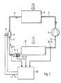
- the cooling device consists of compressor 1, line 2, condenser 3, line 4, expansion valve 5, which is clocked by a solenoid 6, line 7, venturi distributor 8, several lines 9, evaporator 10 and line 11.
- the air flowing through the condenser 3 cools it.
- the air flowing through the evaporator is cooled by the evaporator.
- the condenser is usually exposed to the wind, while the evaporator is traversed by the air to be cooled in the interior of a motor vehicle.
- the temperature sensor 20 is located in line 7 in front of the venturi distributor 8.
- the temperature sensor 21 is located on one of the lines 9 behind the venturi distributor 8.
- the lines 9 are all passed through the evaporator 10 after the refrigerant flow in the venturi distributor 8 has been divided into equal partial flows is.
- the temperature sensor 22 is located behind the evaporator 10, that is to say in front of the compressor 1.
- part of the refrigerant changes its physical state from the liquid to the gaseous phase, as a result of which the refrigerant cools to the lower temperature T2, the rest of the liquid phase evaporates in the evaporator 10 by removing heat from the surroundings, so that a temperature of 5 ° C can be given at the outlet of the evaporator at a pressure of about 3 bar.
- the solid and bell-like curve X drawn somewhat thicker than the other lines, describes the wet steam area, i.e. the area in which, under the condition conditions of the coolant defined thereby, it is present both in the vapor phase and in the liquid phase.
- Overheating refers to the fact that the temperature is higher than the temperature at which the coolant changes from the liquid phase to the gaseous phase. The greater the overheating, the safer the refrigerant is in the gaseous phase.
- a temperature must be given at the input of the compressor 1 which can be expected with certainty that the entire refrigerant is in the gaseous phase, that is to say has completely evaporated. Is this e.g. not the case, i.e. if the temperature is lower, this means that too much refrigerant has entered the evaporator.
- the expansion valve must e.g. controlled by clocking so that less refrigerant passes through. The temperature behind the evaporator or before the refrigerant enters the compressor then becomes correspondingly higher.
- the arrangement of the temperature sensors 20, 21, 22 is shown in FIG. 2 also designated by the reference numerals 20, 21, 22. Through these points in the cycle, the dashed isotherms T1, T2 and T3 go. It can be seen that, as mentioned, the temperature sensors 20, 21 are inside the curve X and the temperature sensors 22 are outside the curve X.
- the lower, dashed line in Figure 3 is undesirable because it provides a temperature T'3 too low.
- the upper of the two courses delivers a temperature T3, which is higher by the desired amount ⁇ tü.
- ⁇ tü can be calculated very reliably from the temperatures measured by the sensors 20, 21, 22 at the specified points using the following formula ⁇ tü-T3-T2 + k (T1-T2).
- k is a constant that depends on the design of the evaporator.
- the size k is determined in the manner already outlined and ultimately represents the ratio of the refrigerant-side pressure drop in the evaporator tube to the comparative pressure drop of the measuring orifice.
- the measuring point for T 1 and T 2 should be arranged such that the constant k is approximately 1 at least but within the limits 0.5 ⁇ k ⁇ 1.5.
- a corresponding control signal is, for example, a sequence of rectangular pulses of a certain length. The length and the distance of the rectangular pulses determine the temporal relationship between opening and closing of the expansion valve 5, so that the amount of coolant passing through the expansion valve is controlled in this way.
Landscapes
- Engineering & Computer Science (AREA)
- Physics & Mathematics (AREA)
- Mechanical Engineering (AREA)
- Thermal Sciences (AREA)
- General Engineering & Computer Science (AREA)
- Air-Conditioning For Vehicles (AREA)
Abstract
Description
Die Erfindung betrifft eine Vorrichtung zur Ansteuerung des Expansionsventils einer ferner Kompressor, Verdampfer und Kondensator aufweisenden Kälteeinrichtung in einem Kraftfahrzeug, bei der ein erster Temperaturfühler an einer ersten Stelle die Temperatur des Kältemittels in Strömungsrichtung hinter dem Verdampfer und ein zweiter Temperaturfühler an einer zweiten Stelle die Temperatur des Kältemittels in Strömunsrichtung vor dem Verdampfer mißt und daraus eine Stellgröße abgeleitet wird, die zur Einstellung des Expansionsventils derart dient, daß eine bestimmte vorzugebende Überhitzung des in Strömunsrichtung hinter dem Verdampfer in den Kompressor übertretenden Kältemittels gegeben ist.The invention relates to a device for controlling the expansion valve of a refrigeration device further comprising a compressor, evaporator and condenser in a motor vehicle, in which a first temperature sensor at a first point the temperature of the refrigerant downstream of the evaporator and a second temperature sensor at a second point the temperature of the refrigerant in the flow direction in front of the evaporator and a manipulated variable is derived therefrom, which is used to adjust the expansion valve in such a way that a specific one specified overheating of the refrigerant passing into the compressor downstream of the evaporator is given.
Derartige Vorrichtungen sind bekannt. In Abhängigkeit von den gemessenen Temperaturen regelt man das Expansionsventil derart, daß stets eine bestimmte, jedoch nicht übermäßige "optimale" Überhitzung des Kältemittels gegeben ist. Dies soll gewährleisten, daß dem in Strömungsrichtung folgenden Kompressor nur gasförmiges Kältemittel zugeführt wird, da ansonsten eine einwandfreie Funktion nicht gewährleistet wäre. Andererseits ist man aus Gründen eines optimalen Kreisprozesses daran interessiert, am Ausgang des Verdampfers möglichst wenig Überhitzung in Kauf nehmen zu müssen.Such devices are known. Depending on the measured temperatures, the expansion valve is controlled in such a way that there is always a certain, but not excessive, "optimal" overheating of the refrigerant. This is to ensure that only gaseous refrigerant is supplied to the compressor following in the direction of flow, since otherwise proper functioning would not be guaranteed. On the other hand, for reasons of an optimal cycle, one is interested in having to accept as little overheating as possible at the outlet of the evaporator.
Man könnte nun die Messung des Zustands des Kältemittels nach dem Verdampfer bzw. vor dem Kompressor dadurch zuverlässiger gestalten, daß man statt der Temperatur des Kältemittels vor dem Verdampfer den Druck des Kältemittels nach dem Verdampfer mißt und aus Temperatur und Druck die Stellgröße für das Expansionsventil ableitet. Druckmeßgeräte sind jedoch sehr viel teurer als Temperaturmeßgeräte.One could now make the measurement of the state of the refrigerant after the evaporator or before the compressor more reliable by measuring the pressure of the refrigerant after the evaporator instead of the temperature of the refrigerant before the evaporator and deriving the manipulated variable for the expansion valve from temperature and pressure . However, pressure gauges are much more expensive than temperature gauges.
Die seitherige Bestimmung des Zustands des Kältemittels bzw. seiner Überhitzung aufgrund der Temperaturmessungen vor und nach dem Verdampfer hat sich jedoch als unzuverlässig herausgestellt. Dies gilt insbesondere, wenn es sich um die Ansteuerung des Expansionsventils einer Kälteeinrichtung in einem Kraftfahrzeug handelt, dessen Betriebsparameter, insbesondere der Kältemitteldruck am Verdampferaustritt sich in Folge der ständigen Änderungen der Betriebsbedingungen des Kraftfahrzeuges, insbesondere der für die Leistung des Kompressors ausschlaggebenden Motordrehzahl, ständig ändern.However, the determination of the condition of the refrigerant or its overheating based on the temperature measurements before and after the evaporator has proven to be unreliable. This is especially true when it comes to the Actuation of the expansion valve of a refrigeration device in a motor vehicle, whose operating parameters, in particular the refrigerant pressure at the evaporator outlet, change constantly as a result of the constant changes in the operating conditions of the motor vehicle, in particular the engine speed which is decisive for the performance of the compressor.
Der Erfindung liegt demgemäß die Aufgabe zugrunde, die Bestimmung der Überhitzung des Kältemittels vor dem Eintritt in den Kompressor als Ausgangsgröße für die Ansteuerung des Expansionsventils einer Kälteeinrichtung in einem Kraftfahrzeug aufgrund von Temperaturmessungen zu verbessern.The invention is therefore based on the object of improving the determination of the superheating of the refrigerant before entering the compressor as an output variable for controlling the expansion valve of a refrigeration device in a motor vehicle on the basis of temperature measurements.
Erfindungsgemäß erfolgt die Lösung dieser Aufgabe dadurch, daß im Kältemittelkreislauf an einer weiteren Stelle ein weiterer Temperaturfühler angeordnet ist und die Temperatur des Kältemittels mißt, derart, daß sich zwei Temperaturfühler in allen Betriebszuständen im Naßdampfbereich befinden und zwischen ihnen ein Druckabfall stattfindet, und daß die Überhitzung des in den Kompressor übertretenden Kältemittels aus den mit den insgesamt drei Temperaturfühlern bestimmten Temperaturen bestimmt und daraus die Stellgröße für das Expansionsventil abgeleitet wird.According to the invention, this object is achieved in that a further temperature sensor is arranged at a further point in the refrigerant circuit and measures the temperature of the refrigerant, such that two temperature sensors are in the wet steam range in all operating states and there is a pressure drop between them, and that the overheating occurs of the refrigerant flowing into the compressor is determined from the temperatures determined with the three temperature sensors and the manipulated variable for the expansion valve is derived.
Die Angabe, daß die insgesamt zwei Temperaturfühler an Stellen angeordnet sein sollen, zwischen denen ein Druckabfall stattfindet und die in allen Betriebszuständen im Naßdampfbereich liegen, sichert, daß stets Sättigungstemperaturen gemessen werden. Der Naßdampfbereich ist bekanntlich im Enthalpie-Druck-Diagramm der glockenförmige Bereich, innerhalb dessen das Kältemittel als 2-Phasensystem, also sowohl als Dampf als auch als Flüssigkeit anwesend ist.The indication that a total of two temperature sensors should be arranged at locations between which there is a pressure drop and which in all operating conditions in the Wet steam range ensures that saturation temperatures are always measured. As is known, in the enthalpy-pressure diagram, the wet steam area is the bell-shaped area within which the refrigerant is present as a two-phase system, that is to say both as a vapor and as a liquid.
Die beiden Stellen können im Prinzip entlang der Stranglänge des Verdampfers oder zwischen dem Expansionsventil und dem Verdampfer angeordnet sein, soweit zwischen ihnen ein gewisser Druckabfall gegeben ist, also zum Beispiel auch vor und hinter der Wirbelzelle und/oder dem Venturiverteiler angeordnet sein. An beiden tritt Druckabfall auf. Als besonders vorteilhaft hat sich dabei die Anordnung in Strömungsrichtung vor und hinter dem Venturiverteiler erwiesen. Der Venturiverteiler, der den zum Verdampfer strömenden Kältemittelstrom auf mehrere Verdampferrohre aufteilt, wirkt praktisch wie eine Meßblende.In principle, the two points can be arranged along the length of the evaporator or between the expansion valve and the evaporator, provided that there is a certain pressure drop between them, for example also in front of and behind the vortex cell and / or the venturi distributor. Pressure drop occurs at both. The arrangement in the flow direction upstream and downstream of the venturi distributor has proven to be particularly advantageous. The venturi distributor, which divides the refrigerant flow flowing to the evaporator over several evaporator tubes, acts practically like a measuring orifice.
Die rechnerische Ermittlung der Überhitzung nach dem Verdampfer oder vor dem Kompressor, auf deren genaue Steuerung durch Einstellung des Expansionsventil es ankommt, erfolgt bei der Messung von Temperaturen an drei Stellen, die den angegebenen Bedingungen genügen, derart, daß die Überhitzung (Δtü) aus den mittels der drei Temperaturfühler gemessenen Temperaturen (T₁, T₂, T₃) in einer Recheneinheit nach der Formel
Δtü=T₃-T₂=k(T₁-T₂) (1)
berechnet wird, wobei k eine Verdampfer-spezifische Konstante ist, die einmalig experimentiell nach der Beziehung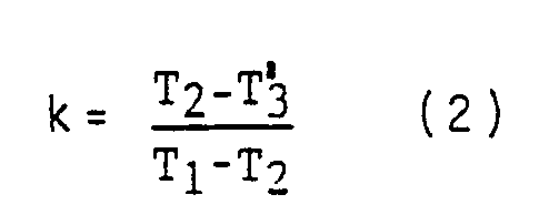
Δtü = T₃-T₂ = k (T₁-T₂) (1)
is calculated, where k is an evaporator-specific constant that is unique experimentally according to the relationship
Ein Ausführungsbeispiel der Erfingung und ihrer vorteilhaften Weiterbildungen wird im folgenden anhand der beigefügten Zeichnungen beschrieben. Es stellen dar
- Figur 1 den Kältemittelkreislauf einer Kühleinrichtung in einem Kraftfahrzeug mit den zugeordneten Meß- und Steuerungseinrichtungen;
Figur 2 den realen Verlauf des Kreisprozesses im Enthalpie-Druck-Diagramm und- Figur 3 den Verlauf der Temperatur vor und entlang der Stranglänge des Verdampfers.
- 1 shows the refrigerant circuit of a cooling device in a motor vehicle with the associated measuring and control devices;
- Figure 2 shows the real course of the cycle in the enthalpy-pressure diagram and
- 3 shows the course of the temperature before and along the length of the evaporator.
Die Kälteeinrichtung nach Figur 1 besteht aus Kompressor 1, Leitung 2, Kondensator 3, Leitung 4, Expansionsventil 5, das von einer Magnetspule 6 getaktet wird, Leitung 7, Venturiverteiler 8, mehreren Leitungen 9, Verdampfer 10 und Leitung 11. Wie durch die eingezeichneten Pfeile angedeutet, werden sowohl der Kondensator 3 wie auch der Verdampfer 10 von Luft durchströmt. Die den Kondensator 3 durchströmende Luft kühlt diesen. Andererseits wird die durch den Verdampfer hindurchströmende Luft von dem Verdampfer gekühlt. Der Kondensator ist meist dem Fahrtwind ausgesetzt, während der Verdampfer von der zu kühlenden Luft im Innenraum eines Kraftfahrzeugs durchströmt wird.The cooling device according to Figure 1 consists of compressor 1,
Entlang des Kältemittelkreislaufs sind drei Temperaturfühler 20, 21, 22 angeordnet, die die Temperaturen T₁, T₂, T₃ messen. Der Temperaturfühler 20 befindet sich in Leitung 7 vor dem Venturiverteiler 8. Der Temperaturfühler 21 befindet sich an einer der Leitungen 9 hinter dem Venturiverteiler 8. Die Leitungen 9 sind sämtlich durch den Verdampfer 10 hindurchgeführt, nachdem in Venturiverteiler 8 der Kältemittelstrom in gleiche Teilströme aufgeteilt worden ist. Der Temperaturfühler 22 befindet sich hinter dem Verdampfer 10, also vor dem Kompressor 1.Along the refrigerant circuit, three
Der Verlauf von Druck und Temperatur an den einzelnen Punkten des Kältemittelkreislaufs ergibt sich aus der Darstellung des Kreisprozesses in Figur 2, wobei an den einzelnen Geraden die Bezugszeichen angebracht sind, die denjenigen Baueinheiten nach Figur 1 entsprechen, in denen sich die durch die Geraden dargestellten Zustandsänderungen vollziehen. Die folgenden Angaben dienen der Erläuterung dieses Kreisprozesses, sind jedoch ausdrücklich lediglich beispielhaft zu verstehen:The course of pressure and temperature at the individual points of the refrigerant circuit results from the illustration of the cycle in FIG. 2, the reference numerals being attached to the individual straight lines, which correspond to those structural units according to FIG. 1 in which the changes in state represented by the straight lines are shown perform. The following information serves to explain this cycle process, but is only to be understood as an example:
Am Ende von Leitung 11 herrscht z.B. ein Druck von 2,5 bar bei 8°C. Im Kompressor wird der Druck auf 18 bar bei 100°C erhöht. In Leitung 2 sowie im Kondensator 3 wird die Temperatur abgesenkt und das Kältemittel in die flüssige Phase übergeführt, wobei sich ein geringfügiger Druckabfall ergibt. Am Anfang von Leitung 4 ist z.B. 16 bar bei 55°C gegeben. Im Expansionsventil 5 und in der sich anschließenden Leitung 7 fällt der Druck sehr stark ab. Gleichzeitig ändert in Folge des abgefallenen Drucks ein Teil des Kältemittels seinen Aggregatzustand von der flüssigen in die gasförmige Phase, wodurch sich das Kältemittel auf die tiefere Temperatur T₂, abkühlt, der Rest der flüssigen Phase verdampft im Verdampfer 10, indem der Umgebung Wärme entzogen wird, so daß am Ausgang des Verdampfers bei einem Druck von ca. 3 bar eine Temperatur von 5°C gegeben sein kann.At the end of
Die etwas dicker als die übrigen Linien gezeichnete durchgezogene und glockenartige Kurve X umschreibt den Naßdampfbereich, d.h. den Bereich, in dem bei den dadurch definierten Zustandsbedingungen des Kühlmittels dieses sowohl in der Phase Dampf als auch in der Phase Flüssigkeit vorhanden ist.The solid and bell-like curve X, drawn somewhat thicker than the other lines, describes the wet steam area, i.e. the area in which, under the condition conditions of the coolant defined thereby, it is present both in the vapor phase and in the liquid phase.
Von großer Bedeutung für das richtige Funktionieren des Kompressors 1 ist, daß vor seinem Eingang eine gewisse Überhitzung Δtü gegeben ist. Als Überhitzung bezeichnet man damit die Tatsache, daß die Temperatur höher ist als die Temperatur, bei der das Kühlmittel von der flüssigen Phase in die gasförmige Phase übergeht. Je größer die Überhitzung ist, desto sicherer befindet sich das Kältemittel in gasförmiger Phase. Aus gründen der Betriebssicherheit muß am Eingang des Kompressors 1 eine Temperatur gegeben sein, die mit Sicherheit erwarten läßt, daß sich das gesamte Kältemittel in der gasförmigen Phase befindet, also vollständig verdampft ist. Ist dies z.B. nicht der Fall, d.h. ist die Temperatur niedriger, so bedeutet dies, daß zuviel Kältemittel in den Verdampfer gelangt ist. Das Expansionsventil muß also z.B. durch Takten so angesteuert werden, daß weniger Kältemittel hindurchtritt. Die Temperatur hinter dem Verdampfer bzw. vor dem Eintritt des Kältemittels in den Kompressor wird dann entsprechend höher.Of great importance for the correct functioning of the compressor 1 is that there is a certain overheating Δtü before its input. Overheating refers to the fact that the temperature is higher than the temperature at which the coolant changes from the liquid phase to the gaseous phase. The greater the overheating, the safer the refrigerant is in the gaseous phase. For reasons of operational safety, a temperature must be given at the input of the compressor 1 which can be expected with certainty that the entire refrigerant is in the gaseous phase, that is to say has completely evaporated. Is this e.g. not the case, i.e. if the temperature is lower, this means that too much refrigerant has entered the evaporator. The expansion valve must e.g. controlled by clocking so that less refrigerant passes through. The temperature behind the evaporator or before the refrigerant enters the compressor then becomes correspondingly higher.
Die Anordnung der Temperaturfühler 20, 21, 22 ist in Figur 2 ebenfalls mit den Bezugszeichen 20, 21, 22 bezeichnet. Durch diese Punkte im Kreisprozeß gehen die gestrichelt eingezeichneten Isothermen T₁, T₂ und T₃. Es ist ersichtlich, daß, wie erwähnt, sich die Temperaturfühler 20, 21 innerhalb der Kurve X, und der Temperaturfühler 22 außerhalb der Kurve X befinden.The arrangement of the
Der untere, gestrichelt gezeichnete Verlauf in Figur 3 ist unerwünscht, weil er eine zu niedrige Temperatur T′₃ liefert. Der obere der beiden Verlaufe liefert eine Temperatur T₃, die um den gewünschten Betrag Δtü höher liegt.The lower, dashed line in Figure 3 is undesirable because it provides a temperature T'₃ too low. The upper of the two courses delivers a temperature T₃, which is higher by the desired amount Δtü.
Es hat sich nun herausgestellt, daß die Temperatur Δtü aus den durch die Fühler 20, 21, 22 an den angegebenen Stellen gemessenen Temperaturen sehr zuverlässig nach folgender Formel berechnet werden kann
Δtü-T₃-T₂+k(T₁-T₂).
k ist eine Konstante, die vom konstruktiven Aufbau des Verdampfers abhängt. Die Größe k wird in der bereits eingangs dargestellten Weise ermittelt und stellt letztlich das Verhältnis des kältemittelseitigen Druckabfalls im Verdampferrohr zum Vergleichsdruckabfall der Meßblende dar. Im Hinblick auf ausreichende Meßgenauigkeit sollte die Meßstelle für T₁ und T₂ so angeordnet sein, daß die Konstante k ungefähr 1 mindestens aber in den Grenzen 0,5 ≦ k ≦ 1,5 ist. Sie wird für jede der bestimmten Kühleinrichtung experimentell ermittelt und dann der Berechnung von Δtü zugrundegelegt. Die Berechnung erfolgt in der Recheneinheit 30 (vgl. Figur 1), an die die mittels Temperaturfühler 20 bis 22 gemessenen Temperaturen T₁ bis T₃ gelangen. In der Recheneinheit 30 wird dann eine Stellgröße y=f(Δtü) abgeleitet. Ein entsprechendes Steuersignal ist z.B. eine Folge von Rechteckimpulsen bestimmter Länge. Die Länge und der Abstand der Rechteckimpulse bestimmt das zeitliche Verhältnis von Öffnung und Schließung des Expansionsventils 5, so daß derart die Menge des durch das Expansionsventil hindurchtretenden Kühlmittels gesteuert wird.It has now been found that the temperature Δtü can be calculated very reliably from the temperatures measured by the
Δtü-T₃-T₂ + k (T₁-T₂).
k is a constant that depends on the design of the evaporator. The size k is determined in the manner already outlined and ultimately represents the ratio of the refrigerant-side pressure drop in the evaporator tube to the comparative pressure drop of the measuring orifice. With regard to sufficient measuring accuracy, the measuring point for T 1 and
Claims (3)
Δtü=T₃-T₂+k(T₁-T₂)
berechnet wird, wobei k eine Verdampfer-spezifische Konstante ist.3. Apparatus according to claim 1, characterized in that the overheating (Δtü) from the measured by means of the three temperature sensors (20,21,22) temperatures (T₁, T₂, T₃) in a computing unit (30) according to the formula
Δtü = T₃-T₂ + k (T₁-T₂)
is calculated, where k is an evaporator-specific constant.
Applications Claiming Priority (2)
| Application Number | Priority Date | Filing Date | Title |
|---|---|---|---|
| DE19873743285 DE3743285A1 (en) | 1987-12-19 | 1987-12-19 | DEVICE FOR CONTROLLING THE EXPANSION VALVE OF THE REFRIGERATION DEVICE IN A MOTOR VEHICLE AIR CONDITIONING |
| DE3743285 | 1987-12-19 |
Publications (3)
| Publication Number | Publication Date |
|---|---|
| EP0321670A2 true EP0321670A2 (en) | 1989-06-28 |
| EP0321670A3 EP0321670A3 (en) | 1990-05-23 |
| EP0321670B1 EP0321670B1 (en) | 1992-07-22 |
Family
ID=6343106
Family Applications (1)
| Application Number | Title | Priority Date | Filing Date |
|---|---|---|---|
| EP88117426A Expired - Lifetime EP0321670B1 (en) | 1987-12-19 | 1988-10-19 | Expansion valve control device for the refrigerating appliance of a motor vehicle air conditioning equipment |
Country Status (2)
| Country | Link |
|---|---|
| EP (1) | EP0321670B1 (en) |
| DE (2) | DE3743285A1 (en) |
Cited By (4)
| Publication number | Priority date | Publication date | Assignee | Title |
|---|---|---|---|---|
| US5186021A (en) * | 1991-05-20 | 1993-02-16 | Carrier Corporation | Bypass expansion device having defrost optimization mode |
| WO1996012148A1 (en) * | 1994-10-15 | 1996-04-25 | Danfoss A/S | Control arrangement for the superheat temperature of at least one evaporator of a refrigeration system |
| CN100545551C (en) * | 2007-01-24 | 2009-09-30 | 三星电子株式会社 | The degree of superheat control system and the method thereof of air conditioner |
| EP2137471A4 (en) * | 2006-12-29 | 2015-05-06 | Carrier Corp | Air-conditioning control algorithm employing air and fluid inputs |
Families Citing this family (1)
| Publication number | Priority date | Publication date | Assignee | Title |
|---|---|---|---|---|
| EP4079549B1 (en) * | 2021-04-21 | 2024-04-24 | Ningbo Geely Automobile Research & Development Co., Ltd. | A method for controlling a refrigeration system of a vehicle |
Citations (7)
| Publication number | Priority date | Publication date | Assignee | Title |
|---|---|---|---|---|
| GB639683A (en) * | 1947-11-07 | 1950-07-05 | J & E Hall Ltd | Improvements in apparatus for the control of expansion valves of refrigerators |
| US3478534A (en) * | 1967-08-11 | 1969-11-18 | Controls Co Of America | Thermistor controlled refrigeration expansion valve |
| US3538717A (en) * | 1968-12-04 | 1970-11-10 | Controls Co Of America | Refrigeration system control arrangement including heat motor operated expansion valve |
| EP0133512A2 (en) * | 1983-08-06 | 1985-02-27 | Joh. Vaillant GmbH u. Co. | Refrigerant flow control for a heat pump |
| US4617804A (en) * | 1985-01-30 | 1986-10-21 | Hitachi, Ltd. | Refrigerant flow control device |
| US4653288A (en) * | 1984-07-02 | 1987-03-31 | Hitachi, Ltd. | Apparatus for measuring refrigerant flow rate in refrigeration cycle |
| US4689968A (en) * | 1986-03-21 | 1987-09-01 | Danfoss A/S | Actuator means for the control of a refrigeration system expansion valve |
Family Cites Families (6)
| Publication number | Priority date | Publication date | Assignee | Title |
|---|---|---|---|---|
| US3659783A (en) * | 1969-10-24 | 1972-05-02 | Eaton Yale & Towne | Temperature regulated flow control element for automotive air-conditioners |
| DE2530021C3 (en) * | 1975-07-04 | 1980-07-31 | Fiat S.P.A., Turin (Italien) | Control valve for a cooling system of a motor vehicle |
| CA1087412A (en) * | 1976-03-04 | 1980-10-14 | Charles D. Orth | High side pressure limiting thermostatic expansion valve |
| DE3220420A1 (en) * | 1982-05-29 | 1983-12-15 | Vereinigte Elektrizitätswerke Westfalen AG, 4600 Dortmund | Process for the regulation of an electrically controllable expansion valve |
| JPS61256153A (en) * | 1985-05-08 | 1986-11-13 | 株式会社豊田自動織機製作所 | Air conditioner for car |
| DE3601817A1 (en) * | 1986-01-22 | 1987-07-23 | Egelhof Fa Otto | CONTROL DEVICE FOR THE REFRIGERANT FLOW FOR EVAPORATING REFRIGERATION SYSTEMS OR HEAT PUMPS AND EXPANSION VALVES ARRANGED IN THE REFRIGERANT FLOW |
-
1987
- 1987-12-19 DE DE19873743285 patent/DE3743285A1/en not_active Withdrawn
-
1988
- 1988-10-19 EP EP88117426A patent/EP0321670B1/en not_active Expired - Lifetime
- 1988-10-19 DE DE8888117426T patent/DE3873055D1/en not_active Expired - Fee Related
Patent Citations (7)
| Publication number | Priority date | Publication date | Assignee | Title |
|---|---|---|---|---|
| GB639683A (en) * | 1947-11-07 | 1950-07-05 | J & E Hall Ltd | Improvements in apparatus for the control of expansion valves of refrigerators |
| US3478534A (en) * | 1967-08-11 | 1969-11-18 | Controls Co Of America | Thermistor controlled refrigeration expansion valve |
| US3538717A (en) * | 1968-12-04 | 1970-11-10 | Controls Co Of America | Refrigeration system control arrangement including heat motor operated expansion valve |
| EP0133512A2 (en) * | 1983-08-06 | 1985-02-27 | Joh. Vaillant GmbH u. Co. | Refrigerant flow control for a heat pump |
| US4653288A (en) * | 1984-07-02 | 1987-03-31 | Hitachi, Ltd. | Apparatus for measuring refrigerant flow rate in refrigeration cycle |
| US4617804A (en) * | 1985-01-30 | 1986-10-21 | Hitachi, Ltd. | Refrigerant flow control device |
| US4689968A (en) * | 1986-03-21 | 1987-09-01 | Danfoss A/S | Actuator means for the control of a refrigeration system expansion valve |
Cited By (4)
| Publication number | Priority date | Publication date | Assignee | Title |
|---|---|---|---|---|
| US5186021A (en) * | 1991-05-20 | 1993-02-16 | Carrier Corporation | Bypass expansion device having defrost optimization mode |
| WO1996012148A1 (en) * | 1994-10-15 | 1996-04-25 | Danfoss A/S | Control arrangement for the superheat temperature of at least one evaporator of a refrigeration system |
| EP2137471A4 (en) * | 2006-12-29 | 2015-05-06 | Carrier Corp | Air-conditioning control algorithm employing air and fluid inputs |
| CN100545551C (en) * | 2007-01-24 | 2009-09-30 | 三星电子株式会社 | The degree of superheat control system and the method thereof of air conditioner |
Also Published As
| Publication number | Publication date |
|---|---|
| EP0321670B1 (en) | 1992-07-22 |
| DE3873055D1 (en) | 1992-08-27 |
| EP0321670A3 (en) | 1990-05-23 |
| DE3743285A1 (en) | 1989-06-29 |
Similar Documents
| Publication | Publication Date | Title |
|---|---|---|
| DE2950264C2 (en) | ||
| DE4213011C2 (en) | Coolant circuit with control of an economy device | |
| DE3012686C2 (en) | Device for regulating the superheating temperature at the evaporator outlet of a reversible refrigeration machine | |
| DE69730613T2 (en) | MODULATING LIQUID RATE DEVICE | |
| EP0411172A1 (en) | Refrigeration device for a plurality of coolant circuits | |
| DE3713869A1 (en) | CONTROL UNIT FOR THE OVERHEATING TEMPERATURE OF THE EVAPORATOR OF A REFRIGERATION OR HEAT PUMP SYSTEM | |
| EP0559043B1 (en) | Method for heat exchanger control | |
| DE2822389A1 (en) | HEAT CONTENT COMPARISON | |
| DE4436925C2 (en) | Control device for the superheating temperature of at least one evaporator of a refrigeration system | |
| DE3413535C1 (en) | Measuring device for determining a proportion of liquid in the refrigerant | |
| DE102005048967B4 (en) | Method for operating a compression refrigeration system | |
| EP1920954B1 (en) | Method for regulating a motor vehicle air-conditioning system with at least two evaporators | |
| EP0321670A2 (en) | Expansion valve control device for the refrigerating appliance of a motor vehicle air conditioning equipment | |
| DE3722000C2 (en) | Device for measuring the temperature of a medium, in particular for measuring the interior temperature in a motor vehicle | |
| DE69728012T2 (en) | Absorption over-concentration control | |
| EP0164382B1 (en) | Resorption thermal conversion plant | |
| DE60309181T2 (en) | METHOD AND DEVICE FOR DISCOVERING FLASH GAS | |
| DE4139064C2 (en) | Method for monitoring the filling level of a refrigerant evaporator | |
| WO2016055162A1 (en) | Method for controlling a coupled heat exchanger system and heat-exchanger system | |
| EP0239842B1 (en) | Method for regulating interior temperature, especially that of a motor vehicle | |
| DE10130986A1 (en) | Method for detecting a refrigerant loss in a refrigerant circuit and refrigeration or air conditioning | |
| DE102004005802B4 (en) | Method for controlling a refrigeration machine according to the evaporator principle and arrangement for carrying out the method | |
| DE3113697C2 (en) | ||
| DE4126054C2 (en) | Refrigerant consumption measuring system | |
| DE814052C (en) | Calorimetric steam flow meter |
Legal Events
| Date | Code | Title | Description |
|---|---|---|---|
| PUAI | Public reference made under article 153(3) epc to a published international application that has entered the european phase |
Free format text: ORIGINAL CODE: 0009012 |
|
| AK | Designated contracting states |
Kind code of ref document: A2 Designated state(s): DE ES FR GB IT SE |
|
| PUAL | Search report despatched |
Free format text: ORIGINAL CODE: 0009013 |
|
| AK | Designated contracting states |
Kind code of ref document: A3 Designated state(s): DE ES FR GB IT SE |
|
| RAP1 | Party data changed (applicant data changed or rights of an application transferred) |
Owner name: BEHR GMBH & CO. |
|
| 17P | Request for examination filed |
Effective date: 19900809 |
|
| 17Q | First examination report despatched |
Effective date: 19910221 |
|
| GRAA | (expected) grant |
Free format text: ORIGINAL CODE: 0009210 |
|
| AK | Designated contracting states |
Kind code of ref document: B1 Designated state(s): DE ES FR GB IT SE |
|
| PG25 | Lapsed in a contracting state [announced via postgrant information from national office to epo] |
Ref country code: IT Free format text: LAPSE BECAUSE OF FAILURE TO SUBMIT A TRANSLATION OF THE DESCRIPTION OR TO PAY THE FEE WITHIN THE PRE;WARNING: LAPSES OF ITALIAN PATENTS WITH EFFECTIVE DATE BEFORE 2007 MAY HAVE OCCURRED AT ANY TIME BEFORE 2007. THE CORRECT EFFECTIVE DATE MAY BE DIFFERENT FROM THE ONE RECORDED.SCRIBED TIME-LIMIT Effective date: 19920722 Ref country code: ES Free format text: THE PATENT HAS BEEN ANNULLED BY A DECISION OF A NATIONAL AUTHORITY Effective date: 19920722 Ref country code: SE Effective date: 19920722 Ref country code: GB Effective date: 19920722 |
|
| REF | Corresponds to: |
Ref document number: 3873055 Country of ref document: DE Date of ref document: 19920827 |
|
| ET | Fr: translation filed | ||
| GBV | Gb: ep patent (uk) treated as always having been void in accordance with gb section 77(7)/1977 [no translation filed] |
Effective date: 19920722 |
|
| PLBE | No opposition filed within time limit |
Free format text: ORIGINAL CODE: 0009261 |
|
| STAA | Information on the status of an ep patent application or granted ep patent |
Free format text: STATUS: NO OPPOSITION FILED WITHIN TIME LIMIT |
|
| 26N | No opposition filed | ||
| PGFP | Annual fee paid to national office [announced via postgrant information from national office to epo] |
Ref country code: FR Payment date: 19981020 Year of fee payment: 11 |
|
| PGFP | Annual fee paid to national office [announced via postgrant information from national office to epo] |
Ref country code: DE Payment date: 19981023 Year of fee payment: 11 |
|
| PG25 | Lapsed in a contracting state [announced via postgrant information from national office to epo] |
Ref country code: FR Free format text: LAPSE BECAUSE OF NON-PAYMENT OF DUE FEES Effective date: 20000630 |
|
| PG25 | Lapsed in a contracting state [announced via postgrant information from national office to epo] |
Ref country code: DE Free format text: LAPSE BECAUSE OF NON-PAYMENT OF DUE FEES Effective date: 20000801 |
|
| REG | Reference to a national code |
Ref country code: FR Ref legal event code: ST |