EP0321437A2 - Method for the manufacture of a single- or double-edged press knife for nonmetallic materials - Google Patents
Method for the manufacture of a single- or double-edged press knife for nonmetallic materials Download PDFInfo
- Publication number
- EP0321437A2 EP0321437A2 EP88890286A EP88890286A EP0321437A2 EP 0321437 A2 EP0321437 A2 EP 0321437A2 EP 88890286 A EP88890286 A EP 88890286A EP 88890286 A EP88890286 A EP 88890286A EP 0321437 A2 EP0321437 A2 EP 0321437A2
- Authority
- EP
- European Patent Office
- Prior art keywords
- knife
- reinforcing plate
- groove
- punching
- plate
- Prior art date
- Legal status (The legal status is an assumption and is not a legal conclusion. Google has not performed a legal analysis and makes no representation as to the accuracy of the status listed.)
- Ceased
Links
Images

Classifications
-
- B—PERFORMING OPERATIONS; TRANSPORTING
- B21—MECHANICAL METAL-WORKING WITHOUT ESSENTIALLY REMOVING MATERIAL; PUNCHING METAL
- B21D—WORKING OR PROCESSING OF SHEET METAL OR METAL TUBES, RODS OR PROFILES WITHOUT ESSENTIALLY REMOVING MATERIAL; PUNCHING METAL
- B21D37/00—Tools as parts of machines covered by this subclass
- B21D37/20—Making tools by operations not covered by a single other subclass
- B21D37/205—Making cutting tools
-
- B—PERFORMING OPERATIONS; TRANSPORTING
- B23—MACHINE TOOLS; METAL-WORKING NOT OTHERWISE PROVIDED FOR
- B23P—METAL-WORKING NOT OTHERWISE PROVIDED FOR; COMBINED OPERATIONS; UNIVERSAL MACHINE TOOLS
- B23P15/00—Making specific metal objects by operations not covered by a single other subclass or a group in this subclass
- B23P15/28—Making specific metal objects by operations not covered by a single other subclass or a group in this subclass cutting tools
- B23P15/40—Making specific metal objects by operations not covered by a single other subclass or a group in this subclass cutting tools shearing tools
-
- B—PERFORMING OPERATIONS; TRANSPORTING
- B26—HAND CUTTING TOOLS; CUTTING; SEVERING
- B26F—PERFORATING; PUNCHING; CUTTING-OUT; STAMPING-OUT; SEVERING BY MEANS OTHER THAN CUTTING
- B26F1/00—Perforating; Punching; Cutting-out; Stamping-out; Apparatus therefor
- B26F1/38—Cutting-out; Stamping-out
- B26F1/44—Cutters therefor; Dies therefor
- B26F1/46—Loose press knives
-
- B—PERFORMING OPERATIONS; TRANSPORTING
- B26—HAND CUTTING TOOLS; CUTTING; SEVERING
- B26F—PERFORATING; PUNCHING; CUTTING-OUT; STAMPING-OUT; SEVERING BY MEANS OTHER THAN CUTTING
- B26F1/00—Perforating; Punching; Cutting-out; Stamping-out; Apparatus therefor
- B26F1/38—Cutting-out; Stamping-out
- B26F1/40—Cutting-out; Stamping-out using a press, e.g. of the ram type
-
- B—PERFORMING OPERATIONS; TRANSPORTING
- B26—HAND CUTTING TOOLS; CUTTING; SEVERING
- B26F—PERFORATING; PUNCHING; CUTTING-OUT; STAMPING-OUT; SEVERING BY MEANS OTHER THAN CUTTING
- B26F1/00—Perforating; Punching; Cutting-out; Stamping-out; Apparatus therefor
- B26F1/38—Cutting-out; Stamping-out
- B26F1/44—Cutters therefor; Dies therefor
- B26F2001/4463—Methods and devices for rule setting, fixation, preparing cutting dies
-
- Y—GENERAL TAGGING OF NEW TECHNOLOGICAL DEVELOPMENTS; GENERAL TAGGING OF CROSS-SECTIONAL TECHNOLOGIES SPANNING OVER SEVERAL SECTIONS OF THE IPC; TECHNICAL SUBJECTS COVERED BY FORMER USPC CROSS-REFERENCE ART COLLECTIONS [XRACs] AND DIGESTS
- Y10—TECHNICAL SUBJECTS COVERED BY FORMER USPC
- Y10T—TECHNICAL SUBJECTS COVERED BY FORMER US CLASSIFICATION
- Y10T83/00—Cutting
- Y10T83/929—Tool or tool with support
- Y10T83/9295—Work supported tool [e.g., clicker die]
Definitions
- the invention relates to a method for producing a one- or two-sided punching knife for non-metallic materials, such as leather, textiles, paper etc. with an internal groove and a reinforcing plate engaging in the groove, and a steel strip for carrying out the method.
- Punch knives of the type to be manufactured are known from DE-OS 1 511 073 and US Pat. No. 2,298,041. For example, they are bent from steel strip, possibly around the finished reinforcement plate.
- the reinforcement plates made of wood, cardboard, plastic or metal are manufactured in a suitable manner, for example by sawing, then inserted into the knife - or the knife is bent around them - and connected to it.
- Punching knives are also known which have no reinforcing plates but instead have rod-shaped stiffening elements in the interior of the knife.
- the attachment of the reinforcing bars, usually by welding, is at least as complex and time-consuming as the insertion of a reinforcing plate.
- the latter has the advantage of stiffening and supporting the punch knife evenly over the entire circumference.
- the invention has set itself the task of specifying a manufacturing method for a punching knife of the type mentioned at the outset which is simple and inexpensive to carry out. It should also be possible to use various fittings such as perforated pipes, inner knives, seam sign lines and marking mandrels without a large area easy and permanent to arrange work effort in the reinforcement plate.
- the reinforcing plate is made of non-metallic material, preferably plastic, its thickness at least approximately equal to the width of the groove, and in which it is punched out by the knife which it is intended to reinforce.
- the ends of the knife are connected (welded) to one another and the knife is connected to the reinforcing plate, for example by screwing, soldering or welding.
- customary internals such as perforated pipes, inner knives, seam sign lines and marking pins, are punched into the reinforcing plate, advantageously after it has been pressed into the knife, optionally after predrilling.
- punching knife obtained according to the invention that the installation of such internals is possible easily and inexpensively by means of a punching process.
- the idea of punching in accordance with the invention is used, while for installations without cutting edges, the reinforcement is generally predrilled kungsplatte is necessary.
- Internals are used which have a groove on the side facing the reinforcing plate, which advantageously corresponds to the groove of the knife.
- the method according to the invention for producing a punching knife is carried out in such a way that the finished bent knife, which is possibly closed at its ends, is placed on a solid base, that a plate made of the material from which the reinforcing plate is to be arranged is arranged above the knife and by means of is punched into the knife in the conventional punching technology, the reinforcing plate coming to rest in the groove.
- Steel strip is preferably used for the knife, which can easily be brought into the desired shape using conventional methods. It is advantageous to use a steel strip which already has the cutting edge (s) and the groove before bending.
- Plastic plates for example made of polyolefin, polyethylene or acrylic, are preferably used as reinforcing plates.
- Such plates have a Shore hardness D of 75, which, when using a 19 mm high and 2.3 mm thick punching knife, a plate thickness of 4 mm and a plate size of approximately 100 x 50 mm, is press-fit force of 45 kN.
- the press-in force depends primarily on the length, but also on the area and shape of the knife.
- FIG. 1 shows a punch knife according to the invention before punching the reinforcing plate
- FIG. 2 shows a punch knife after punching the reinforcing plate
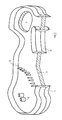
- FIG. 3 shows a finished punch knife with internals, partly in section.
- a plate 3 ' from which the reinforcing plate 3 is to be punched, lies above the knife 1. This plate is pressed against the knife 1 by devices customary in the stamping industry and finally reaches the position shown in FIG. 2.
- the reinforcing plate 3 sits with its punched-out edges in the groove 4 and is held by it.
- the punch knife is thus completed in one operation, but can be further stiffened by connecting the knife to the reinforcing plate. It is necessary to connect the knife ends to one another before punching the reinforcing plate, preferably to weld.
- Fig. 3 is a punch knife according to the invention with some internals, some. in section.
- the internals are two perforated pipes 6 and a series of marking mandrels 5 which form a seam sign line.
- An inner knife 8 is shown in section, whereby its groove is visible in the area of the reinforcing plate 3.
- an opening 7 is further provided in the reinforcing plate 3 through which the weight of the punch knife is reduced and its handling is facilitated. This opening also facilitates the removal of the punched-out material from the knife.
- the method according to the invention can be modified in various ways. It is therefore not necessary for the plate to be pressed in from above, and the reinforcement plate can also have been provided with the internals before the punching, if desired. Especially when using stronger reinforcement plates, it is possible to press against the knife with a pressure device, which is also provided with a cutting edge (opposite the knife edge or offset to the knife edge) in order to facilitate the cutting process.
- the invention also relates to punch knives which have been produced by the method according to the invention.
Landscapes
- Engineering & Computer Science (AREA)
- Mechanical Engineering (AREA)
- Life Sciences & Earth Sciences (AREA)
- Forests & Forestry (AREA)
- Perforating, Stamping-Out Or Severing By Means Other Than Cutting (AREA)
Abstract
Die Erfindung betrifft ein Verfahren zur Herstellung eines ein- oder zweiseitigen Stanzmessers (1) für nichtmetallische Werkstoffe, wie Leder, Textilien, Papier etc. mit einer innenliegenden Nut (4) und einer in die Nut eingreifenden Verstärkungsplatte (3). Erfindungsgemäß ist dabei vorgesehen, daß die Verstärkungsplatte (3) aus nichtmetallischem Werkstoff besteht und von dem Messer (1), das sie verstärken soll, ausgestanzt wird.The invention relates to a method for producing a one- or two-sided punching knife (1) for non-metallic materials, such as leather, textiles, paper, etc., with an internal groove (4) and a reinforcing plate (3) engaging in the groove. According to the invention, it is provided that the reinforcing plate (3) consists of non-metallic material and is punched out by the knife (1) which it is intended to reinforce.
Description
Die Erfindung betrifft ein Verfahren zur Herstellung eines ein- oder zweiseitigen Stanzmessers für nichtmetallische Werkstoffe, wie Leder, Textilien, Papier etc. mit einer innenliegenden Nut und einer in die Nut eingreifenden Verstärkungsplatte, sowie einen Bandstahl zur Durchführung des Verfahrens.The invention relates to a method for producing a one- or two-sided punching knife for non-metallic materials, such as leather, textiles, paper etc. with an internal groove and a reinforcing plate engaging in the groove, and a steel strip for carrying out the method.
Aus der DE-OS 1 511 073 und der US-PS 2 298 041 sind Stanzmesser der herzustellenden Art bekannt. Sie werden beispielsweise aus Bandstahl, gegebenenfalls um die fertige Verstärkungsplatte herum, gebogen. Die Verstärkungsplatten aus Holz, Karton, Kunststoff oder Metall werden auf passende Weise, beispielsweise durch Sägen hergestellt, sodann in das Messer eingesetzt - oder das Messer wird um sie gebogen - und mit ihm verbunden.Punch knives of the type to be manufactured are known from DE-OS 1 511 073 and US Pat. No. 2,298,041. For example, they are bent from steel strip, possibly around the finished reinforcement plate. The reinforcement plates made of wood, cardboard, plastic or metal are manufactured in a suitable manner, for example by sawing, then inserted into the knife - or the knife is bent around them - and connected to it.
Bei den Stanzmessern gemäß dem Stand der Technik ist es notwendig, die einzelnen Verstärkungsplatten für einzelne Konfektionsgrößen von Leder- oder Textilteilen aufwendig Stück für Stück herzustellen und mit den Stanzmessern zu verbinden.In the case of the punching knives according to the prior art, it is necessary to manufacture the individual reinforcement plates for individual clothing sizes of leather or textile parts in a complex manner piece by piece and to connect them to the punching knives.
Es sind auch Stanzmesser bekannt, die über keine Verstärkungsplatten verfügen, sondern stabförmige Versteifungselemente im Inneren des Messers aufweisen. Dabei ist die Anbringung der Verstärkungsstäbe, meist durch verschweißen, mindestens ebenso aufwendig und zeitraubend wie das Einfügen einer Verstärkungsplatte. Letztere hat dabei den Vorteil, das Stanzmesser gleichmäßig über den gesamten Umfang zu versteifen und zu unterstützen.Punching knives are also known which have no reinforcing plates but instead have rod-shaped stiffening elements in the interior of the knife. The attachment of the reinforcing bars, usually by welding, is at least as complex and time-consuming as the insertion of a reinforcing plate. The latter has the advantage of stiffening and supporting the punch knife evenly over the entire circumference.
Der Zusammenbau der bisher verwendeten Messer ist, wie aus dem gesagten hervorgeht, zeitraubend und kostspielig.The assembly of the knives previously used is, as can be seen from the said, time-consuming and costly.
Die Erfindung hat es sich zur Aufgabe gemacht, für ein Stanzmesser der eingangs erwähnten Art ein Herstellungsverfahren anzugeben, das einfach und kostengünstig durchzuführen ist. Es soll dabei weiters möglich sein, verschiedene Einbauten, wie Lochpfeifen, Innenmesser, Nahtvorzeichenlinien und Markierdorne ohne großen Ar beitsaufwand in der Verstärkungsplatte einfach und dauerhaft anzuordnen.The invention has set itself the task of specifying a manufacturing method for a punching knife of the type mentioned at the outset which is simple and inexpensive to carry out. It should also be possible to use various fittings such as perforated pipes, inner knives, seam sign lines and marking mandrels without a large area easy and permanent to arrange work effort in the reinforcement plate.
Diese Ziele werden erfindungsgemäß durch ein Herstellungsverfahren erreicht, bei dem die Verstärkungsplatte aus nichtmetallischem Werkstoff, vorzugsweise Kunststoff, besteht, wobei ihre Dicke zumindest annähernd der Breite der Nut entspricht, und bei dem sie von dem Messer, das sie verstärken soll, ausgestanzt wird.These goals are achieved according to the invention by a production process in which the reinforcing plate is made of non-metallic material, preferably plastic, its thickness at least approximately equal to the width of the groove, and in which it is punched out by the knife which it is intended to reinforce.
Es ist auf diese Weise möglich, mit dem in Form gebrachten Messer eine passende Verstärkungsplatte aus einem größeren Stück auszustanzen und in einem Arbeitsgang gleich in die Nut des Messers einzupressen. Es wurde bisher nicht für möglich gehalten, daß das noch nicht versteifte Messer in der Lage wäre, diesen Stanzvorgang durchzuführen.It is possible in this way to punch a suitable reinforcing plate from a larger piece with the shaped knife and to press it into the groove of the knife in one operation. It was not previously thought possible that the not yet stiffened knife would be able to carry out this punching process.
In einer Ausgestaltung werden, wie an sich bekannt, die Enden des Messers miteinander verbunden (verschweißt) und das Messer wird mit der Verstärkungsplatte, beispielsweise durch Schrauben, Löten oder Schweißen, verbunden. Damit wird eine besonders stabile und auch härtesten Beanspruchungen gerechte Messerkonstruktion erreicht, wobei durch die bereits erfolgte Einbringung der Platte in die Nut das darauffolgende Verbinden einfacher als bisher üblich ist.In one embodiment, as is known per se, the ends of the knife are connected (welded) to one another and the knife is connected to the reinforcing plate, for example by screwing, soldering or welding. This results in a particularly stable and even the toughest knife construction, whereby the subsequent connection is easier than before due to the insertion of the plate into the groove.
In einer besonders vorteilhaften Ausgestaltung des erfindungsgemäßen Verfahrens werden in die Verstärkungsplatte, vorteilhafterweise nach deren Einpressen in das Messer, übliche Einbauten, wie Lochpfeifen, Innenmesser, Nahtvorzeichenlinien und Markierdorne, gegebenenfalls nach Vorbohren, eingestanzt. Es ist ein unvorhersehbarer Vorteil des erfindungsgemäß erhaltenen Stanzmessers, daß die Anbringung solcher Einbauten leicht und kostengünstig durch ein Stanzverfahren möglich ist. Dabei macht man sich bei Einbauten mit Schneidkanten die erfindungsgemäße Idee des Einstanzens zu Nutze, während für Einbauten ohne Schneidkanten im allgemeinen ein Vorbohren der Verstär kungsplatte notwendig ist. Es werden Einbauten verwendet, die an der der Verstärkungsplatte zugewandten Seite eine Nut aufweisen, die vorteilhafterweise der Nut des Messers entspricht.In a particularly advantageous embodiment of the method according to the invention, customary internals, such as perforated pipes, inner knives, seam sign lines and marking pins, are punched into the reinforcing plate, advantageously after it has been pressed into the knife, optionally after predrilling. It is an unpredictable advantage of the punching knife obtained according to the invention that the installation of such internals is possible easily and inexpensively by means of a punching process. In the case of installations with cutting edges, the idea of punching in accordance with the invention is used, while for installations without cutting edges, the reinforcement is generally predrilled kungsplatte is necessary. Internals are used which have a groove on the side facing the reinforcing plate, which advantageously corresponds to the groove of the knife.
Detailiert wird das erfindungsgemäße Verfahren zur Herstellung eines Stanzmessers so durchgeführt, daß das fertig gebogene und gegebenenfalls an seinen Enden geschlossene Messer auf eine feste Unterlage gelegt wird, daß eine Platte aus dem Material, aus dem die Verstärkungsplatte hergestellt werden soll oberhalb des Messers angeordnet und mittels in der Stanztechnik üblicher Vorrichtungen in das Messer eingestanzt wird, wobei die Verstärkungsplatte in die Nut zu liegen kommt.In detail, the method according to the invention for producing a punching knife is carried out in such a way that the finished bent knife, which is possibly closed at its ends, is placed on a solid base, that a plate made of the material from which the reinforcing plate is to be arranged is arranged above the knife and by means of is punched into the knife in the conventional punching technology, the reinforcing plate coming to rest in the groove.
Es ist auch möglich, das Messer auf die Platte zu legen oder am oberen Teil der Presse zu befestigen und den Stanzvorgang anschließend vorzunehmen.It is also possible to place the knife on the plate or attach it to the upper part of the press and then carry out the punching process.
Bei diesem Stanzvorgang ist es auch möglich, Innenmesser miteinzustanzen, wenn es die Form und die Größenverhältnisse der Messer erlauben.With this punching process, it is also possible to punch inner knives if the shape and size of the knives allow it.
Für das Messer wird bevorzugt Bandstahl verwendet, der mit üblichen Methoden leicht in die gewünschte Form gebracht werden kann. Vorteilhafterweise verwendet man einen Bandstahl, der bereits vor dem Biegen über die Schneidkante(n) und die Nut verfügt.Steel strip is preferably used for the knife, which can easily be brought into the desired shape using conventional methods. It is advantageous to use a steel strip which already has the cutting edge (s) and the groove before bending.
Es ist besonders günstig bei der Herstellung und für die mechanischen Eigenschaften des Messers, wenn der Boden der Nut mit der Schneidkante in Stanzrichtung fluchtet. Dies bedeutet bei zweischneidigen Stanzmessern, daß der Nutenboden auf der Verbindungslinie der beiden Schneiden liegt.It is particularly favorable for the manufacture and for the mechanical properties of the knife if the bottom of the groove is aligned with the cutting edge in the punching direction. In the case of double-edged punching knives, this means that the groove base lies on the connecting line between the two cutting edges.
Als Verstärkungsplatten werden bevorzugt Kunststoffplatten verwendet, beispielsweise aus Polyolefin, Polyethylen oder Acryl. Solche Platten weisen eine Shore-Härte D von 75 auf, was bei Verwendung eines 19 mm hohen und 2,3 mm starken Stanzmessers, einer Plattenstärke von 4 mm und einer Plattengröße von etwa 100 x 50 mm eine Einpreß kraft von 45 kN erforderlich macht. Die Einpreßkraft hängt in erster Linie von der Länge, aber auch von der Fläche und Form des Messers ab.Plastic plates, for example made of polyolefin, polyethylene or acrylic, are preferably used as reinforcing plates. Such plates have a Shore hardness D of 75, which, when using a 19 mm high and 2.3 mm thick punching knife, a plate thickness of 4 mm and a plate size of approximately 100 x 50 mm, is press-fit force of 45 kN. The press-in force depends primarily on the length, but also on the area and shape of the knife.
Unter den Bezeichnungen "Einstanzen", "Stanzen", "Pressen" und "Einpressen" im Zusammenhang mit der Herstellung des erfindungsgemäßen Messers werden hier sowohl schlagartig als auch stetig arbeitende Verfahren verstanden. Solche Verfahren werden in der DIN 8588 (Zerteilen) als Untergruppe 3.1.2. - Keilschneiden - behandelt. Es ist in speziellen Fällen auch möglich, nach Untergruppe 3.1.1. - Scherschneiden - zu arbeiten, insbesondere, wenn der Nutenboden nicht an der oben angegebenen Stelle des Messers liegt.The terms “punching”, “punching”, “pressing” and “pressing in” in connection with the manufacture of the knife according to the invention are understood here to mean both abrupt and continuous processes. Such processes are described in DIN 8588 (cutting) as subgroup 3.1.2. - Wedge cutting - treated. In special cases it is also possible, according to subgroup 3.1.1. - Shear cutting - to work, especially if the bottom of the groove is not at the point indicated on the knife.
Die Anwendung der Erfindung auf ein spezifisches Problem ist dem Fachmann in Kenntnis derselben leicht möglich.The person skilled in the art is easily able to apply the invention to a specific problem with knowledge of the same.
Die Erfindung wird an Hand der Zeichnung näher erläutert. Dabei zeigt die Fig. 1 ein erfindungsgemäßes Stanzmesser vor dem Einstanzen der Verstärkungsplatte, Fig. 2 ein Stanzmesser nach dem Einstanzen der Verstärkungsplatte und Fig. 3 ein fertiges Stanzmesser mit Einbauten, teilweise im Schnitt.The invention is explained in more detail with reference to the drawing. 1 shows a punch knife according to the invention before punching the reinforcing plate, FIG. 2 shows a punch knife after punching the reinforcing plate, and FIG. 3 shows a finished punch knife with internals, partly in section.
Auf einem fertig gebogenen Stanzmesser 1, welches auf einer festen Unterlage 2 ruht, liegt eine Platte 3′, aus der die Verstärkungsplatte 3 gestanzt werden soll, über dem Messer 1. Diese Platte wird durch in der Stanzindustrie übliche Vorrichtungen gegen das Messer 1 gedrückt und gelangt schließlich in die in Fig. 2 dargestellte Lage.On a finished bent punch knife 1, which rests on a
Die Verstärkungsplatte 3 sitzt mit ihren ausgestanzten Rändern in der Nut 4 und wird von ihr gehalten. Das Stanzmesser ist somit in einem Arbeitsgang fertiggestellt, kann jedoch durch Verbinden des Messers mit der Verstärkungsplatte weiter versteift werden. Es ist notwendig, die Messerenden schon vor dem Stanzen der Verstärkungsplatte miteinander zu verbinden, bevorzugt zu verschweißen.The reinforcing
In Fig. 3 ist ein erfindungsgemäßes Stanzmesser mit einigen Einbauten, z.T. im Schnitt, dargestellt. Bei den Einbauten handelt es sich um zwei Lochpfeifen 6 und um eine Reihe von Markierdorne 5, die eine Nahtvorzeichenlinie bilden. Ein Innenmesser 8 ist im Schnitt dargestellt, wodurch seine Nut im Bereich der Verstärkungsplatte 3 sichtbar wird. Beim dargestellten Stanzmesser ist weiters in der Verstärkungsplatte 3 eine Öffnung 7 vorgesehen, durch die das Gewicht des Stanzmessers verringert und seine Handhabung erleichtert wird. Diese Öffnung erleichtert auch die Entnahme des ausgestanzten Gutes aus dem Messer.In Fig. 3 is a punch knife according to the invention with some internals, some. in section. The internals are two
Das erfindungsgemäße Verfahren kann verschiedentlich abgewandelt werden. So ist es nicht notwendig, daß die Platte von oben eingepreßt wird, und es kann die Verstärkungsplatte auch vor dem Einstanzen mit den Einbauten versehen worden sein, wenn dies gewünscht wird. Es ist besonders bei Verwendung stärkerer Verstärkungsplatten möglich, gegen das Messers mit einer Druckvorrichtung zu pressen, die ebenfalls mit einer Schneide (gegenüber der Messerschneide oder auch versetzt zur Messerschneide) versehen ist, um den Zerteilvorgang zu erleichtern.The method according to the invention can be modified in various ways. It is therefore not necessary for the plate to be pressed in from above, and the reinforcement plate can also have been provided with the internals before the punching, if desired. Especially when using stronger reinforcement plates, it is possible to press against the knife with a pressure device, which is also provided with a cutting edge (opposite the knife edge or offset to the knife edge) in order to facilitate the cutting process.
Die Erfindung betrifft auch Stanzmesser, die nach dem erfindungsgemäßen Verfahren hergestellt worden sind.The invention also relates to punch knives which have been produced by the method according to the invention.
Claims (4)
Applications Claiming Priority (2)
| Application Number | Priority Date | Filing Date | Title |
|---|---|---|---|
| AT3354/87 | 1987-12-18 | ||
| AT0335487A AT391292B (en) | 1987-12-18 | 1987-12-18 | METHOD FOR PRODUCING A SINGLE OR TWO-SIDED PUNCHING KNIFE FOR NON-METAL MATERIALS |
Publications (2)
| Publication Number | Publication Date |
|---|---|
| EP0321437A2 true EP0321437A2 (en) | 1989-06-21 |
| EP0321437A3 EP0321437A3 (en) | 1991-06-05 |
Family
ID=3549258
Family Applications (1)
| Application Number | Title | Priority Date | Filing Date |
|---|---|---|---|
| EP19880890286 Ceased EP0321437A3 (en) | 1987-12-18 | 1988-11-14 | Method for the manufacture of a single- or double-edged press knife for nonmetallic materials |
Country Status (5)
| Country | Link |
|---|---|
| US (1) | US4938105A (en) |
| EP (1) | EP0321437A3 (en) |
| JP (1) | JPH01193197A (en) |
| AT (1) | AT391292B (en) |
| ZA (1) | ZA887324B (en) |
Cited By (2)
| Publication number | Priority date | Publication date | Assignee | Title |
|---|---|---|---|---|
| FR2705918A1 (en) * | 1993-06-04 | 1994-12-09 | Hexagone | Kit for marking using perforations |
| WO2003066292A1 (en) * | 2002-02-07 | 2003-08-14 | Peach Office Products Ltd. | Cutting knife for a punching machine |
Families Citing this family (6)
| Publication number | Priority date | Publication date | Assignee | Title |
|---|---|---|---|---|
| DE19535598A1 (en) * | 1995-09-25 | 1997-03-27 | Drahtcord Saar Gmbh & Co Kg | Method of making a steel cord |
| ES2215082T3 (en) * | 1999-12-10 | 2004-10-01 | Rohrer Ag | STITCHING DEVICE FOR CUTTING PACKING MATERIALS. |
| US7954407B1 (en) * | 2000-05-30 | 2011-06-07 | Jenkins Henry H | Steel rule die and steel rule |
| US20110026856A1 (en) * | 2009-07-29 | 2011-02-03 | Erick Erardo Lopez-Araiza | Bag, Bag Pack, and Methods and Compositions for Making and Dispensing Thereof |
| JP2016174658A (en) * | 2015-03-19 | 2016-10-06 | エトワール株式会社 | Method for making slipper instep member and die |
| CN112296618A (en) * | 2020-09-16 | 2021-02-02 | 南通西土瓦工贸有限公司 | Manufacturing process of cutting die |
Citations (5)
| Publication number | Priority date | Publication date | Assignee | Title |
|---|---|---|---|---|
| US2129448A (en) * | 1937-09-18 | 1938-09-06 | Endicott Johnson Corp | Cutting die |
| US2167880A (en) * | 1936-05-28 | 1939-08-01 | Progressive Service Company | Method of making dies |
| US2853134A (en) * | 1955-07-05 | 1958-09-23 | Progressive Service Company | Manufacture of steel rule dies |
| DE1511073A1 (en) * | 1965-08-31 | 1969-07-03 | Stafford Tool And Die Company | Improved cutting punch for material webs |
| AT389480B (en) * | 1988-01-22 | 1989-12-11 | Wieser Ludwig Dipl Ing | METHOD FOR PRODUCING A PUNCHING TOOL |
Family Cites Families (3)
| Publication number | Priority date | Publication date | Assignee | Title |
|---|---|---|---|---|
| US2298041A (en) * | 1941-01-28 | 1942-10-06 | Francis J Dedrick | Method of making dies |
| CH493313A (en) * | 1968-02-03 | 1970-07-15 | Roeder & Spengler Ohg | Cutting die |
| GB2115735A (en) * | 1982-03-04 | 1983-09-14 | Pa Management Consult | Press knife |
-
1987
- 1987-12-18 AT AT0335487A patent/AT391292B/en not_active IP Right Cessation
-
1988
- 1988-09-29 ZA ZA887324A patent/ZA887324B/en unknown
- 1988-11-14 EP EP19880890286 patent/EP0321437A3/en not_active Ceased
- 1988-12-15 US US07/285,094 patent/US4938105A/en not_active Expired - Fee Related
- 1988-12-16 JP JP63316606A patent/JPH01193197A/en active Pending
Patent Citations (5)
| Publication number | Priority date | Publication date | Assignee | Title |
|---|---|---|---|---|
| US2167880A (en) * | 1936-05-28 | 1939-08-01 | Progressive Service Company | Method of making dies |
| US2129448A (en) * | 1937-09-18 | 1938-09-06 | Endicott Johnson Corp | Cutting die |
| US2853134A (en) * | 1955-07-05 | 1958-09-23 | Progressive Service Company | Manufacture of steel rule dies |
| DE1511073A1 (en) * | 1965-08-31 | 1969-07-03 | Stafford Tool And Die Company | Improved cutting punch for material webs |
| AT389480B (en) * | 1988-01-22 | 1989-12-11 | Wieser Ludwig Dipl Ing | METHOD FOR PRODUCING A PUNCHING TOOL |
Cited By (2)
| Publication number | Priority date | Publication date | Assignee | Title |
|---|---|---|---|---|
| FR2705918A1 (en) * | 1993-06-04 | 1994-12-09 | Hexagone | Kit for marking using perforations |
| WO2003066292A1 (en) * | 2002-02-07 | 2003-08-14 | Peach Office Products Ltd. | Cutting knife for a punching machine |
Also Published As
| Publication number | Publication date |
|---|---|
| JPH01193197A (en) | 1989-08-03 |
| US4938105A (en) | 1990-07-03 |
| EP0321437A3 (en) | 1991-06-05 |
| AT391292B (en) | 1990-09-10 |
| ATA335487A (en) | 1990-03-15 |
| ZA887324B (en) | 1989-06-28 |
Similar Documents
| Publication | Publication Date | Title |
|---|---|---|
| EP0155619B1 (en) | Method for connecting metal sheets together | |
| DE2843519C2 (en) | ||
| DE2628550A1 (en) | METHOD OF BLIND RIVETING | |
| DE19810367C1 (en) | Method of production of bore in sandwiched metal sheets | |
| DE102018117387A1 (en) | Method for connecting two components, auxiliary joining part and assembly part | |
| DE2648637A1 (en) | METHOD OF ATTACHING A NUT TO A SUPPORT PLATE | |
| AT391292B (en) | METHOD FOR PRODUCING A SINGLE OR TWO-SIDED PUNCHING KNIFE FOR NON-METAL MATERIALS | |
| EP1775042B1 (en) | Method and apparatus for punching a metal sheet | |
| DE4313803C2 (en) | Grid device for a color selection mechanism and color selection mechanism for a cathode ray tube and arm element provided therefor | |
| DE3201717A1 (en) | Method for connecting thin-walled workpieces and a product produced by the method | |
| DE3229246C2 (en) | ||
| DE19613180C2 (en) | Process for deep drawing a molded article using extrusion | |
| DE19954912A1 (en) | Device from plate and bolt | |
| DE3133270A1 (en) | METHOD AND DEVICE FOR PRODUCING A PLATE OR TABLET WITH NUT CONNECTED BY PRESS WELDED | |
| DE2432192C3 (en) | Staple, and the composite product made with it | |
| EP3575618B1 (en) | Self-piercing rivet element, assembly part consisting of the rivet element and a component, method for producing the assembly part and die | |
| DE19643076C2 (en) | Device for punching and joining at least two sheet metal parts in one operation | |
| DE3210647C2 (en) | Process for cold pressing of sheet metal disks lying on top of one another | |
| DE562614C (en) | Gear made from molding compound | |
| DE2066024C3 (en) | Bending tool for manufacturing plate links for apron belt conveyors | |
| DE1602521C3 (en) | Device for deep-drawing, in particular, of cylindrical hollow bodies | |
| EP0144626B1 (en) | Method and device for manufacturing a part for a gutter corner | |
| AT389480B (en) | METHOD FOR PRODUCING A PUNCHING TOOL | |
| AT202921B (en) | Can closure | |
| AT62237B (en) | Tool for making the through openings on facade irons for window bar crossings. |
Legal Events
| Date | Code | Title | Description |
|---|---|---|---|
| PUAI | Public reference made under article 153(3) epc to a published international application that has entered the european phase |
Free format text: ORIGINAL CODE: 0009012 |
|
| AK | Designated contracting states |
Kind code of ref document: A2 Designated state(s): AT BE CH DE ES FR GB GR IT LI LU NL SE |
|
| PUAL | Search report despatched |
Free format text: ORIGINAL CODE: 0009013 |
|
| AK | Designated contracting states |
Kind code of ref document: A3 Designated state(s): AT BE CH DE ES FR GB GR IT LI LU NL SE |
|
| 17P | Request for examination filed |
Effective date: 19910627 |
|
| 17Q | First examination report despatched |
Effective date: 19911223 |
|
| RAP1 | Party data changed (applicant data changed or rights of an application transferred) |
Owner name: MARTIN MILLER AKTIENGESELLSCHAFT |
|
| STAA | Information on the status of an ep patent application or granted ep patent |
Free format text: STATUS: THE APPLICATION HAS BEEN REFUSED |
|
| 18R | Application refused |
Effective date: 19930204 |