EP0316224A1 - Apparatus for assembling laminated glass - Google Patents
Apparatus for assembling laminated glass Download PDFInfo
- Publication number
- EP0316224A1 EP0316224A1 EP88402790A EP88402790A EP0316224A1 EP 0316224 A1 EP0316224 A1 EP 0316224A1 EP 88402790 A EP88402790 A EP 88402790A EP 88402790 A EP88402790 A EP 88402790A EP 0316224 A1 EP0316224 A1 EP 0316224A1
- Authority
- EP
- European Patent Office
- Prior art keywords
- glazing
- support
- pressing
- assembly
- assembled
- Prior art date
- Legal status (The legal status is an assumption and is not a legal conclusion. Google has not performed a legal analysis and makes no representation as to the accuracy of the status listed.)
- Withdrawn
Links
Images


Classifications
-
- B—PERFORMING OPERATIONS; TRANSPORTING
- B32—LAYERED PRODUCTS
- B32B—LAYERED PRODUCTS, i.e. PRODUCTS BUILT-UP OF STRATA OF FLAT OR NON-FLAT, e.g. CELLULAR OR HONEYCOMB, FORM
- B32B37/00—Methods or apparatus for laminating, e.g. by curing or by ultrasonic bonding
-
- B—PERFORMING OPERATIONS; TRANSPORTING
- B32—LAYERED PRODUCTS
- B32B—LAYERED PRODUCTS, i.e. PRODUCTS BUILT-UP OF STRATA OF FLAT OR NON-FLAT, e.g. CELLULAR OR HONEYCOMB, FORM
- B32B17/00—Layered products essentially comprising sheet glass, or glass, slag, or like fibres
- B32B17/06—Layered products essentially comprising sheet glass, or glass, slag, or like fibres comprising glass as the main or only constituent of a layer, next to another layer of a specific material
- B32B17/10—Layered products essentially comprising sheet glass, or glass, slag, or like fibres comprising glass as the main or only constituent of a layer, next to another layer of a specific material of synthetic resin
- B32B17/10005—Layered products essentially comprising sheet glass, or glass, slag, or like fibres comprising glass as the main or only constituent of a layer, next to another layer of a specific material of synthetic resin laminated safety glass or glazing
- B32B17/10807—Making laminated safety glass or glazing; Apparatus therefor
- B32B17/10899—Making laminated safety glass or glazing; Apparatus therefor by introducing interlayers of synthetic resin
- B32B17/10935—Making laminated safety glass or glazing; Apparatus therefor by introducing interlayers of synthetic resin as a preformed layer, e.g. formed by extrusion
-
- B—PERFORMING OPERATIONS; TRANSPORTING
- B29—WORKING OF PLASTICS; WORKING OF SUBSTANCES IN A PLASTIC STATE IN GENERAL
- B29C—SHAPING OR JOINING OF PLASTICS; SHAPING OF MATERIAL IN A PLASTIC STATE, NOT OTHERWISE PROVIDED FOR; AFTER-TREATMENT OF THE SHAPED PRODUCTS, e.g. REPAIRING
- B29C63/00—Lining or sheathing, i.e. applying preformed layers or sheathings of plastics; Apparatus therefor
- B29C63/02—Lining or sheathing, i.e. applying preformed layers or sheathings of plastics; Apparatus therefor using sheet or web-like material
-
- B—PERFORMING OPERATIONS; TRANSPORTING
- B32—LAYERED PRODUCTS
- B32B—LAYERED PRODUCTS, i.e. PRODUCTS BUILT-UP OF STRATA OF FLAT OR NON-FLAT, e.g. CELLULAR OR HONEYCOMB, FORM
- B32B17/00—Layered products essentially comprising sheet glass, or glass, slag, or like fibres
- B32B17/06—Layered products essentially comprising sheet glass, or glass, slag, or like fibres comprising glass as the main or only constituent of a layer, next to another layer of a specific material
- B32B17/10—Layered products essentially comprising sheet glass, or glass, slag, or like fibres comprising glass as the main or only constituent of a layer, next to another layer of a specific material of synthetic resin
- B32B17/10005—Layered products essentially comprising sheet glass, or glass, slag, or like fibres comprising glass as the main or only constituent of a layer, next to another layer of a specific material of synthetic resin laminated safety glass or glazing
- B32B17/10807—Making laminated safety glass or glazing; Apparatus therefor
- B32B17/10816—Making laminated safety glass or glazing; Apparatus therefor by pressing
- B32B17/10825—Isostatic pressing, i.e. using non rigid pressure-exerting members against rigid parts
- B32B17/10862—Isostatic pressing, i.e. using non rigid pressure-exerting members against rigid parts using pressing-rolls
-
- B—PERFORMING OPERATIONS; TRANSPORTING
- B32—LAYERED PRODUCTS
- B32B—LAYERED PRODUCTS, i.e. PRODUCTS BUILT-UP OF STRATA OF FLAT OR NON-FLAT, e.g. CELLULAR OR HONEYCOMB, FORM
- B32B17/00—Layered products essentially comprising sheet glass, or glass, slag, or like fibres
- B32B17/06—Layered products essentially comprising sheet glass, or glass, slag, or like fibres comprising glass as the main or only constituent of a layer, next to another layer of a specific material
- B32B17/10—Layered products essentially comprising sheet glass, or glass, slag, or like fibres comprising glass as the main or only constituent of a layer, next to another layer of a specific material of synthetic resin
- B32B17/10005—Layered products essentially comprising sheet glass, or glass, slag, or like fibres comprising glass as the main or only constituent of a layer, next to another layer of a specific material of synthetic resin laminated safety glass or glazing
- B32B17/10807—Making laminated safety glass or glazing; Apparatus therefor
- B32B17/10889—Making laminated safety glass or glazing; Apparatus therefor shaping the sheets, e.g. by using a mould
-
- B—PERFORMING OPERATIONS; TRANSPORTING
- B29—WORKING OF PLASTICS; WORKING OF SUBSTANCES IN A PLASTIC STATE IN GENERAL
- B29L—INDEXING SCHEME ASSOCIATED WITH SUBCLASS B29C, RELATING TO PARTICULAR ARTICLES
- B29L2031/00—Other particular articles
- B29L2031/778—Windows
- B29L2031/7782—Glazing
Definitions
- the invention relates to the assembly of glass sheets and / or plastic materials to form laminated glazing.
- the assembly of the laminated glazings is generally carried out by a preliminary pressing of the constituent elements of the laminated glazing, by calendering followed by an autoclave cycle which improves the adhesion between the elements and ensures a final assembly.
- a device for “traditional" laminated glazing, the two outer faces of which are formed of rigid elements, for example two sheets of glass, a device is generally used comprising two superimposed series of rollers arranged one next to the other, their position being adjustable. independently of each other, so as to obtain the desired transverse curvature.
- Another drawback is that this device is difficult to use for assembling strongly curved glazing in the direction of the length which corresponds to the direction of movement.
- the invention proposes a device which overcomes the aforementioned drawbacks and which applies perfectly well to the preliminary or final assembly of laminated glazings, whether they are "traditional” or “asymmetrical", of complex shapes with different radii of curvature strongly curved or not, as described above.
- the device according to the invention comprises a support, of shape adapted to the geometry of the glazing, ensuring the maintenance of the glazing, an upper presser assembly provided with means allowing it to move in both directions in a direction of the glazing, this assembly presser extending above the support, transverse to the direction of movement, following the transverse profile of the glazing, the presser assembly, at least, being articulated so that the pressing forces are exerted substantially perpendicular to the surface of the glazing during the whole pressing.
- the support is pivotally mounted, at least about an axis transverse to the direction of movement.
- the pivoting of the upper pressing means associated with the pivoting of the support ensures that the pressing forces are maintained in a direction which remains essentially perpendicular to the surface of the glazing throughout the movement of the upper pressing means during the assembly operation.
- the presser assembly is a set of rollers mounted at the end of elastic systems, such as springs or jacks exerting a pressing force on the upper face. of the glazing, and arranged in a curvature substantially equal to the curvature of the transverse profile of the glazing.
- the pressing assembly is a flexible cylindrical pressing roller, in particular formed from at least one layer of vulcanized rubber, and bent by means resting on it, to give it any desired curvature, corresponding substantially to the profile of the upper face of the glazing to be assembled, transverse to its direction of movement and which keep the pressure roller in its working position in contact with the upper face of the glazing.
- the upper presser assembly is mounted at the end of means moving along the rail disposed in the direction of movement.
- the upper presser assembly is mounted at the end of means ensuring rotational mobility in order to exert a force perpendicular to the surface of the glazing during the movement of the presser assembly.
- the means ensuring the rotational mobility and the displacement of the presser assembly is, according to one aspect of the invention, the arm of an industrial robot.
- the support is advantageously mounted to pivot around several axes perpendicular to the direction of movement of the presser assembly, for example around two axes from which it can escape.
- the support is further mounted pivoting about a longitudinal axis.
- the support can be a frame supporting at least part of the periphery of the glazing, in particular the two ends.
- the support is a solid or essentially full form which supports the glazing at any point, over its entire surface or over the essential part of its surface.
- This shape can be made of the same material or of several materials of different hardnesses, in particular to compensate for the differences between the pressing forces from one place to another.
- the shape In order to facilitate centering and to improve the maintenance of the glazing during the assembly operation, the shape has an imprint on which the glazing is placed and which therefore only emerges from part of its thickness.
- the shape advantageously extends from at least one side of the glazing over a length allowing the correct positioning of the presser assembly at one time or the other of the assembly operation. It is thus also possible to provide means for holding the sheet to be assembled.
- Another advantage of the device according to the invention is that it makes it possible to use both a sheet of indefinite length and a sheet cut into a primitive in the case of the assembly of asymmetrical glazing.
- the glazing to be assembled 1 rests on a solid support 2, which matches the shape of the glazing.
- the presser assembly upper 3 consists of a series of pressure rollers 4, each mounted at the end of the rod 5 of a jack 6.
- the body 7 of each jack is mounted adjustable in height and in orientation on a transverse bar 8 extending over the entire width of the device.
- the crossbar 8 is fixed to the end of two uprights 9, 10.
- the presser assembly 3 can pivot freely around horizontal axes 11, 12, adjustable in height, situated at the level of the plane of the glazing 1.
- the axes 11, 12 pass respectively through the uprights 9, 10 and vertical uprights 13, 14.
- the rotation of the presser assembly 3 around the axes 11, 12 is limited by mechanical stops 15, 16, 17, 18 fixed on the uprights 13, 14.
- the assembly is balanced by counterweights not shown, and advantageously so placing the center of gravity of the presser assembly substantially at the level of the pressing line.
- the vertical uprights 13, 14 are fixed to the end of two slides 19, 20 which are slidably mounted along two horizontal rails 21, 22 extending longitudinally and supported by beams 23, 24.
- the height position of the axes 11, 12 is controlled by jacks.
- This device is used to assemble, for example, laminated glazing formed by two sheets 25, 26 of glass and an interlayer 27. It operates in the following manner.
- the level of each cylinder is adjusted beforehand relative to the crossbar 8.
- the glazing 1 is placed on the support 2.
- the imprint of the glazing is advantageously marked in the support, which facilitates the correct placement of the glazing and allows the maintenance of the glazing during assembly.
- a pressing force is applied due to the action of the rollers pushed by the jacks on the upper face of the glazing. The movement is carried out from one edge to the other of the glazing from an end or from a central position.
- the support is advantageously equipped with heating elements which by conduction heats the glazing in order to improve the adhesion of the elements to each other.
- the glazing to be assembled 28 consists of a rigid monolithic or laminated element 29 and a sheet of flexible plastic material 30, for example the sheet described in the publication of European patent 0 133 090, giving the glazing the desired properties such as energy absorbing properties, surface properties, such as resistance to scratching, abrasion, etc.
- the device for assembly comprises the same means as above, but in addition, it is equipped with a flexible cylindrical pressure roller 31, a diameter of about 10 centimeters which extends over the entire width of the device and which is bent under the action of a series of pressure rollers.
- the cylindrical pressure roller is formed from one or more layers of vulcanized rubber.
- Two support rollers 32, 33 can be applied upstream and downstream on the pressure roller and prevent it from escaping from the action of the upper pressure rollers.
- the plastic sheet 30 which must cover the rigid element to form the glazing is part in this embodiment of a ribbon of indefinite length. It is brought in from above the device while being constantly held taut by a tension device (not shown).
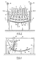
- Figure 5 shows a variant of the device.
- the laminated glazing to be assembled 34 consists of two sheets of glass 35, 36 and an interlayer 37.
- the presser assembly is made up as before of a set of pressure rollers 4, each mounted at the end of the rod 5 of a jack 6.
- the body 7 of each jack is mounted adjustable in height and in orientation, on a transverse bar 38, extending over the entire width of the device.
- Each of the ends of the crossbar 38 is fixed to a carriage 39 which moves to follow the curvatures of the support and of the glazing.
- a guide device 40 provided for example with rollers 41 which follow the curvature of two rails 42 of shape adapted to that of the glazing arranged on each side of the support 2.
- the device shown in FIG. 6 is used for assembling an asymmetrical glazing formed from a rigid element 43, generally made of glass, and a sheet of plastic material 44.
- the sheet is in the form of a primitive cut beforehand approximately in the format of the glazing to be manufactured.
- One end of the sheet is pinched in the support 2 in its upstream part outside the limits of the glazing.
- the other end is held over its entire width by a clamping system 45, which keeps it stretched away from the support.
- the tensioning device is not shown in FIG. 6.
- the plastic sheet 44 may have a rectangular format or, advantageously, a trapezoidal format.
- two elements 46, 47 in the shape of a rectangular trapezoid, cut out from a less expensive material of the same thickness or of thickness less than that of the sheet 44 can be fixed, by means of staples or adhesive tape, to the two ends of the sheet 44, in order to constitute, with the sheet 44, a rectangle of adequate size.
- Such a sheet can be easily handled. It is fixed on the one hand to the support 2 and on the other hand to the clamping system 45 by its ends 46, 47.
- FIG. 6 bis represents such a sheet.
- the pressing assembly 48 is mounted articulated at the end of an arm 49 of an industrial robot, not shown.
- the active part consists of a flexible roller 31 bent under the action of two series of rollers 50, 51 mounted at the end of rods 52 actuated by springs 53.
- Figures 7 and 8 show a variant of a device according to the invention which is equipped with a support 54 of shape adapted to the form of glazing to be assembled 55, which can tilt around a longitudinal axis 56 and around a transverse axis 57.
- the glazing to be assembled is an asymmetrical laminated glazing consisting of a rigid sheet generally made of glass 58 and a sheet of plastic material 59.
- the sheet 59 is in the form of a primitive cut beforehand approximately in the format of the glazing to be manufactured. It was previously enclosed in a cassette 60 in which it is kept taut, for example by means of rollers (not shown in the figure) arranged laterally over the entire length of the cassette.
- the cassette can possibly be equipped with cleaning means which combine the wiping, scraping and suction operations at the same time as the sheet is discharged from its static electricity.
- the cassette can contain one or more sheets 59 arranged in parallel and kept slightly apart from one another.
- the cassette is loaded on the presser assembly before the assembly operation. It is fixed, in a vertical position, to the front of the presser assembly, by an appropriate means, for example clipping, by resting on the uprights 13 and 14.
- the cassette 60 is removed when it is empty, to be reloaded with plastic film formats.
- the presser assembly 61 includes the same means as those shown in FIGS. 3 and 4, but in addition, it is equipped with a gripping system 62, extending over the entire width of the device, intended to hold and guide the sheet 59 at the front of the flexible roller 31.
- the sheet can slide without damage on this system.
- This gripping system can be obtained, for example, by a suction acting on the entire width of the sheet or by electrostatic plating.
- the support 54 is in equilibrium on a longitudinal axis 56 by means of bearings 64, 65, fixed on a plate 63, itself in equilibrium on a horizontal transverse axis 57.
- the axis 56 is located in the median vertical plane passing through the support 54 in the direction of movement.
- the support 54 can freely pivot around the axis 56 under the effect of the pressure exerted by the flexible roller 31 whatever the position of the latter along the glazing 55.
- a support device 72, 73 of variable height controlled as a function of the position of the presser assembly on the glazing to be assembled.
- This support device makes it possible to provide adequate back pressure in an appropriate manner, without opposing the displacement of the presser assembly.
- the support devices 72, 73 can be obtained, for example, by means of jacks or cams.
- Figures 7 and 8 show support devices produced by means of cams adapted to the glazing.
- the two cams 66, 67 located in the vertical, longitudinal, median plane of the support 54, rotate around the horizontal axes 68, 69 arranged at a fixed distance from the axis 57.
- the support 54 is supported on one or the other of the cams, as a function of the position of the presser assembly on the glazing, by means of the rollers 70, 71.
- the device works as follows:
- the presser assembly is in the starting position at the end A of the support 54.
- a film cassette 60 is fixed by clipping on the front of the presser assembly.
- Cam 67 is in the low position.
- the support is supported on the cam 67, via the roller 71, and on the axis 57. It is not supported on the cam 66.
- the support is then in the inclined position.
- the movement from end A to the middle position of the pressing assembly controls the rotation of the cams 66 and 67 so that they reach their high position when the presser assembly reaches the middle position.
- the support 54 comes into contact with the cam 66 via the roller 70 (fig. 7).
- the support is then horizontal.
- the movement continues towards the end B and causes the cams to rotate.
- the roller 71 leaves the cam 67.
- the support, more and more inclined, is then in abutment on the axis 57 and on the cam 66.
- FIG. 9 shows another variant of the device according to the invention, which is used for assembling an asymmetrical laminated glazing like the previous device.
- the support 54 of a shape adapted to the glazing to be assembled 55, can tilt around a longitudinal axis 56 and around two transverse axes 74 and 75 from which it can escape.
- two height-adjustable support systems controlled as a function of the position of the presser assembly on the glazing, press on the plate 76.
- These support systems are for example jacks or cams.
- FIG. 9 shows a system of jacks 77, 78.
- the device works as follows:
- the support is inclined. It is held by the cylinder 78, in the low position, by the transverse axis 75 and by the cylinder 77 in the high position. Between positions B and C, the support is horizontal. It is supported on the two transverse axes 75 and 74. The varins 77, 78 are stopped, in the intermediate position. Beyond position C, the displacement of the pressing assembly again causes the support to tilt, which is then supported on the transverse axis 74, on the jack 77 and on the jack 78.
Landscapes
- Engineering & Computer Science (AREA)
- Manufacturing & Machinery (AREA)
- Joining Of Glass To Other Materials (AREA)
- Laminated Bodies (AREA)
Abstract
Description
L'invention est relative à l'assemblage de feuilles de verre et/ou de matières plastiques pour former un vitrage feuilleté.The invention relates to the assembly of glass sheets and / or plastic materials to form laminated glazing.
L'assemblage des vitrages feuilletés s'effectue généralement par un pressage préliminaire des éléments constitutifs du vitrage feuilleté, par calandrage suivi d'un cycle d'autoclave qui améliore l'adhésion entre les éléments et assure un assemblage définitif.The assembly of the laminated glazings is generally carried out by a preliminary pressing of the constituent elements of the laminated glazing, by calendering followed by an autoclave cycle which improves the adhesion between the elements and ensures a final assembly.
Pour les vitrages feuilletés "traditionnels" dont les deux faces extérieures sont formées d'éléments rigides, par exemple deux feuilles de verre, on utilise généralement un dispositif comprenant deux séries superposées de galets disposés les uns à côtés des autres, leur position pouvant être réglée indépendemment les uns des autres, de façon à obtenir la courbure transversale désirée.For "traditional" laminated glazing, the two outer faces of which are formed of rigid elements, for example two sheets of glass, a device is generally used comprising two superimposed series of rollers arranged one next to the other, their position being adjustable. independently of each other, so as to obtain the desired transverse curvature.
Si ce dispositif s'applique parfaitement bien à la fabrication d'un vitrage feuilleté dont les deux faces extérieures sont rigides, il n'en est pas de même lorsqu'il s'agit d'assembler une feuille souple avec un support rigide pour former un vitrage asymétrique comme décrit par exemple dans les publications de brevets français 2 187 719, 2 398 606, et européens 0 132 198, 0 131 523. On observe alors de nombreuses bulles d'air dans le vitrage, dans les bandes correspondant aux espaces entre galets voisins de la série de galets qui agit sur la feuille souple.If this device applies perfectly well to the manufacture of laminated glazing whose two outer faces are rigid, it is not the same when it comes to assembling a flexible sheet with a rigid support to form asymmetrical glazing as described for example in French patent publications 2,187,719, 2,398,606, and European patent 0 132,198, 0 131,523. Many air bubbles are then observed in the glazing, in the bands corresponding to the spaces between neighboring rollers of the series of rollers which acts on the flexible sheet.
Pour assembler ce type de vitrage feuilleté dit asymétrique en évitant les bulles d'air, on a déjà proposé dans la publication de brevet européen 0 015 209 un dispositif comprenant : des moyens inférieurs de pinçage disposés suivant une courbure, sensiblement celle d'une courbure de la face inférieure du vitrage à assembler transversalement à sa direction de déplacement ; un rouleau presseur cylindrique, souple, disposé au-dessus des moyens inférieurs de pinçage, s'étendant sur une longueur au moins égale à la largeur des éléments à assembler, c'est-à-dire au moins égale à la dimension transversale des éléments à assembler par rapport à leur direction de déplacement ; des moyens supérieurs s'appuyant sur le rouleau presseur pour lui donner la courbure désirée, sensiblement celle d'une courbure de la face supérieure du vitrage à assembler transversalement à sa direction de déplacement, qui le maintiennent dans sa position de travail à une distance des moyens inférieurs, légèrement inférieure à l'épaisseur totale des éléments à assembler ou même nulle; des moyens assurant l'entraînement en rotation du rouleau presseur et/ou d'une partie ou de la totalité des moyens inférieurs de pinçage.To assemble this type of laminated glazing called asymmetrical glazing while avoiding air bubbles, a device has already been proposed in European patent publication 0 015 209 comprising: lower clamping means arranged along a curvature, substantially that of a curvature from the underside of the glazing to be assembled transversely to its direction of movement; a flexible cylindrical pressure roller, disposed above the lower clamping means, extending over a length at least equal to the width of the elements to be assembled, that is to say at least equal to the transverse dimension of the elements to be assembled relative to their direction of movement; superior means pressing on the pressure roller to give it the curvature desired, substantially that of a curvature of the upper face of the glazing to be assembled transversely to its direction of movement, which maintain it in its working position at a distance from the lower means, slightly less than the total thickness of the elements to be assembled or even zero; means ensuring the rotary drive of the pressure roller and / or part or all of the lower clamping means.
Ce dispositif donne entière satisfaction pour la plupart des vitrages, mais la feuille souple qui peut être assemblée avec le support rigide doit être présentée à l'assemblage sous la forme d'un ruban continu.This device gives complete satisfaction for most glazing, but the flexible sheet which can be assembled with the rigid support must be presented for assembly in the form of a continuous ribbon.
Un autre inconvénient est que ce dispositif est difficilement utilisable pour l'assemblage de vitrages fortement cintrés dans le sens de la longueur qui correspond au sens du déplacement.Another drawback is that this device is difficult to use for assembling strongly curved glazing in the direction of the length which corresponds to the direction of movement.
L'invention propose un dispositif qui obvie aux inconvénients cités et qui s'applique parfaitement bien à l'assemblage préliminaire ou définitif des vitrages feuilletés, qu'ils soient "traditionnels" ou "asymétriques", de formes complexes avec différents rayons de courbure fortement cintrés ou non, comme décrit précédemment.The invention proposes a device which overcomes the aforementioned drawbacks and which applies perfectly well to the preliminary or final assembly of laminated glazings, whether they are "traditional" or "asymmetrical", of complex shapes with different radii of curvature strongly curved or not, as described above.
Le dispositif selon l'invention, comprend un support, de forme adaptée à la géométrie du vitrage, assurant le maintien du vitrage, un ensemble supérieur presseur muni de moyens lui permettant de se déplacer dans les deux sens selon une direction du vitrage, cet ensemble presseur s'étendant au dessus du support, transversalement à la direction du déplacement, en épousant le profil transversal du vitrage, l'ensemble presseur, au moins, étant articulé afin que les efforts de pressage s'exercent sensiblement perpendiculairement à la surface du vitrage durant tout le pressage.The device according to the invention comprises a support, of shape adapted to the geometry of the glazing, ensuring the maintenance of the glazing, an upper presser assembly provided with means allowing it to move in both directions in a direction of the glazing, this assembly presser extending above the support, transverse to the direction of movement, following the transverse profile of the glazing, the presser assembly, at least, being articulated so that the pressing forces are exerted substantially perpendicular to the surface of the glazing during the whole pressing.
Selon une caractéristique avantageuse du dispositif, le support est monté pivotant, au moins autour d'un axe transversal par rapport à la direction du déplacement.According to an advantageous characteristic of the device, the support is pivotally mounted, at least about an axis transverse to the direction of movement.
Les pivotements des moyens supérieurs de pressage associés aux pivotements du support assurent le maintien des efforts de pressage dans une direction qui reste essentiellement perpendiculaire à la surface du vitrage durant tout le déplacement des moyens supérieurs de pressage pendant l'opération d'assemblage.The pivoting of the upper pressing means associated with the pivoting of the support ensures that the pressing forces are maintained in a direction which remains essentially perpendicular to the surface of the glazing throughout the movement of the upper pressing means during the assembly operation.
Selon une réalisation du dispositif, l'ensemble presseur est un ensemble de galets montés au bout de systèmes élastiques, tels des ressorts ou des vérins exerçant une force de pressage sur la face supé rieure du vitrage, et disposés selon une courbure sensiblement égale à la courbure du profil transversal du vitrage.According to one embodiment of the device, the presser assembly is a set of rollers mounted at the end of elastic systems, such as springs or jacks exerting a pressing force on the upper face. of the glazing, and arranged in a curvature substantially equal to the curvature of the transverse profile of the glazing.
Dans une variante, l'ensemble presseur est un rouleau cylindrique presseur souple, notamment formé d'au moins une couche de caoutchouc vulcanisé, et cintré par des moyens s'appuyant sur lui, pour lui donner toute courbure désirée, correspondant sensiblement au profil de la face supérieure du vitrage à assembler, transversalement à sa direction de déplacement et qui maintiennent le rouleau presseur dans sa position de travail au contact de la face supérieure du vitrage.Alternatively, the pressing assembly is a flexible cylindrical pressing roller, in particular formed from at least one layer of vulcanized rubber, and bent by means resting on it, to give it any desired curvature, corresponding substantially to the profile of the upper face of the glazing to be assembled, transverse to its direction of movement and which keep the pressure roller in its working position in contact with the upper face of the glazing.
Selon une caractéristique du dispositif l'ensemble supérieur presseur est monté au bout de moyens se déplaçant le long de rail disposé dans la direction du déplacement.According to a characteristic of the device, the upper presser assembly is mounted at the end of means moving along the rail disposed in the direction of movement.
Selon une autre caractéristique du dispositif, l'ensemble supérieur presseur est monté au bout de moyens assurant la mobilité en rotation afin d'exercer un effort perpendiculaire à la surface du vitrage au cours du déplacement de l'ensemble presseur. Les moyens assurant la mobilité en rotation et le déplacement de l'ensemble presseur est selon un aspect de l'invention le bras d'un robot industriel.According to another characteristic of the device, the upper presser assembly is mounted at the end of means ensuring rotational mobility in order to exert a force perpendicular to the surface of the glazing during the movement of the presser assembly. The means ensuring the rotational mobility and the displacement of the presser assembly is, according to one aspect of the invention, the arm of an industrial robot.
Selon une autre caractéristique du dispositif, le support est avantageusement monté pivotant autour de plusieurs axes perpendiculaires à la direction du déplacement de l'ensemble presseur, par exemple autour de deux axes dont il peut s'échapper.According to another characteristic of the device, the support is advantageously mounted to pivot around several axes perpendicular to the direction of movement of the presser assembly, for example around two axes from which it can escape.
Selon une réalisation du dispositif, le support est en outre monté pivotant autour d'un axe longitudinal.According to an embodiment of the device, the support is further mounted pivoting about a longitudinal axis.
L'ensemble des pivotements dont peut être muni le support selon l'invention permet d'envisager l'assemblage de vitrages de formes très complexes.All of the pivoting with which the support according to the invention can be provided makes it possible to envisage the assembly of glazing of very complex shapes.
Le support peut être un cadre soutenant une partie au moins de la périphérie du vitrage, en particulier les deux extrémités.The support can be a frame supporting at least part of the periphery of the glazing, in particular the two ends.
Dans une variante, le support est une forme pleine ou essentiellement pleine qui soutient le vitrage en tout point, sur toute sa surface ou sur la partie essentielle de sa surface. Cette forme peut être constituée d'un même matériau ou de plusieurs matériaux de duretés différentes, pour compenser notamment les différences entre les efforts de pressage d'un endroit à un autre.In a variant, the support is a solid or essentially full form which supports the glazing at any point, over its entire surface or over the essential part of its surface. This shape can be made of the same material or of several materials of different hardnesses, in particular to compensate for the differences between the pressing forces from one place to another.
Afin de facilité le centrage et d'améliorer le maintien du vitrage durant l'opération d'assemblage, la forme présente une empreinte sur laquelle se place le vitrage et qui n'en émerge donc que d'une partie de son épaisseur.In order to facilitate centering and to improve the maintenance of the glazing during the assembly operation, the shape has an imprint on which the glazing is placed and which therefore only emerges from part of its thickness.
La forme s'étend avantageusement d'au moins un côté du vitrage sur une longueur permettant le positionnement correct de l'ensemble presseur à un moment ou l'autre de l'opération d'assemblage. On peut ainsi aussi prévoir des moyens de maintien de la feuille à assembler.The shape advantageously extends from at least one side of the glazing over a length allowing the correct positioning of the presser assembly at one time or the other of the assembly operation. It is thus also possible to provide means for holding the sheet to be assembled.
Un autre avantage du dispositif selon l'invention est qu'il permet d'utiliser aussi bien une feuille de longueur indéfinie qu'une feuille découpée en primitif dans le cas de l'assemblage d'un vitrage asymétrique.Another advantage of the device according to the invention is that it makes it possible to use both a sheet of indefinite length and a sheet cut into a primitive in the case of the assembly of asymmetrical glazing.
D'autres avantages et caractéristiques du dispositif selon l'invention apparaitront dans la suite de la description d'exemples de réalisations faite en référence aux figures.
- La figure 1 est une représentation schématique en vue de face d'une réalisation du dispositif pour l'assemblage de vitrage feuilleté traditionnel dont les deux faces extérieures sont formées d'éléments rigides.
- La figure 2 est une vue de côté du dispositif de la figure 1.
- La figure 3 est une représentation schématique en vue de face d'une réalisation du dispositif pour l'assemblage d'un vitrage feuilleté asymétrique, constitué d'un support rigide et d'une feuille souple en matière plastique.
- La figure 4 est une vue de côté du dispositif de la figure 3.
- La figure 5 est une représentation schématique en vue de côté, d'une variante du dispositif de la figure 1.
- La figure 6 est une repésentations schématique en vue de côté, d'une variante du dispositif selon laquelle le moyen assurant la mobilité et le déplacement de l'ensemble presseur est le bras d'un robot industriel.
- La figure 7 est une représentation schématique d'une autre réalisation du dispositif utilisant un support articulé autour d'un axe longitudinal et d'un axe transversal.
- La figure 8 est une représentation en position de sortie d'assemblage du dispositif de la figure 7.
- La figure 9 est une représentation schématique d'une ature réalisation du dispositif utilisant un support articulé autour d'un axe longitudinal et de deux axes transversaux.
- Figure 1 is a schematic representation in front view of an embodiment of the device for the assembly of traditional laminated glazing whose two outer faces are formed of rigid elements.
- Figure 2 is a side view of the device of Figure 1.
- Figure 3 is a schematic representation in front view of an embodiment of the device for assembling an asymmetrical laminated glazing, consisting of a rigid support and a flexible plastic sheet.
- FIG. 4 is a side view of the device of FIG. 3.
- FIG. 5 is a schematic representation in side view of a variant of the device in FIG. 1.
- Figure 6 is a schematic representation in side view of a variant of the device according to which the means ensuring the mobility and movement of the presser assembly is the arm of an industrial robot.
- Figure 7 is a schematic representation of another embodiment of the device using a support articulated around a longitudinal axis and a transverse axis.
- FIG. 8 is a representation in the assembly output position of the device in FIG. 7.
- Figure 9 is a schematic representation of an ature embodiment of the device using a support articulated around a longitudinal axis and two transverse axes.
Sur les figures 1 et 2, le vitrage à assembler 1 repose sur un support plein 2, qui épouse la forme du vitrage. L'ensemble presseur supérieur 3 est constitué d'une série de galets presseurs 4, montés chacun au bout de la tige 5 d'un vérin 6. Le corps 7 de chaque vérin est monté réglable en hauteur et en orientation sur une barre transversale 8 s'étendant sur toute la largeur du dispositif. La barre transversale 8 est fixée au bout de deux montants 9, 10.In FIGS. 1 and 2, the glazing to be assembled 1 rests on a
L'ensemble presseur 3 peut pivoter librement autour d'axes horizontaux 11, 12, réglables en hauteur, situés au niveau du plan du vitrage 1. Les axes 11, 12 traversent respectivement les montants 9, 10 et des montants verticaux 13, 14. La rotation de l'ensemble presseur 3 autour des axes 11, 12 est limitée par des butées mécaniques 15, 16, 17, 18 fixées sur les montants 13, 14. L'ensemble est équilibré par des contrepoids non représentés, et avantageusement de manière à placer le centre de gravité de l'ensemble presseur sensiblement au niveau de la ligne de pressage.The
Les montants verticaux 13, 14 sont fixés au bout de deux coulisseaux 19, 20 qui sont montés coulissant le long de deux rails horizontaux 21, 22 s'étendant longitudinalement et supportés par des poutres 23, 24.The
Dans une version du dispositif, la position en hauteur des axes 11, 12 est commandée par des vérins.In one version of the device, the height position of the
Ce dispositif est utilisé pour assembler par exemple un vitrage feuilleté formé de deux feuilles 25, 26 de verre et d'un intercalaire 27. Il fonctionne de la manière suivante. On règle au préalable le niveau de chaque vérin par rapport à la barre transversale 8. On place le vitrage 1 sur le support 2. L'empreinte du vitrage est avantageusement marquée dans le support, ce qui facilite le placement correct du vitrage et permet le maintien du vitrage lors de l'assemblage. Par déplacement de l'ensemble presseur, on applique une force de pressage due à l'action des galets poussés par les vérins sur la face supérieure du vitrage. Le déplacement s'effectue d'un bord à l'autre du vitrage à partir d'une extrémité ou d'une position médiane.This device is used to assemble, for example, laminated glazing formed by two
Le support est avantageusement équipé d'éléments chauffants qui par conduction chauffe le vitrage afin d'améliorer l'adhésion des éléments entre-eux.The support is advantageously equipped with heating elements which by conduction heats the glazing in order to improve the adhesion of the elements to each other.
Sur les figures 3 et 4, le vitrage à assembler 28, est constitué d'un élément monolithique ou feuilleté rigide 29 et d'une feuille de matière plastique souple 30, par exemple la feuille décrite dans la publication du brevet européen 0 133 090, conférant au vitrage les propriétés désirées telles que des propriétés d'absorbeur d'énergie, des propriétés de surface, comme résistance à la rayure, à l'abrasion etc... Le dispositif pour l'assemblage comprend les mêmes moyens que précédemment, mais en outre, il est équipé d'un rouleau cylindrique presseur souple 31, d'un diamètre de l'ordre de 10 centimètres environ qui s'étend sur toute la largeur du dispositif et qui est cintré sous l'action d'une série de galets presseurs. Le rouleau presseur cylindrique est formé d'une ou plusieurs couches de caoutchouc vulcanisé. Deux rouleaux d'appui 32, 33 peuvent venir s'appliquer en amont et en aval sur le rouleau presseur et l'empêcher de s'échapper de l'action des galeurs presseurs supérieurs. La feuille de matière plastique 30 qui doit recouvrir l'élément rigide pour former le vitrage fait partie dans cet exemple de réalisation d'un ruban de longueur indéfinie. Elle est amenée par le dessus du dispositif tout en étant constamment maintenue tendue par un dispositif de tension non représenté.In FIGS. 3 and 4, the glazing to be assembled 28 consists of a rigid monolithic or
La figure 5 représente une variante du dispositif. Dans cet exemple, le vitrage feuilleté à assembler 34 est constitué de deux feuilles de verre 35, 36 et d'un intercalaire 37. L'ensemble presseur est constitué comme précédemment d'un ensemble de galets presseurs 4, montés chacun au bout de la tige 5 d'un vérin 6. Le corps 7 de chaque vérin est monté réglable en hauteur et en orientation, sur une barre transversale 38, s'étendant sur toute la largeur du dispositif. Chacun des bouts de la barre transversale 38 est fixé à un chariot 39 qui se déplace pour suivre les courbures du support et du vitrage. Sur le chariot de l'ensemble presseur est monté un dispositif de guidage 40 muni par exemple de roulettes 41 qui suivent la courbure de deux rails 42 de forme adaptée à celle du vitrage disposé de chaque côté du support 2.Figure 5 shows a variant of the device. In this example, the laminated glazing to be assembled 34 consists of two sheets of
Le dispositif représenté sur la figure 6 est utilisé pour l'assemblage d'un vitrage asymétrique formé d'un élément rigide 43, généralement en verre, et d'une feuille de matière plastique 44.The device shown in FIG. 6 is used for assembling an asymmetrical glazing formed from a
Dans ce dispositif, la feuille se présente sous la forme d'un primitif découpé au préalable approximativement au format du vitrage à fabriquer. Une extrémité de la feuille est pincée dans le support 2 dans sa partie amont en dehors des limites du vitrage. L'autre extrémité est tenue sur toute sa largeur par un système de pincement 45, qui la maintien tendue à distance du support. Le dispositif de tension n'est par représentée sur la figure 6.In this device, the sheet is in the form of a primitive cut beforehand approximately in the format of the glazing to be manufactured. One end of the sheet is pinched in the
La feuille de matière plastique 44 peut avoir un format rectangulaire ou, avantageusement, un format trapézoïdal. Dans ce cas, deux éléments 46, 47 en forme de trapèze rectangle, découpés dans une matière moins onéreuse de même épaisseur ou d'épaisseur inférieure à celle de la feuille 44, peuvent être fixés, au moyen d'agraffes ou de ruban adhésif, aux deux extrémités de la feuille 44, afin de constituer, avec la feuille 44, un rectangle de dimension adéquat. Une telle feuille peut être facilement manipulée. Elle est fixée d'une part au support 2 et d'autre part au système de pincement 45 par ses extrémités 46, 47. La figure 6 bis représente une telle feuille.The
Dans le dispositif représenté sur la figure 6, l'ensemble presseur 48 est monté articulé au bout d'un bras 49 d'un robot industriel non représenté. La partie agissante est constituée d'un rouleau souple 31 cintré sous l'action de deux séries de galets 50, 51 montés au bout de tiges 52 actionnées par des ressorts 53.In the device shown in FIG. 6, the pressing
Les figures 7 et 8 représentent une variante d'un dispositif selon l'invention qui est équipé d'un support 54 de forme adaptée à la forme de vitrage à assembler 55, pouvant basculer autour d'un axe longitudinal 56 et autour d'un axe transversal 57. Dans cet exemple le vitrage à assembler est un vitrage feuilleté asymétrique constitué d'une feuille rigide généralement en verre 58 et d'une feuille de matière plastique 59.Figures 7 and 8 show a variant of a device according to the invention which is equipped with a
Dans ce dispositif, la feuille 59 se présente sous la forme d'un primitif découpé au préalable approximativement au format du vitrage à fabriquer. Elle a été au préalable enfermée dans une cassette 60 dans laquelle est elle maintenue tendue par exemple à l'aide de molettes (non représentée sur la figure) disposées latéralement sur toute la longueur de la cassette.In this device, the
La cassette peut éventuellement être équipée de moyens de nettoyage qui combinent les opérations d'essuyage, de raclage, d'aspiration en même temps que l'on décharge la feuille de son électricité statique.The cassette can possibly be equipped with cleaning means which combine the wiping, scraping and suction operations at the same time as the sheet is discharged from its static electricity.
La cassette peut contenir une ou plusieurs feuilles 59 disposées parallèlement et maintenues légèrement distantes les unes des autres.The cassette can contain one or
La cassette est chargée sur l'ensemble presseur avant l'opération d'assemblage. Elle est fixée, en position verticale, sur le devant de l'ensemble presseur, par un moyen approprié, clipage par exemple, en prenant appui sur les montants 13 et 14. La cassette 60 est retirée lorsqu'elle est vide, pour être rechargée avec des formats de films en matière plastique.The cassette is loaded on the presser assembly before the assembly operation. It is fixed, in a vertical position, to the front of the presser assembly, by an appropriate means, for example clipping, by resting on the
L'ensemble presseur 61 comprend les mêmes moyens que ceux montrés sur les figures 3 et 4, mais en outre, il est équipé d'un système de préhension 62, s'étendant sur toute la largeur du dispositif, destinés à tenir et guider la feuille 59 à l'avant du rouleau souple 31. La feuille peut glisser sans dommage sur ce système. Ce système de préhension peut être obtenu, par exemple, au moyen d'une aspiration agissant sur toute la largeur de la feuille ou encore par placage électrostatique.The presser assembly 61 includes the same means as those shown in FIGS. 3 and 4, but in addition, it is equipped with a gripping
Le support 54 est en équilibre sur un axe longitudinal 56 au moyen de paliers 64, 65, fixés sur une platine 63, elle-même en équilibre sur un axe horizontal transversal 57.The
L'axe 56 est situé dans le plan vertical médian traversant le support 54 dans le sens du déplacement.The
Le support 54 peut librement pivoter autour de l'axe 56 sous l'effet de la pression exercée par le rouleau souple 31 quelque soit la position de ce dernier le long du vitrage 55.The
Au niveau de chacune des extrémités du support 54 est installé un dispositif de soutien 72, 73, à hauteur variable commandée en fonction de la position de l'ensemble presseur sur le vitrage à assembler. Ce dispositif de soutien permet d'assurer de façon convenable une contre-pression adéquate, sans s'opposer au déplacement de l'ensemble presseur. Les dispositifs de soutien 72, 73 peuvent être obtenus, par exemple, au moyen de vérins ou de cames.At each end of the
Les figures 7 et 8 montrent des dispositifs de soutien réalisés au moyen de cames de formes adaptées au vitrage. Les deux cames 66, 67 situés dans le plan vertical, longitudinal, médian du support 54, tournent autour des axes 68, 69 horizontaux disposés à distance fixe de l'axe 57. Le support 54 s'appuie sur l'une ou l'autre des cames, en fonction de la position de l'ensemble presseur sur le vitrage, au moyen des galets 70, 71.Figures 7 and 8 show support devices produced by means of cams adapted to the glazing. The two
Le dispositif fonctionne de la façon suivante :The device works as follows:
L'ensemble presseur est en position de départ à l'extrémité A du support 54. Une cassette de film 60 est fixée par clipage sur le devant de l'ensemble presseur. La came 67 est en position basse. Le support est en appui sur la came 67, par l'intermédiaire du galet 71, et sur l'axe 57. Il n'est pas en appui sur la came 66. Le support est alors en position inclinée.The presser assembly is in the starting position at the end A of the
Le déplacement depuis l'extrémité A jusqu'à la position médiane, de l'ensemble presseur commande la rotation des cames 66 et 67 de telle sorte qu'elles atteignent leur position haute au moment où l'ensemble presseur atteint la position médiane. Le support 54 vient au contact de la came 66 par l'intermédiaire du galet 70 (fig. 7). Le support est alors horizontal. Le déplacement se poursuit vers l'extrémité B et entraine une rotation des cames. Le galet 71 quitte la came 67. Le support, de plus en plus incliné, est alors en appui sur l'axe 57 et sur la came 66. Ainsi, qu'elle qu'ait été la position de l'ensemble presseur sur le vitrage, une contre-pression appropriée a toujours été assurée . De même, les efforts exercés par le rouleau souple 31 ont toujours agit sensiblement perpendiculairement au plan tangent.The movement from end A to the middle position of the pressing assembly controls the rotation of the
La figure 9 montre une autre variante du dispositif selon l'invention, qui est utilisée pour l'assemblage d'un vitrage feuilleté asymétrique comme le dispositif précédent.FIG. 9 shows another variant of the device according to the invention, which is used for assembling an asymmetrical laminated glazing like the previous device.
Le support 54, de forme adaptée au vitrage à assembler 55, peut basculer autour d'un axe longitudinal 56 et autour de deux axes transversaux 74 et 75 dont il peut s'échapper. Aux extrémités du support, deux systèmes de soutien à hauteur variable commandée en fonction de la position de l'ensemble presseur sur le vitrage, appuient sur la platine 76. Ces systèmes de soutien sont par exemples des vérins ou des cames. La figure 9 montre un système de vérins 77, 78.The
Le dispositif fonctionne de la façon suivante :The device works as follows:
Entre la position de départ A, et la position B, au droit de l'axe 75, le support est incliné. Il est tenu par le vérin 78, en position basse, par l'axe transversal 75 et par le vérin 77 en position haute. Entre les positions B et C, le support est horizontal. Il est en appui sur les deux axes transversaux 75 et 74. Les varins 77, 78 sont à l'arrêt, en position intermédiaire. Au delà de la position C, le déplacement de l'ensemble presseur entraine de nouveau le basculement du support qui est alors en appui sur l'axe transversal 74, sur le vérin 77 et sur le vérin 78.Between the starting position A and the position B, in line with the
Claims (16)
Applications Claiming Priority (2)
| Application Number | Priority Date | Filing Date | Title |
|---|---|---|---|
| FR8715624 | 1987-11-12 | ||
| FR8715624A FR2623126B1 (en) | 1987-11-12 | 1987-11-12 | DEVICE FOR ASSEMBLING SHEET WINDOWS |
Publications (1)
| Publication Number | Publication Date |
|---|---|
| EP0316224A1 true EP0316224A1 (en) | 1989-05-17 |
Family
ID=9356706
Family Applications (1)
| Application Number | Title | Priority Date | Filing Date |
|---|---|---|---|
| EP88402790A Withdrawn EP0316224A1 (en) | 1987-11-12 | 1988-11-07 | Apparatus for assembling laminated glass |
Country Status (5)
| Country | Link |
|---|---|
| EP (1) | EP0316224A1 (en) |
| JP (1) | JPH01160849A (en) |
| KR (1) | KR890007891A (en) |
| BR (1) | BR8805764A (en) |
| FR (1) | FR2623126B1 (en) |
Cited By (27)
| Publication number | Priority date | Publication date | Assignee | Title |
|---|---|---|---|---|
| US5154117A (en) * | 1990-01-16 | 1992-10-13 | Saint-Gobain Vitrage International | Device for the assembly of laminated glazing by pressing |
| WO2010055063A1 (en) * | 2008-11-12 | 2010-05-20 | Lm Glasfiber A/S | A method of laying a layer of fibre material and the related apparatus |
| WO2013163566A1 (en) * | 2012-04-26 | 2013-10-31 | Corning Incorporated | Glass sheet laminating system |
| US20160009025A1 (en) * | 2014-07-08 | 2016-01-14 | Samsung Display Co., Ltd. | Apparatus and method of manufacturing display apparatus |
| WO2018075853A1 (en) * | 2016-10-20 | 2018-04-26 | Corning Incorporated | Cold formed 3d cover glass articles and forming process to make the same |
| WO2018145721A1 (en) * | 2017-02-10 | 2018-08-16 | Asidium | Industrial machine for applying temporary or permanent protective films to planar surfaces acting simultaneously on two faces, having a system for cutting the film and positioning edge to edge or with a margin, automatically adapting to suit changes in the parts that are to be treated, using an electrostatic method |
| CN113001958A (en) * | 2021-02-26 | 2021-06-22 | 四川铭利达科技有限公司 | Full-automatic sticking film machine of plastic highlight product |
| FR3113664A1 (en) | 2020-08-27 | 2022-03-04 | Asidium | Device for an industrial flat lamination machine according to a principle of multiplication of lamination modules |
| US11292343B2 (en) | 2016-07-05 | 2022-04-05 | Corning Incorporated | Cold-formed glass article and assembly process thereof |
| US11332011B2 (en) | 2017-07-18 | 2022-05-17 | Corning Incorporated | Cold forming of complexly curved glass articles |
| US11331886B2 (en) | 2016-06-28 | 2022-05-17 | Corning Incorporated | Laminating thin strengthened glass to curved molded plastic surface for decorative and display cover application |
| US11384001B2 (en) | 2016-10-25 | 2022-07-12 | Corning Incorporated | Cold-form glass lamination to a display |
| US11459268B2 (en) | 2017-09-12 | 2022-10-04 | Corning Incorporated | Tactile elements for deadfronted glass and methods of making the same |
| US11518146B2 (en) | 2018-07-16 | 2022-12-06 | Corning Incorporated | Method of forming a vehicle interior system |
| US11550148B2 (en) | 2017-11-30 | 2023-01-10 | Corning Incorporated | Vacuum mold apparatus, systems, and methods for forming curved mirrors |
| US11586306B2 (en) | 2017-01-03 | 2023-02-21 | Corning Incorporated | Vehicle interior systems having a curved cover glass and display or touch panel and methods for forming the same |
| US11597672B2 (en) | 2016-03-09 | 2023-03-07 | Corning Incorporated | Cold forming of complexly curved glass articles |
| US11660963B2 (en) | 2017-09-13 | 2023-05-30 | Corning Incorporated | Curved vehicle displays |
| US11685685B2 (en) | 2019-07-31 | 2023-06-27 | Corning Incorporated | Method and system for cold-forming glass |
| US11685684B2 (en) | 2017-05-15 | 2023-06-27 | Corning Incorporated | Contoured glass articles and methods of making the same |
| US11718071B2 (en) | 2018-03-13 | 2023-08-08 | Corning Incorporated | Vehicle interior systems having a crack resistant curved cover glass and methods for forming the same |
| US11745588B2 (en) | 2017-10-10 | 2023-09-05 | Corning Incorporated | Vehicle interior systems having a curved cover glass with improved reliability and methods for forming the same |
| US11768369B2 (en) | 2017-11-21 | 2023-09-26 | Corning Incorporated | Aspheric mirror for head-up display system and methods for forming the same |
| US11767250B2 (en) | 2017-11-30 | 2023-09-26 | Corning Incorporated | Systems and methods for vacuum-forming aspheric mirrors |
| US11772491B2 (en) | 2017-09-13 | 2023-10-03 | Corning Incorporated | Light guide-based deadfront for display, related methods and vehicle interior systems |
| US11772361B2 (en) | 2020-04-02 | 2023-10-03 | Corning Incorporated | Curved glass constructions and methods for forming same |
| US11899865B2 (en) | 2017-01-03 | 2024-02-13 | Corning Incorporated | Vehicle interior systems having a curved cover glass and a display or touch panel and methods for forming the same |
Families Citing this family (2)
| Publication number | Priority date | Publication date | Assignee | Title |
|---|---|---|---|---|
| JP6491917B2 (en) * | 2015-03-24 | 2019-03-27 | 株式会社Screenラミナテック | Pasting device |
| JP6661587B2 (en) * | 2017-10-03 | 2020-03-11 | ショット グラス テクノロジーズ (スゾウ) カンパニー リミテッドSchott Glass Technologies (Suzhou) Co., Ltd. | Thin glass bonded article on a supporting substrate, method of making the same and use thereof |
Citations (3)
| Publication number | Priority date | Publication date | Assignee | Title |
|---|---|---|---|---|
| US2068104A (en) * | 1935-02-23 | 1937-01-19 | Duplate Corp | Apparatus for making curved safety glass |
| EP0015209A1 (en) * | 1979-02-21 | 1980-09-03 | Saint Gobain Vitrage International | Apparatus for assembling glass sheets and/or plastic sheets |
| US4679291A (en) * | 1986-02-26 | 1987-07-14 | Shell Oil Company | Robotic stapling system for fiber placement for composite parts |
-
1987
- 1987-11-12 FR FR8715624A patent/FR2623126B1/en not_active Expired - Fee Related
-
1988
- 1988-11-04 BR BR888805764A patent/BR8805764A/en unknown
- 1988-11-07 EP EP88402790A patent/EP0316224A1/en not_active Withdrawn
- 1988-11-09 KR KR1019880014684A patent/KR890007891A/en not_active Application Discontinuation
- 1988-11-11 JP JP63284030A patent/JPH01160849A/en active Pending
Patent Citations (3)
| Publication number | Priority date | Publication date | Assignee | Title |
|---|---|---|---|---|
| US2068104A (en) * | 1935-02-23 | 1937-01-19 | Duplate Corp | Apparatus for making curved safety glass |
| EP0015209A1 (en) * | 1979-02-21 | 1980-09-03 | Saint Gobain Vitrage International | Apparatus for assembling glass sheets and/or plastic sheets |
| US4679291A (en) * | 1986-02-26 | 1987-07-14 | Shell Oil Company | Robotic stapling system for fiber placement for composite parts |
Cited By (36)
| Publication number | Priority date | Publication date | Assignee | Title |
|---|---|---|---|---|
| US5154117A (en) * | 1990-01-16 | 1992-10-13 | Saint-Gobain Vitrage International | Device for the assembly of laminated glazing by pressing |
| WO2010055063A1 (en) * | 2008-11-12 | 2010-05-20 | Lm Glasfiber A/S | A method of laying a layer of fibre material and the related apparatus |
| CN102216056A (en) * | 2008-11-12 | 2011-10-12 | Lm玻璃纤维制品有限公司 | A method of laying a layer of fibre material and the related apparatus |
| WO2013163566A1 (en) * | 2012-04-26 | 2013-10-31 | Corning Incorporated | Glass sheet laminating system |
| US8916017B2 (en) | 2012-04-26 | 2014-12-23 | Corning Incorporated | Glass sheet laminating system |
| US20160009025A1 (en) * | 2014-07-08 | 2016-01-14 | Samsung Display Co., Ltd. | Apparatus and method of manufacturing display apparatus |
| US11597672B2 (en) | 2016-03-09 | 2023-03-07 | Corning Incorporated | Cold forming of complexly curved glass articles |
| US11331886B2 (en) | 2016-06-28 | 2022-05-17 | Corning Incorporated | Laminating thin strengthened glass to curved molded plastic surface for decorative and display cover application |
| US11338556B2 (en) | 2016-06-28 | 2022-05-24 | Corning Incorporated | Laminating thin strengthened glass to curved molded plastic surface for decorative and display cover application |
| US11292343B2 (en) | 2016-07-05 | 2022-04-05 | Corning Incorporated | Cold-formed glass article and assembly process thereof |
| US11850942B2 (en) | 2016-07-05 | 2023-12-26 | Corning Incorporated | Cold-formed glass article and assembly process thereof |
| US11607958B2 (en) | 2016-07-05 | 2023-03-21 | Corning Incorporated | Cold-formed glass article and assembly process thereof |
| US10953644B2 (en) | 2016-10-20 | 2021-03-23 | Corning Incorporated | Cold formed 3D cover glass articles and forming process to make the same |
| WO2018075853A1 (en) * | 2016-10-20 | 2018-04-26 | Corning Incorporated | Cold formed 3d cover glass articles and forming process to make the same |
| US11384001B2 (en) | 2016-10-25 | 2022-07-12 | Corning Incorporated | Cold-form glass lamination to a display |
| US11586306B2 (en) | 2017-01-03 | 2023-02-21 | Corning Incorporated | Vehicle interior systems having a curved cover glass and display or touch panel and methods for forming the same |
| US11899865B2 (en) | 2017-01-03 | 2024-02-13 | Corning Incorporated | Vehicle interior systems having a curved cover glass and a display or touch panel and methods for forming the same |
| US11065856B2 (en) | 2017-02-10 | 2021-07-20 | Asidium | Industrial machine for applying temporary or permanent protective films to planar surfaces acting simultaneously on two faces, having a system for cutting the film and positioning edge-to-edge or with a margin, automatically adapting to suit changes in the parts that are to be treated, using an electrostatic method |
| WO2018145721A1 (en) * | 2017-02-10 | 2018-08-16 | Asidium | Industrial machine for applying temporary or permanent protective films to planar surfaces acting simultaneously on two faces, having a system for cutting the film and positioning edge to edge or with a margin, automatically adapting to suit changes in the parts that are to be treated, using an electrostatic method |
| US11685684B2 (en) | 2017-05-15 | 2023-06-27 | Corning Incorporated | Contoured glass articles and methods of making the same |
| US11332011B2 (en) | 2017-07-18 | 2022-05-17 | Corning Incorporated | Cold forming of complexly curved glass articles |
| US11459268B2 (en) | 2017-09-12 | 2022-10-04 | Corning Incorporated | Tactile elements for deadfronted glass and methods of making the same |
| US11713276B2 (en) | 2017-09-12 | 2023-08-01 | Corning Incorporated | Tactile elements for deadfronted glass and methods of making the same |
| US11660963B2 (en) | 2017-09-13 | 2023-05-30 | Corning Incorporated | Curved vehicle displays |
| US11772491B2 (en) | 2017-09-13 | 2023-10-03 | Corning Incorporated | Light guide-based deadfront for display, related methods and vehicle interior systems |
| US11919396B2 (en) | 2017-09-13 | 2024-03-05 | Corning Incorporated | Curved vehicle displays |
| US11745588B2 (en) | 2017-10-10 | 2023-09-05 | Corning Incorporated | Vehicle interior systems having a curved cover glass with improved reliability and methods for forming the same |
| US11768369B2 (en) | 2017-11-21 | 2023-09-26 | Corning Incorporated | Aspheric mirror for head-up display system and methods for forming the same |
| US11550148B2 (en) | 2017-11-30 | 2023-01-10 | Corning Incorporated | Vacuum mold apparatus, systems, and methods for forming curved mirrors |
| US11767250B2 (en) | 2017-11-30 | 2023-09-26 | Corning Incorporated | Systems and methods for vacuum-forming aspheric mirrors |
| US11718071B2 (en) | 2018-03-13 | 2023-08-08 | Corning Incorporated | Vehicle interior systems having a crack resistant curved cover glass and methods for forming the same |
| US11518146B2 (en) | 2018-07-16 | 2022-12-06 | Corning Incorporated | Method of forming a vehicle interior system |
| US11685685B2 (en) | 2019-07-31 | 2023-06-27 | Corning Incorporated | Method and system for cold-forming glass |
| US11772361B2 (en) | 2020-04-02 | 2023-10-03 | Corning Incorporated | Curved glass constructions and methods for forming same |
| FR3113664A1 (en) | 2020-08-27 | 2022-03-04 | Asidium | Device for an industrial flat lamination machine according to a principle of multiplication of lamination modules |
| CN113001958A (en) * | 2021-02-26 | 2021-06-22 | 四川铭利达科技有限公司 | Full-automatic sticking film machine of plastic highlight product |
Also Published As
| Publication number | Publication date |
|---|---|
| FR2623126B1 (en) | 1990-02-16 |
| FR2623126A1 (en) | 1989-05-19 |
| BR8805764A (en) | 1989-07-25 |
| JPH01160849A (en) | 1989-06-23 |
| KR890007891A (en) | 1989-07-06 |
Similar Documents
| Publication | Publication Date | Title |
|---|---|---|
| EP0316224A1 (en) | Apparatus for assembling laminated glass | |
| EP0015209B1 (en) | Apparatus for assembling glass sheets and/or plastic sheets | |
| EP0438328B1 (en) | Apparatus for assembling by pressing laminated glass | |
| FR2631878A1 (en) | DEVICE FOR CUTTING A LAMINATE | |
| FR2581377A1 (en) | METHOD AND DEVICE FOR LOADING A PRINT SEPARATION SYSTEM, IN PARTICULAR FROM A FEEDER | |
| FR2683515A1 (en) | Apparatus for gripping and transporting stacks of flat objects | |
| EP0006385A1 (en) | Improvements in or relating to apparatuses with flexible pallets for the recovery of floating matter | |
| CA1328397C (en) | Method and device for coating a glass sheet with a flexible film | |
| FR2484974A1 (en) | APPARATUS FOR ALIGNING SHEETS | |
| FR2656252A1 (en) | APPARATUS AND METHOD FOR PRESSING OVERHEAD SHEETS TO FORM A FOIL PRODUCT SUCH AS A WINDSHIELD. | |
| FR2674787A1 (en) | COMBINED CUTTING MACHINE AND RECEPTION TABLE. | |
| FR2594651A1 (en) | MACHINE FOR FASTENING ON A CONTINUOUSLY FLOORING PATCH OF THE ELASTIC BAND TENSIONED STRINGS AND INSTALLATION FOR THE PRODUCTION OF CULOT LAYERS COMPRISING THE APPLICATION | |
| CH618940A5 (en) | ||
| FR2617122A1 (en) | Device for packaging a cylindrical product in a sheet | |
| EP0041899A1 (en) | Elements for bending plates in plastic condition, use of these elements in bending and tempering these plates and apparatus provided with these elements | |
| FR2626264A3 (en) | APPARATUS FOR DISPENSING AND WINDING FLOOR COVERINGS | |
| FR2620073A1 (en) | MACHINE FOR CUTTING WORKPIECES IN A BAND OF MATERIAL AND FOR JOINING WORKPIECES THAT HAVE BEEN CUTTING | |
| FR2646627A1 (en) | TREE TRUNK UNWINDER WITH IMPROVED ANTIFLEXION DEVICE | |
| FR2480720A1 (en) | Cardboard sheet stacking mechanism - has sloping feed conveyor under roller and has sprung guide plate over stack | |
| LU83240A1 (en) | WELDING MACHINE FOR WOUND THERMOPLASTIC SHEETS | |
| EP0301983A1 (en) | Apparatus for applying the ribbon that forms the sealing joint between the panes of a rectangular or square double glazing | |
| FR2668995A1 (en) | RETURN SYSTEM FOR CARRIER TRUCKS LINKED TO RAILS AND WITHOUT A CLEAN MOTOR SYSTEM. | |
| EP0351288B1 (en) | Apparatus for assembling laminated glass | |
| FR2614834A1 (en) | METHOD AND DEVICE FOR CALIBRATING LAMINATED GLAZING | |
| BE823679A (en) | PLASTIC BAG FORMING MACHINE |
Legal Events
| Date | Code | Title | Description |
|---|---|---|---|
| PUAI | Public reference made under article 153(3) epc to a published international application that has entered the european phase |
Free format text: ORIGINAL CODE: 0009012 |
|
| AK | Designated contracting states |
Kind code of ref document: A1 Designated state(s): AT BE CH DE ES FR GB IT LI LU NL SE |
|
| 17P | Request for examination filed |
Effective date: 19891110 |
|
| RAP3 | Party data changed (applicant data changed or rights of an application transferred) |
Owner name: SAINT GOBAIN VITRAGE INTERNATIONAL |
|
| 17Q | First examination report despatched |
Effective date: 19910709 |
|
| STAA | Information on the status of an ep patent application or granted ep patent |
Free format text: STATUS: THE APPLICATION HAS BEEN WITHDRAWN |
|
| 18W | Application withdrawn |
Withdrawal date: 19911125 |