EP0310728B1 - Device for extending the resolution of a n-bit resistive digital to analog converter to a (n+p)-bit digital to analog - Google Patents
Device for extending the resolution of a n-bit resistive digital to analog converter to a (n+p)-bit digital to analog Download PDFInfo
- Publication number
- EP0310728B1 EP0310728B1 EP87480013A EP87480013A EP0310728B1 EP 0310728 B1 EP0310728 B1 EP 0310728B1 EP 87480013 A EP87480013 A EP 87480013A EP 87480013 A EP87480013 A EP 87480013A EP 0310728 B1 EP0310728 B1 EP 0310728B1
- Authority
- EP
- European Patent Office
- Prior art keywords
- switches
- bits
- string
- bit
- analog converter
- Prior art date
- Legal status (The legal status is an assumption and is not a legal conclusion. Google has not performed a legal analysis and makes no representation as to the accuracy of the status listed.)
- Expired - Lifetime
Links
Images


Classifications
-
- H—ELECTRICITY
- H03—ELECTRONIC CIRCUITRY
- H03M—CODING; DECODING; CODE CONVERSION IN GENERAL
- H03M1/00—Analogue/digital conversion; Digital/analogue conversion
- H03M1/66—Digital/analogue converters
- H03M1/661—Improving the reconstruction of the analogue output signal beyond the resolution of the digital input signal, e.g. by interpolation, by curve-fitting, by smoothing
-
- H—ELECTRICITY
- H03—ELECTRONIC CIRCUITRY
- H03M—CODING; DECODING; CODE CONVERSION IN GENERAL
- H03M1/00—Analogue/digital conversion; Digital/analogue conversion
- H03M1/66—Digital/analogue converters
- H03M1/68—Digital/analogue converters with conversions of different sensitivity, i.e. one conversion relating to the more significant digital bits and another conversion to the less significant bits
- H03M1/682—Digital/analogue converters with conversions of different sensitivity, i.e. one conversion relating to the more significant digital bits and another conversion to the less significant bits both converters being of the unary decoded type
-
- H—ELECTRICITY
- H03—ELECTRONIC CIRCUITRY
- H03M—CODING; DECODING; CODE CONVERSION IN GENERAL
- H03M1/00—Analogue/digital conversion; Digital/analogue conversion
- H03M1/66—Digital/analogue converters
- H03M1/74—Simultaneous conversion
- H03M1/76—Simultaneous conversion using switching tree
- H03M1/765—Simultaneous conversion using switching tree using a single level of switches which are controlled by unary decoded digital signals
Definitions
- This invention relates to a device intended to be incorporated into a N-bit digital to analog converter DAC having a (N + P)-bit accuracy, to extend its resolution to a (N + P)-bit digital to analog converter.
- Digital to analog converters DAC are components widely used in data processing systems.
- resistive N-bit digital to analog converters are built from a thin film resistor string with 2 N taps.
- One N-bit DAC stage is cascaded with another P-bit DAC stage, such as described in US patent 4,543,560 through buffer amplifiers, to extend the conversion capabilities of the N-Bit DAC to (N + P)-bits.
- the buffer amplifiers are space consuming, when the DAC converter is integrated in a chip.
- E.P.-A-0123222 describes a N-bit digital to analog converterwhich can be extended to a (N + 1 )-bit (and possibly N + 2) DAC. It comprises several combined switching and resistive devices connectable to several consecutive taps of the resistor string, six taps for extension of two bits as shown in Figure 6.
- the dividers are made with a diffusion resistor chain (coarse divider) and a polysilicon string (fine divider). As a consequence, integrating this converter into a chip with switches having an ON resistance equal to RB/2 will be difficult.
- An object of the present invention is to design a (N + P)-bit resistive digital to analog converter from a N-BIT DAC without any accuracy degradation.
- Another object of the present invention is to design such a digital to analog converter, which minimizes the conversion time added by the P-bit extension.
- Another object of the present invention is to design such a (N + P)-bit digital to analog converter which keeps the intrinsic monotonicity of the N-bit digital to analog converter.
- Another object of the present invention is to design such (N + P)-bit digital to analog converter which minimizes the area of the DAC lay-out when integrated in a chip.
- the device allows the resolution of an N-bit digital to analog converter having N-digital inputs (A6..A3) and one output (7) to be extended to an (N + P)-bit digital to analog converter having (N + P) digital inputs (A6..A0) set to a first or second binary value (0 or 1) and one output, for converting an (N + P)-bit into an analog voltage generated on the output of the (N + P)-bit digital to analog converter.
- the N-bit digital to analog converter comprises a first string (2) made of 2 N resistive elements (R1 to R16), each having a first and a second tap, said string being mounted in series between a first terminal connected to a first voltage (VI) and a second terminal connected to a second voltage (V2), and a first set of at least 2 N switches (10,12), each switch being mounted between the first tap of a resistive element and the N-bit digital to analog converter output and being responsive to a combination of the values of the N digital inputs to establish a first conductive path between the first tap of a selected one of said resistive elements and the output of the N-bit digital to analog converter.
- the switches in the second set when closed present the same impedance as the switches in the first set, whereby the first and second conductive paths present the same impedance (Z).
- the active devices of the second string present when closed the same impedance as the switches in the first and second sets which comprise the first and second conductive paths, whereby said first and second paths are part of said second string.
- the first set of switches comprises:
- Figure 1 shows the resistor and switch arrangement of a conventional N-bit digital to analog converter.
- N has been chosen equal to 4.
- Figure 2 shows how this arrangement, may be extended to built a 4 + P digital to analog converter, when P is equal to 3.
- the 4-bit input word which is provided to the arrangement of figure 1, comprises four bits A6, A5, A4, A3.
- switches comprise the MSB switch block 4.
- the switches are arranged into four groups comprising four switches.
- the first group comprises switches SW1 to SW4, second group comprises switches SW5 to SW 8, third group comprises switches SW9 to SW12 and fourth group comprises switches SW13 to SW16.
- the first terminal of each switch is connected to a corresponding tap of the resistor string.
- the second terminals of first, second, third and fourth switches in the four groups are connected in common to output nodes OUT1, OUT2, OUT3 and OUT4 respectively.
- Output nodes OUT1 to OUT4 are connected to LSB switch block 6, comprising switches SW17, SW18, SW19 and SW20.
- the first terminals of switches SW17 to SW20 are connected to nodes OUT1 to OUT4 respectively.
- the close or open status of the switches of the first switching arrangement depends upon the value of the most significant bits MSB: A6 and A5 and the status of switches in the second switching arrangement depends upon the value of the least significant bits LSB: A4 and A3.
- switches SW1 to SW4 in the first group are closed when A6 and A5 are 00
- switches SW5 to SW8 in the second group are closed when A6 and A5 are 01
- switches SW9 to SW12 in the third group are closed when A6 and A5 are 10
- SW13 to SW16 are closed when A6 and A5 are 11.
- SW17 is closed when A4 are 00.
- SW18 is closed when A4 and A3 are 01.
- SW19 is closed when A4 and A3 are 10.
- SW20 is closed when A4 and A3 are 11.
- switches are controlled by the output of MSB and LSB decoders which are not shown in the figure 1.
- Figure 1 shows the status of the switches in case A4, A5, A4 and A3 are 0101 respectively, so that the voltage V6 at node N6 is provided at the analog output OUT.
- the switches in each 2 m groups will be controlled by one of the 2 m combinations of m MSB bits and the switches in block 6 will be controlled by the 2 combinations of the I bits.
- block 6 is not needed and block 10 comprises 2 n switches.
- a 4-bit resistive digital to analog converter as shown in figure 1 may be extended to a (4 + P)-bit digital to analog converter, by providing an additional string, comprising 2 P elements provided with taps and arranged to divide the voltage difference across a selected one of the resistors R1 to 16 by 2 P .
- Figure 2 shows the implementation of this concept when P is equal to 3.
- the device comprises the resistive string 2, MSB switch block 10, three LSB switch blocks 12, 14 and 16 and string 18.
- Resistive string 2 comprises addition taps, namely taps N4-2, N8-2, N12-2, duplicating taps N5, N9, 13 and tap N16-2 located at the upper terminal of resistor R16 connected to voltage V2.
- Additional switches SW4-1, SW8-2, SW12-2 and SW16-2, which are part of the first, second, third and fourth groups of switches are connected to these additional taps, on one side and to an additional common point OUT5 on the other side. They are controlled by the same logical conditions as the switches in the first, second, third and fourth groups, respectively.
- Nodes OUT1, OUT2, OUT3 and OUT4 are connected to the switches in the LSB SWITCH DOWN block 12 which comprises switches SW17-1, SW18-1, SW19-1, SW20-1 which are arranged and controlled as the corresponding switches in block 6 of figure 1.
- Nodes OUT2, OUT3, OUT4 and OUT5 are connected to LSB SWITCH UP block 14 which comprises switches SW17-2, SW18-2, SW19-2 and SW20-2, which are arranged as corresponding switches SW17-1 to SW20-1 in block 12 with respect to nodes OUT2 to OUT5 and controlled by the same logical conditions.
- the common points M1 and M7 of switches Sw17-1 to SW20-1 and SW17-2 to SW20-2 are connected to the ends of string 18.
- This string contains 2 P- 2 resistive elements Z1 to Z6 for the reasons which will be explained later.
- Taps M2, M3, M4, M5 and M6 are provided at the common points of two consecutive elements of the string.
- LSB output switch block 16 comprising switches SW22, SW23, SW24, SW25, SW26, SW27 and SW28 is controlled by the P additional bits A2, A1 and A0.
- the first terminals of these switches SW22 to SW28 are connected to taps M1 to M7 respectively and the second terminals are connected to common node 20.
- Node 20 is connected to the input of output amplifier 8 in the same way as node 7 of figure 1. The logical conditions which cause these switches to be closed are indicated in figure 2.
- a string disconnection means which is schematically represented in figure 2 by switch SW21, is provided to disconnect the string 18 from the taps M1 and M7, when the least significant bits A2, A1 and AO are 000, or when the converter is used as a N-bit digital to analog converter. This is performed by means of OR circuit 22, the inputs of which are active, when the three bits A2, A1 and AO are at 0 or when a programming input PI is at 1. This is schematically represented in figure 2.
- the MSB switches in block 10 have the same impedance and the LSB switches in block 12 and 14 also have the same impedance.
- One MSB switch associated to one LSB switch present a finite memori resistance Z in the range of 10 kiloohms which is high with respect to the unit resistor value R, which is in the range of 5 ohms.
- the impedance of the elements Z1 to Z6 is referenced by Z.
- switches SW-5 to SW8 and SW8-2 in the second group of switches in block 10 are closed, the other switches in this block are open, as shown in figure 2.
- Switches SW18-1 and SW18-2 in blocks 12 and 14 are closed.
- Switch SW 22 is closed and since switch SW21 is open the voltage at node N6 is provided to output node 20.
- the string 18 is connected between M1 and M7.
- node N6 is connected to node N7 through a bridge comprising, one resistive element, the impedance of which is equivalent to the resistance of closed switches SW6 and SW18-1, i.e. Z, the six elements of string 18 and one element the impedance of which is equivalent to the resistance of closed switches SW7 and SW18-2, i.e. Z.
- the voltages at taps M1 to M7 are the following, assuming Vx is the voltage at a tap Nx selected by the N-most significant bits of the (N + P)-bit word, i.e. top N6 as shown in figure 2.
- One of this voltage is provided to node 20, by means of one among switches SW22 to SW28 in block 16, which is closed depending upon the value of the P bits, as shown in figure 2. For example, if the P bits were 001, switch SW22 will be closed. If they were 111, switch SW28 will be closed.
- Switch 22 is also closed, when the P bits are 000, in which case, switch SW21 is open.
- N4-2, N8-2 are provided at nodes N5, N9, N13 and an additional tap N16-2 is provided at the uppermost terminal of resistor R16, to allow the string 18 to be connected across resistors R4, R8, R12 and R16.
- FIG. 3 represents a detailed implementation of the switches and elements Z1 to Z6.
- Switches SW18-1 and SW18-2 have the same structure.
- Switch SW18-1 comprises NMOS transistor TN18-1 and PMOS transistor TP18-1 and switch SW18-2 comprises NMOS transistor TN18-2 and PMOS transistor TP18-2.
- These complementary transistors are parallely mounted and are serially mounted with MSB switch transistors T6, T7, as shown in figure 3.
- NMOS and PMOS transistors switch SW18 are made ON when the logical condition A4.A3 is met.
- the corresponding output line 34 of bit decoder 36 is provided to the gates of transistors TN18-2 and TN18-1. This line is also provided to inverters 118-1 and 118-2, the outputs of which are provided to the gates of PMOS transistors TP18-1 and TP18-2.
- Elements Z1 to Z6 comprise NMOS transistor TNM and PMOS transistor TPM which are parallely mounted and the gate of which is connected to output line 38 of decoder 30 activated when A6 is equal to 0.
- TNM transistors of resistive elements Z1 to Z6 are ON to copy the impedance of the NMOS making up switches SW1 to SW8, SW4-2 and SW8-2.
- TPM transistors of resistive elements Z1 to Z6 are ON to copy the impedance of the PMOS transistors making up switched SW9 to SW16, SW12-2 and SW16-2.
- Transistors TNM and TPM in elements Z1 to Z6 must track NMOS and PMOS transistors making up block 10.
- Elements Z1 to Z6 also comprise NMOS transistor TNL and PMOS transistor TPL which are parallely mounted and arranged in series with transistors TNM and TPM.
- Transistors TNL ad TPL are arranged as transistors TN18 and TP18 making up switches SW18-1 and SW18-2.
- the gate of transistors TNL in elements Z1 to Z6 are connected to output line 40 of decoder 42 through OR gate 22 line 40 is at zero level when A2, A1 and AO are at 0, to causes transistors TNL of elements Z1 to Z6 to be off, to disconnect the string 18 from nodes M1 and M7.
- Output line 41 of OR circuit 22 is provided to inverters INV in elements Z1 to Z6, the output lines of which are provided to the gates of transistors TPL to cause these transistors to be OFF when line 40 is at 0 level.
- NMOS transistors TNL must track NMOS transistors of LSB switch UP and DOWN blocks 12 and 14.
- PMOS transistors TPL must track PMOS transistors of blocks 12 and 14.
- Output switches SW22 to SW28 have the same structures as switches SW 18-1 and 18-2, their gates are controlled by the output signals on lines 44 to 50 of decoder 42 which are active when the logical conditions indicated in figures 2 and 3 are met.
- the resolution may be extended by 1, by dividing the voltage across a selected resistor in string 2 by 2. This may be done by connecting nodes M1 and M4 to output 20, through output switches SW22 and SW25 controlled by the value 0 or 1 of the additional bit.
- switches SW1-1 to SW16-1 having the same impedance, when closed, as switches SW1 to SW16 in block 10 and controlled by the same logical conditions as switches SW1 to SW16.
- Switches SW1-1 to SW16-1 have first terminals connected in common to node M7 and second terminals connected to taps N1-2 to N15-2 duplicating taps N2, to N16 of the resistor string 2 and the tap N16-2, respectively.
- the resistive elements Z1 to Z6 only comprise NMOS and PMOS transistors TNM and TPM copying the NMOS or PMOS transistors in block 10.
- N 8
- P 4
Landscapes
- Engineering & Computer Science (AREA)
- Theoretical Computer Science (AREA)
- Analogue/Digital Conversion (AREA)
Description
- This invention relates to a device intended to be incorporated into a N-bit digital to analog converter DAC having a (N + P)-bit accuracy, to extend its resolution to a (N + P)-bit digital to analog converter.
- Digital to analog converters DAC are components widely used in data processing systems.
- There exist various types of digital to analog converters DAC, namely weighted current source DAC and resistive DAC.
- Presently, resistive N-bit digital to analog converters are built from a thin film resistor string with 2N taps.One N-bit DAC stage is cascaded with another P-bit DAC stage, such as described in US patent 4,543,560 through buffer amplifiers, to extend the conversion capabilities of the N-Bit DAC to (N + P)-bits.
- The presence of the buffer amplifiers between the two stages impairs the monotonicity of the conversion and increases the conversion time.
- Furthermore, the buffer amplifiers are space consuming, when the DAC converter is integrated in a chip.
- E.P.-A-0123222 describes a N-bit digital to analog converterwhich can be extended to a (N + 1 )-bit (and possibly N + 2) DAC. It comprises several combined switching and resistive devices connectable to several consecutive taps of the resistor string, six taps for extension of two bits as shown in Figure 6.
- Extension to a high number of bits is limited by the risk of non monotonic operations since several main ladder nodes are combined. In addition five switches may switch ON and OFF depending upon the input bits, this causes large perturbations of the analog voltages.
- IEEE JOURNAL OF SOLID STATE CIRCUITS, volume SC-18 n°3 June 1983, pages 297-301, describes a N-bit digital to analog converter according to the preamble of
claim 1 comprising two cascaded resistor strings, one string oparates as a coarse divider and the other one operates as a fine divider. Assuming N = n1 + n2, the coarse divider is made with 2n' RA resistors an the fine divider is made with 2n2-1 RB resistors because the switches can be designed with an ON resistance of 1/2 LSB fine resistor equivalent. - The dividers are made with a diffusion resistor chain (coarse divider) and a polysilicon string (fine divider). As a consequence, integrating this converter into a chip with switches having an ON resistance equal to RB/2 will be difficult.
- An object of the present invention is to design a (N + P)-bit resistive digital to analog converter from a N-BIT DAC without any accuracy degradation.
- Another object of the present invention is to design such a digital to analog converter, which minimizes the conversion time added by the P-bit extension.
- Another object of the present invention is to design such a (N + P)-bit digital to analog converter which keeps the intrinsic monotonicity of the N-bit digital to analog converter.
- Another object of the present invention is to design such (N + P)-bit digital to analog converter which minimizes the area of the DAC lay-out when integrated in a chip.
- The device according to the present invention allows the resolution of an N-bit digital to analog converter having N-digital inputs (A6..A3) and one output (7) to be extended to an (N + P)-bit digital to analog converter having (N + P) digital inputs (A6..A0) set to a first or second binary value (0 or 1) and one output, for converting an (N + P)-bit into an analog voltage generated on the output of the (N + P)-bit digital to analog converter. The N-bit digital to analog converter comprises a first string (2) made of 2N resistive elements (R1 to R16), each having a first and a second tap, said string being mounted in series between a first terminal connected to a first voltage (VI) and a second terminal connected to a second voltage (V2), and a first set of at least 2N switches (10,12), each switch being mounted between the first tap of a resistive element and the N-bit digital to analog converter output and being responsive to a combination of the values of the N digital inputs to establish a first conductive path between the first tap of a selected one of said resistive elements and the output of the N-bit digital to analog converter.
- The device also includes a second string of resistive elements and is characterized in that :
- - the second string (18) comprises 2P-2 active devices (Z1 to Z6), set in a closed status, selectively connectable in series between a first node (M1) connected to the N-bit digital to analog converter output, and a second node (M7), said elements having first and second pads, and in that it comprises :
- - a second set of switches (10,14;60), each switch being mounted between the second tap of a resistive element and the second node (M7), and being responsive to the same combinations of the N digital inputs as the first set of switches to establish a second conductive path between said second node (M7) and the second tap of the selected one of said resistive elements (R1 to R16), and
- - means (22, SW21) responsive to a specific combination of the P-bits to disconnect the second string from at least the first node (M1) and provide the voltage generated at the N-bit digital to analog converter output to the output of the(N + P)-bit digital to analog converter when said P-bits are set to the first value.
- The switches in the second set, when closed present the same impedance as the switches in the first set, whereby the first and second conductive paths present the same impedance (Z).
- The active devices of the second string present when closed the same impedance as the switches in the first and second sets which comprise the first and second conductive paths, whereby said first and second paths are part of said second string.
- In a preferred embodiment of the present invention, the first set of switches comprises:
- 2N MSB switches which are partitioned into 2m groups of 2t switches, where N is equal to m + and m is the number of most significant MSB bits (A6, A5) of the digital inputs and ℓ is the number of least significant bits (A4,A3) of the digital inputs, with 1<î<n, the 2t switches of each group being responsive to one of the 2m combinations of the m bits, each MSB switches having a first terminal connected to a first tap (N1 to N16) of the first resistive string, and a second terminal, the second terminals of the first, second, ..2tth switches of each group being connected to 2t common points (OUT1..0UT4)
- 2t first LSB switches (12) each one being responsive to one of the 2t combinations of the ℓ bits, and having a first terminal connected to one of the 2t common points and a second terminal connected to the first node (M1),
and the second set of switches comprises: - an additional switch in each group responsive to the same logical combinations of the m bits as the MSB switches comprising the group, and having a first terminal connected to the second tap of every 2ℓth resistive element and a second terminal connected to a (2t + 1)th common point,
- 2t second LSB switches, each one being responsive to the same combinations of the ℓ bits as the 2t first LSB switches and having a first terminal connected to one of the second to (2ℓ-1)th common points and a second terminal connected to the second node (M7), whereby for any combination of the N-bits, the first conductive path comprises a selected one of the 2N MSB switches in series with a selected one of the first LSB switches and the second conductive path comprises a selected one of the 2N MSB switches or one of the additional MSB switches in series with a selected one of the second LSB switches.
-
- Figure 1 shows a conventional 4-bit Digital to Analog Converter DAC.
- Figure 2 shows the device according to the present invention implemented in the DAC shown in Figure 1, to extend the conversion capability from 4-bits to 7-bits.
- Figure 3 shows the detailed implementation of the switching arrangements in
blocks - Figure 4 shows how the device according to the present invention is implemented when the N-bit DAC does not comprise
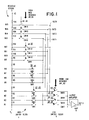
LSB block 12. - Figure 1 shows the resistor and switch arrangement of a conventional N-bit digital to analog converter. For the sake of clarity, N has been chosen equal to 4. Figure 2 shows how this arrangement, may be extended to built a 4 + P digital to analog converter, when P is equal to 3.
- The 4-bit input word which is provided to the arrangement of figure 1, comprises four bits A6, A5, A4, A3.
- The DAC arrangement of figure 1, comprises 2N = 2 4 = 16 resistors, R1 to R16 having a unit resistance R, serially mounted between two voltage sources V1 and V2. They comprises a
resistor string 2 provided with sixteen taps N1 to N16. Switches SW1 to SW16 are connected to the taps N1 to N16. - These switches comprise the
MSB switch block 4. The switches are arranged into four groups comprising four switches. - The first group comprises switches SW1 to SW4, second group comprises switches SW5 to
SW 8, third group comprises switches SW9 to SW12 and fourth group comprises switches SW13 to SW16. The first terminal of each switch is connected to a corresponding tap of the resistor string. As shown in figure 1, the second terminals of first, second, third and fourth switches in the four groups are connected in common to output nodes OUT1, OUT2, OUT3 and OUT4 respectively. - Output nodes OUT1 to OUT4 are connected to
LSB switch block 6, comprising switches SW17, SW18, SW19 and SW20. The first terminals of switches SW17 to SW20 are connected to nodes OUT1 to OUT4 respectively. - The second terminals of switches SW17 to SW20 are connected in common at
node 7.Node 7 is connected to the input ofoutput amplifier AMP 8. The analog voltage is generated at theoutput 9 ofamplifier 8. - The close or open status of the switches of the first switching arrangement depends upon the value of the most significant bits MSB: A6 and A5 and the status of switches in the second switching arrangement depends upon the value of the least significant bits LSB: A4 and A3.
- It is assumed that switches SW1 to SW4 in the first group are closed when A6 and A5 are 00, switches SW5 to SW8 in the second group are closed when A6 and A5 are 01, switches SW9 to SW12 in the third group are closed when A6 and A5 are 10, and SW13 to SW16 are closed when A6 and A5 are 11.
- SW17 is closed when A4 are 00. SW18 is closed when A4 and A3 are 01. SW19 is closed when A4 and A3 are 10. SW20 is closed when A4 and A3 are 11.
- The logical conditions which cause the switches to be closed are indicated in figure 1.
- Thus, the switches are controlled by the output of MSB and LSB decoders which are not shown in the figure 1.
- Figure 1 shows the status of the switches in case A4, A5, A4 and A3 are 0101 respectively, so that the voltage V6 at node N6 is provided at the analog output OUT.
- Assuming N is equal to any integer number n, the converter will include x = 2n resistors R1 to Rx and x = 2" taps N1 to Nx.
- n is equal to any number m of most significant bits and I least significant bits such as n = m + I with 1 ≦ I < n.
- There will be 2m groups of 2t switches in
block block 6. - The switches in each 2m groups will be controlled by one of the 2m combinations of m MSB bits and the switches in
block 6 will be controlled by the 2 combinations of the I bits. - When I = 0, block 6 is not needed and block 10 comprises 2n switches.
- According to the present invention, a 4-bit resistive digital to analog converter as shown in figure 1, may be extended to a (4 + P)-bit digital to analog converter, by providing an additional string, comprising 2P elements provided with taps and arranged to divide the voltage difference across a selected one of the resistors R1 to 16 by 2P. Figure 2 shows the implementation of this concept when P is equal to 3.
- As shown in figure 2, the device comprises the
resistive string 2,MSB switch block 10, three LSB switch blocks 12, 14 and 16 andstring 18. -
Resistive string 2 comprises addition taps, namely taps N4-2, N8-2, N12-2, duplicating taps N5, N9, 13 and tap N16-2 located at the upper terminal of resistor R16 connected to voltage V2. Additional switches SW4-1, SW8-2, SW12-2 and SW16-2, which are part of the first, second, third and fourth groups of switches are connected to these additional taps, on one side and to an additional common point OUT5 on the other side. They are controlled by the same logical conditions as the switches in the first, second, third and fourth groups, respectively. - Nodes OUT1, OUT2, OUT3 and OUT4 are connected to the switches in the LSB
SWITCH DOWN block 12 which comprises switches SW17-1, SW18-1, SW19-1, SW20-1 which are arranged and controlled as the corresponding switches inblock 6 of figure 1. - Nodes OUT2, OUT3, OUT4 and OUT5 are connected to LSB SWITCH UP block 14 which comprises switches SW17-2, SW18-2, SW19-2 and SW20-2, which are arranged as corresponding switches SW17-1 to SW20-1 in
block 12 with respect to nodes OUT2 to OUT5 and controlled by the same logical conditions. - The common points M1 and M7 of switches Sw17-1 to SW20-1 and SW17-2 to SW20-2 are connected to the ends of
string 18. This string contains 2P-2 resistive elements Z1 to Z6 for the reasons which will be explained later. - Taps M2, M3, M4, M5 and M6 are provided at the common points of two consecutive elements of the string.
- LSB
output switch block 16 comprising switches SW22, SW23, SW24, SW25, SW26, SW27 and SW28 is controlled by the P additional bits A2, A1 and A0. The first terminals of these switches SW22 to SW28 are connected to taps M1 to M7 respectively and the second terminals are connected tocommon node 20.Node 20 is connected to the input ofoutput amplifier 8 in the same way asnode 7 of figure 1. The logical conditions which cause these switches to be closed are indicated in figure 2. - A string disconnection means, which is schematically represented in figure 2 by switch SW21, is provided to disconnect the
string 18 from the taps M1 and M7, when the least significant bits A2, A1 and AO are 000, or when the converter is used as a N-bit digital to analog converter. This is performed by means ofOR circuit 22, the inputs of which are active, when the three bits A2, A1 and AO are at 0 or when a programming input PI is at 1. This is schematically represented in figure 2. - In the preferred embodiment of the present invention, the MSB switches in
block 10 have the same impedance and the LSB switches inblock 12 and 14 also have the same impedance. One MSB switch associated to one LSB switch present a finite serie resistance Z in the range of 10 kiloohms which is high with respect to the unit resistor value R, which is in the range of 5 ohms. The impedance of the elements Z1 to Z6 is referenced by Z. - Assuming that the digital input bits are A6 A5 A4 A3 A2 A1 A0 = 0101000, switches SW-5 to SW8 and SW8-2 in the second group of switches in
block 10 are closed, the other switches in this block are open, as shown in figure 2. Switches SW18-1 and SW18-2 inblocks 12 and 14 are closed.Switch SW 22 is closed and since switch SW21 is open the voltage at node N6 is provided tooutput node 20. - Assuming that the three additional P bits are different from 000, the
string 18 is connected between M1 and M7. Thus, node N6 is connected to node N7 through a bridge comprising, one resistive element, the impedance of which is equivalent to the resistance of closed switches SW6 and SW18-1, i.e. Z, the six elements ofstring 18 and one element the impedance of which is equivalent to the resistance of closed switches SW7 and SW18-2, i.e. Z. This means that a fraction of the voltage v across resistor R7, which is equal to (V2-V1 )/2N, i.e. (V2-V1)/16, is provided at taps M1 to M7. Thus, the voltages at taps M1 to M7 are the following, assuming Vx is the voltage at a tap Nx selected by the N-most significant bits of the (N + P)-bit word, i.e. top N6 as shown in figure 2.


- One of this voltage is provided to
node 20, by means of one among switches SW22 to SW28 inblock 16, which is closed depending upon the value of the P bits, as shown in figure 2. For example, if the P bits were 001, switch SW22 will be closed. If they were 111, switch SW28 will be closed. -
Switch 22 is also closed, when the P bits are 000, in which case, switch SW21 is open. - Two taps N4-2, N8-2 are provided at nodes N5, N9, N13 and an additional tap N16-2 is provided at the uppermost terminal of resistor R16, to allow the
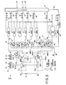
string 18 to be connected across resistors R4, R8, R12 and R16. - Figure 3 represents a detailed implementation of the switches and elements Z1 to Z6.
- In a preferred embodiment of the present invention, switches SW1 to SW8, SW4-2 and SW8-2 which are closed when A6 = 0 are transistors NMOS. Switches SW9 to SW16 and SW12-2 and SW16-2 which are closed when A6=1 are PMOS transistors.
- Only, the arrangement provided between nodes N6 and N7 are shown in figure 3.
- The gate of transistors T7 and T6 making up switches SW7 and SW6 are connected to the
output line 30 ofbit decoder 32, which is active when the condition A6.A5 = 1 is met. - Switches SW18-1 and SW18-2 have the same structure. Switch SW18-1 comprises NMOS transistor TN18-1 and PMOS transistor TP18-1 and switch SW18-2 comprises NMOS transistor TN18-2 and PMOS transistor TP18-2. These complementary transistors are parallely mounted and are serially mounted with MSB switch transistors T6, T7, as shown in figure 3.
- NMOS and PMOS transistors switch SW18 are made ON when the logical condition A4.A3 is met.
- Thus, the
corresponding output line 34 ofbit decoder 36 is provided to the gates of transistors TN18-2 and TN18-1. This line is also provided to inverters 118-1 and 118-2, the outputs of which are provided to the gates of PMOS transistors TP18-1 and TP18-2. - Elements Z1 to Z6 comprise NMOS transistor TNM and PMOS transistor TPM which are parallely mounted and the gate of which is connected to
output line 38 ofdecoder 30 activated when A6 is equal to 0. Thus, when A6 is equal to 0, TNM transistors of resistive elements Z1 to Z6 are ON to copy the impedance of the NMOS making up switches SW1 to SW8, SW4-2 and SW8-2. When A6 is equal to 1, TPM transistors of resistive elements Z1 to Z6 are ON to copy the impedance of the PMOS transistors making up switched SW9 to SW16, SW12-2 and SW16-2. - Transistors TNM and TPM in elements Z1 to Z6 must track NMOS and PMOS transistors making up
block 10. - Elements Z1 to Z6 also comprise NMOS transistor TNL and PMOS transistor TPL which are parallely mounted and arranged in series with transistors TNM and TPM. Transistors TNL ad TPL are arranged as transistors TN18 and TP18 making up switches SW18-1 and SW18-2.
- The gate of transistors TNL in elements Z1 to Z6 are connected to
output line 40 ofdecoder 42 through ORgate 22line 40 is at zero level when A2, A1 and AO are at 0, to causes transistors TNL of elements Z1 to Z6 to be off, to disconnect thestring 18 from nodes M1 and M7. -
Output line 41 of ORcircuit 22 is provided to inverters INV in elements Z1 to Z6, the output lines of which are provided to the gates of transistors TPL to cause these transistors to be OFF whenline 40 is at 0 level. - NMOS transistors TNL must track NMOS transistors of LSB switch UP and DOWN blocks 12 and 14. PMOS transistors TPL must track PMOS transistors of
blocks 12 and 14. - Output switches SW22 to SW28 have the same structures as switches SW 18-1 and 18-2, their gates are controlled by the output signals on
lines 44 to 50 ofdecoder 42 which are active when the logical conditions indicated in figures 2 and 3 are met. - This device may be used as a N-bit DAC N = 4, with a 7 bit accuracy, when the programming input PI provided to one input of
OR gate 22 is set to disconnect thestring 18 from nodes M1 and M7. - When the programming input PI is set to allow the connection the
string 18 between nodes M1 and M7, the resolution of N-bit DAC may be extended by P, with P = 3 as shown in figure 2. - The resolution may be extended by 2, by dividing the voltage across a selected resistor in
string 2 by 22 = 4. This may be done by connecting node M1, node M2, node M4 or node M6 tooutput 20, through the output switches SW22, SW23, SW25, SW27 controlled by the following values ofLSB bits - The resolution may be extended by 1, by dividing the voltage across a selected resistor in
string 2 by 2. This may be done by connecting nodes M1 and M4 tooutput 20, through output switches SW22 and SW25 controlled by thevalue - This also may be done by providing swiches which short together selected nodes M1 to M7 to M6 when closed, and taking the analog levels through switches SW22, SW27 or SW28 as the case may be. The concept described in reference to figures 2 and 3 may be extended to any value of N and P. Assuming N=n=m+ℓ, n being equal to any integer number, as described before, with 1 < I < n.
- The
resistor string 2 comprises x = 2" resistors R1 to Rx, x = 2" MSB switches inblock 10. 2t switches in LSB SWITCH UP and DOWN blocks 12 and 14.String 18 comprises 2P-2 elements where P is the maximum number of extension bits.Block 16 comprises 2p-1 output switches. - If ℓ=0, the function performed by block 14, will be performed through a switching
arrangement 60 comprising 2n switches SW1-1 to SW16-1 having the same impedance, when closed, as switches SW1 to SW16 inblock 10 and controlled by the same logical conditions as switches SW1 to SW16. Switches SW1-1 to SW16-1 have first terminals connected in common to node M7 and second terminals connected to taps N1-2 to N15-2 duplicating taps N2, to N16 of theresistor string 2 and the tap N16-2, respectively. In that case, when switches inblock 10 are made with NMOS and PMOS transistors, the resistive elements Z1 to Z6 only comprise NMOS and PMOS transistors TNM and TPM copying the NMOS or PMOS transistors inblock 10. - In any cases, assuming N equal to 8, and P equal 4, it may be possible, to build a 12-bit resolution DAC with 12 bit accuracy, a 8-bit resolution DAC with 12 bit accuracy, either by keeping the four LSB bits at a low level or by setting the programming input, or a 10-bit resolution DAC with a 12 bit accuracy by controlling selected ones of the output switches.
Claims (7)
Priority Applications (4)
| Application Number | Priority Date | Filing Date | Title |
|---|---|---|---|
| EP87480013A EP0310728B1 (en) | 1987-10-09 | 1987-10-09 | Device for extending the resolution of a n-bit resistive digital to analog converter to a (n+p)-bit digital to analog |
| DE8787480013T DE3781277D1 (en) | 1987-10-09 | 1987-10-09 | DEVICE FOR THE RESOLUTION EXPANSION OF AN N-BIT-OHMSCH DIGITAL-ANALOG-CONVERTER TO A (N + P) -BIT-DIGITAL-ANALOG-CONVERTER. |
| JP63177273A JPH0197020A (en) | 1987-10-09 | 1988-07-18 | Resolution power expanding device for analog -to-digital converter |
| US07/249,542 US4918448A (en) | 1987-10-09 | 1988-09-26 | Device for extending the resolution of a N-bit resistive digital-to-analog converter to a (N+P)-bit digital-to-analog converter |
Applications Claiming Priority (1)
| Application Number | Priority Date | Filing Date | Title |
|---|---|---|---|
| EP87480013A EP0310728B1 (en) | 1987-10-09 | 1987-10-09 | Device for extending the resolution of a n-bit resistive digital to analog converter to a (n+p)-bit digital to analog |
Publications (2)
| Publication Number | Publication Date |
|---|---|
| EP0310728A1 EP0310728A1 (en) | 1989-04-12 |
| EP0310728B1 true EP0310728B1 (en) | 1992-08-19 |
Family
ID=8198326
Family Applications (1)
| Application Number | Title | Priority Date | Filing Date |
|---|---|---|---|
| EP87480013A Expired - Lifetime EP0310728B1 (en) | 1987-10-09 | 1987-10-09 | Device for extending the resolution of a n-bit resistive digital to analog converter to a (n+p)-bit digital to analog |
Country Status (4)
| Country | Link |
|---|---|
| US (1) | US4918448A (en) |
| EP (1) | EP0310728B1 (en) |
| JP (1) | JPH0197020A (en) |
| DE (1) | DE3781277D1 (en) |
Families Citing this family (34)
| Publication number | Priority date | Publication date | Assignee | Title |
|---|---|---|---|---|
| US5200751A (en) * | 1989-06-26 | 1993-04-06 | Dallas Semiconductor Corp. | Digital to analog converter using a programmable logic array |
| JP2598138B2 (en) * | 1989-10-31 | 1997-04-09 | 株式会社東芝 | D / A converter |
| JPH04135323A (en) * | 1990-09-27 | 1992-05-08 | Nec Corp | Digital/analog converting circuit |
| JP2937452B2 (en) * | 1990-10-12 | 1999-08-23 | 日本電気株式会社 | Digital to analog converter |
| DE69222893T2 (en) * | 1991-06-18 | 1998-03-05 | Fujitsu Ltd | Digital-to-analog converter with resistor networks |
| US5283579A (en) * | 1992-03-06 | 1994-02-01 | Micro Power Systems, Inc. | Digital to analog converter having high multiplying bandwidth |
| US5396245A (en) * | 1993-01-21 | 1995-03-07 | Linear Technology Corporation | Digital to analog converter |
| US5823032A (en) * | 1994-04-07 | 1998-10-20 | The Boeing Company | Prethinning for superplastic forming |
| US5495245A (en) * | 1994-04-26 | 1996-02-27 | Analog Devices, Inc. | Digital-to-analog converter with segmented resistor string |
| US5554986A (en) * | 1994-05-03 | 1996-09-10 | Unitrode Corporation | Digital to analog coverter having multiple resistor ladder stages |
| US5617091A (en) * | 1994-09-02 | 1997-04-01 | Lowe, Price, Leblanc & Becker | Resistance ladder, D-A converter, and A-D converter |
| IT1289207B1 (en) * | 1996-10-24 | 1998-09-29 | Sgs Thomson Microelectronics | COMPENSATED MOS-RESISTIVE POTENTIOMETRIC STRING AND DIGITAL / ANALOG CONVERTER USING THIS STRING |
| US5969657A (en) * | 1997-07-22 | 1999-10-19 | Analog Devices, Inc. | Digital to analog converter |
| US5952948A (en) * | 1997-09-24 | 1999-09-14 | Townsend And Townsend And Crew Llp | Low power liquid-crystal display driver |
| US5940020A (en) * | 1997-10-09 | 1999-08-17 | Tritech Microelectronics, Ltd | Digital to analog converter with a reduced resistor count |
| US6441758B1 (en) | 1997-11-27 | 2002-08-27 | Semiconductor Energy Laboratory Co., Ltd. | D/A conversion circuit and semiconductor device |
| US5977898A (en) * | 1997-12-22 | 1999-11-02 | Texas Instruments Incorporated | Decoding scheme for a dual resistor string DAC |
| US5999115A (en) * | 1998-04-20 | 1999-12-07 | Motorola, Inc. | Segmented DAC using PMOS and NMOS switches for improved span |
| KR100282447B1 (en) | 1998-08-18 | 2001-02-15 | 김영환 | Nonlinear Digital / Analog Converter |
| US6252534B1 (en) * | 1999-01-14 | 2001-06-26 | Analog Devices, Inc. | Resistor string DAC with current mode interpolation |
| US6317069B1 (en) | 1999-05-06 | 2001-11-13 | Texas Instruments Incorporated | Digital-to-analog converter employing binary-weighted transistor array |
| US6414616B1 (en) | 2000-06-22 | 2002-07-02 | Analog Devices, Inc. | Architecture for voltage scaling DAC |
| GB0108656D0 (en) * | 2001-04-06 | 2001-05-30 | Koninkl Philips Electronics Nv | Digital to analogue converter |
| US7180966B2 (en) * | 2001-10-26 | 2007-02-20 | International Business Machines Corporation | Transition detection, validation and memorization circuit |
| JP4002147B2 (en) * | 2002-07-24 | 2007-10-31 | 沖電気工業株式会社 | Digital / analog conversion circuit |
| US6781536B1 (en) * | 2003-05-12 | 2004-08-24 | Texas Instruments Incorporated | Dual-stage digital-to-analog converter |
| US7034732B1 (en) * | 2004-12-30 | 2006-04-25 | Intel Corporation | Multi-stage digital-to-analog converter |
| KR100735493B1 (en) * | 2005-06-21 | 2007-07-04 | 삼성전기주식회사 | Digital/analog converter |
| US7161517B1 (en) * | 2005-06-29 | 2007-01-09 | Himax Technologies, Inc. | Digital-to-analog converter |
| KR20070005808A (en) * | 2005-07-06 | 2007-01-10 | 삼성전자주식회사 | Cooking apparatus, cooking system, cooking control method utilizing bar code |
| US7688240B2 (en) * | 2008-05-02 | 2010-03-30 | Analog Devices, Inc. | Method and apparatus for calibrating an RDAC for end-to-end tolerance correction of output resistance |
| JP2012160968A (en) | 2011-02-01 | 2012-08-23 | Advantest Corp | Digital/analog converter |
| US9124296B2 (en) * | 2012-06-27 | 2015-09-01 | Analog Devices Global | Multi-stage string DAC |
| CN105210298B (en) | 2013-03-15 | 2019-11-05 | 亚德诺半导体集团 | More string digital to analog converter |
Citations (1)
| Publication number | Priority date | Publication date | Assignee | Title |
|---|---|---|---|---|
| EP0123222A2 (en) * | 1983-04-18 | 1984-10-31 | Kabushiki Kaisha Toshiba | Digital-to-analog converter |
Family Cites Families (7)
| Publication number | Priority date | Publication date | Assignee | Title |
|---|---|---|---|---|
| US3997892A (en) * | 1973-07-27 | 1976-12-14 | Trw Inc. | Digital to analog converter with improved companding |
| DE2532580C3 (en) * | 1975-07-21 | 1980-06-04 | Siemens Ag, 1000 Berlin Und 8000 Muenchen | Circuit arrangement for setting electrical or electromagnetic quantities and time periods determined by electrical switching means |
| JPS5384452A (en) * | 1976-12-29 | 1978-07-25 | Fujitsu Ltd | D/a donverter |
| JPS56146326A (en) * | 1980-04-16 | 1981-11-13 | Sanyo Electric Co Ltd | Digital-to-analog converter |
| JPS57194625A (en) * | 1981-05-27 | 1982-11-30 | Nec Corp | Digital to analog converter |
| US4491825A (en) * | 1981-06-09 | 1985-01-01 | Analog Devices, Incorporated | High resolution digital-to-analog converter |
| US4543560A (en) * | 1984-02-17 | 1985-09-24 | Analog Devices, Incorporated | Two-stage high resolution digital-to-analog converter |
-
1987
- 1987-10-09 DE DE8787480013T patent/DE3781277D1/en not_active Expired - Lifetime
- 1987-10-09 EP EP87480013A patent/EP0310728B1/en not_active Expired - Lifetime
-
1988
- 1988-07-18 JP JP63177273A patent/JPH0197020A/en active Granted
- 1988-09-26 US US07/249,542 patent/US4918448A/en not_active Expired - Fee Related
Patent Citations (1)
| Publication number | Priority date | Publication date | Assignee | Title |
|---|---|---|---|---|
| EP0123222A2 (en) * | 1983-04-18 | 1984-10-31 | Kabushiki Kaisha Toshiba | Digital-to-analog converter |
Also Published As
| Publication number | Publication date |
|---|---|
| EP0310728A1 (en) | 1989-04-12 |
| US4918448A (en) | 1990-04-17 |
| DE3781277D1 (en) | 1992-09-24 |
| JPH0320933B2 (en) | 1991-03-20 |
| JPH0197020A (en) | 1989-04-14 |
Similar Documents
| Publication | Publication Date | Title |
|---|---|---|
| EP0310728B1 (en) | Device for extending the resolution of a n-bit resistive digital to analog converter to a (n+p)-bit digital to analog | |
| JP3828667B2 (en) | Digital / analog converter | |
| EP0102609B1 (en) | Digital-analog converter | |
| US5731774A (en) | Digital-to-analog converter | |
| US6914547B1 (en) | Triple resistor string DAC architecture | |
| US4198622A (en) | Double digital-to-analog converter | |
| US6714151B2 (en) | A/D converter | |
| EP0521629B1 (en) | Digital-to-analog converter having resistor networks | |
| EP0249986A2 (en) | Analog-to-digital converter | |
| WO2002082658A2 (en) | Digital to analogue converter | |
| WO1992011698A1 (en) | Digital-to-analog and analog-to-digital converters | |
| JP2001244816A (en) | Digitally switched potentiometer with improved linearity and setting time | |
| JPH08237128A (en) | Digital to analogue converter with redused resistane number | |
| WO2008055139A2 (en) | Digital-to-analog converter architecture and method having low switch count and small output impedance | |
| US20120032828A1 (en) | Coarse digital-to-analog converter architecture for voltage interpolation dac | |
| EP1813020B1 (en) | Balanced dual resistor string digital to analog converter system and method | |
| US20060261991A1 (en) | Digital-to-analog converter | |
| EP0661817B1 (en) | Digital-to-analog converter | |
| JP2791519B2 (en) | Binary data generation circuit and A / D converter | |
| JP2598138B2 (en) | D / A converter | |
| US7046182B1 (en) | DAC having switchable current sources and resistor string | |
| EP0135274A2 (en) | Digital-to-analog converter | |
| US4803461A (en) | R-2R type D/A converter circuit | |
| EP0681372B1 (en) | Digital-to-analog conversion circuit and analog-to-digital conversion device using the circuit | |
| JPH0222571B2 (en) |
Legal Events
| Date | Code | Title | Description |
|---|---|---|---|
| PUAI | Public reference made under article 153(3) epc to a published international application that has entered the european phase |
Free format text: ORIGINAL CODE: 0009012 |
|
| AK | Designated contracting states |
Kind code of ref document: A1 Designated state(s): DE FR GB |
|
| 17P | Request for examination filed |
Effective date: 19890809 |
|
| 17Q | First examination report despatched |
Effective date: 19900914 |
|
| GRAA | (expected) grant |
Free format text: ORIGINAL CODE: 0009210 |
|
| AK | Designated contracting states |
Kind code of ref document: B1 Designated state(s): DE FR GB |
|
| PG25 | Lapsed in a contracting state [announced via postgrant information from national office to epo] |
Ref country code: DE Effective date: 19920819 |
|
| REF | Corresponds to: |
Ref document number: 3781277 Country of ref document: DE Date of ref document: 19920924 |
|
| ET | Fr: translation filed | ||
| PGFP | Annual fee paid to national office [announced via postgrant information from national office to epo] |
Ref country code: FR Payment date: 19920928 Year of fee payment: 6 |
|
| PG25 | Lapsed in a contracting state [announced via postgrant information from national office to epo] |
Ref country code: GB Effective date: 19921119 |
|
| PLBE | No opposition filed within time limit |
Free format text: ORIGINAL CODE: 0009261 |
|
| STAA | Information on the status of an ep patent application or granted ep patent |
Free format text: STATUS: NO OPPOSITION FILED WITHIN TIME LIMIT |
|
| GBPC | Gb: european patent ceased through non-payment of renewal fee |
Effective date: 19921119 |
|
| 26N | No opposition filed | ||
| PG25 | Lapsed in a contracting state [announced via postgrant information from national office to epo] |
Ref country code: FR Effective date: 19940630 |
|
| REG | Reference to a national code |
Ref country code: FR Ref legal event code: ST |