EP0309655A2 - Image processing apparatus and method - Google Patents
Image processing apparatus and method Download PDFInfo
- Publication number
- EP0309655A2 EP0309655A2 EP88110385A EP88110385A EP0309655A2 EP 0309655 A2 EP0309655 A2 EP 0309655A2 EP 88110385 A EP88110385 A EP 88110385A EP 88110385 A EP88110385 A EP 88110385A EP 0309655 A2 EP0309655 A2 EP 0309655A2
- Authority
- EP
- European Patent Office
- Prior art keywords
- image data
- directional
- endpoint
- original image
- data
- Prior art date
- Legal status (The legal status is an assumption and is not a legal conclusion. Google has not performed a legal analysis and makes no representation as to the accuracy of the status listed.)
- Granted
Links
Images


Classifications
-
- H—ELECTRICITY
- H04—ELECTRIC COMMUNICATION TECHNIQUE
- H04N—PICTORIAL COMMUNICATION, e.g. TELEVISION
- H04N1/00—Scanning, transmission or reproduction of documents or the like, e.g. facsimile transmission; Details thereof
- H04N1/41—Bandwidth or redundancy reduction
- H04N1/411—Bandwidth or redundancy reduction for the transmission or storage or reproduction of two-tone pictures, e.g. black and white pictures
- H04N1/413—Systems or arrangements allowing the picture to be reproduced without loss or modification of picture-information
- H04N1/419—Systems or arrangements allowing the picture to be reproduced without loss or modification of picture-information in which encoding of the length of a succession of picture-elements of the same value along a scanning line is the only encoding step
-
- G—PHYSICS
- G06—COMPUTING; CALCULATING OR COUNTING
- G06T—IMAGE DATA PROCESSING OR GENERATION, IN GENERAL
- G06T9/00—Image coding
- G06T9/005—Statistical coding, e.g. Huffman, run length coding
Definitions
- the present invention relates to an image processing apparatus for carrying out image processes such as a horizontal-to-vertical converting operation to convert an input image represented with first directional run length codes into an image represented with second directional run length codes.
- a run length coding method is widely used in various image processing apparatuses such as facsimiles to compress image data.
- an original image is subjected to a raster scanning operation to obtain binary image data.
- the binary image data are used to make a bit map, each line of the bit map comprising black dots and white dots.
- the length (run length) of a series of consecutive black dots hereinafter referred to as a "black run”
- the length of a series of consecutive white dots hereinafter referred to as a "white run” as well as positional information of endpoints of the black and white runs are coded with run length codes.
- each run length code comprises, for instance, eight bits.
- a first bit of the eight-bit code is a flag for indicating whether a run is white (0) or black (1), and the remaining bits of the code indicating the length of the run. Supposing a data comprises two consecutive white dots, three consecutive black dots and two consecutive white dots, the data will be coded as "02, 83, 02" in hexadecimal notation.
- horizontal and vertical run length data are frequently used to extract linear elements from an input image or to remove noises from the input image.
- horizontal and vertical black runs are used as information to find horizontal and vertical projections.
- the run length coding is generally carried out for the same direction as that of raster scan which takes place, for instance in a horizontal direction. Therefore, to obtain information of vertical components, coded horizontal run data shall be decoded into an original bit map (binary image data), and based on which vertical run length codes shall be prepared to obtain vertical projections, etc. Due to this, an image memory needed for the method shall have a large capacity. Further, the process to obtain vertical components shall be carried out for every pixel so that the number of memory accesses and the number of computation may be increased to extend an operation time.
- the conventional image processing apparatus requires a large memory capacity and takes a long time in carrying out an image process such as the horizontal-to-vertical converting operation to obtain run length codes for a direction different from a scanning direction.
- An object of the present invention is to provide an image processing apparatus which can obtain run length codes for a direction different from a scanning direction at a high speed and with a small memory capacity.
- Another object of the present invention is to provide an image processing apparatus which codes original image data with run length codes for a first direction to obtain input image data and, without decoding the input image data into the original image data again, processes the input image data as they are to detect endpoint positions for a second direction.
- an image processing apparatus which encodes an original image with run length codes for a first direction to obtain input image data and carries out an exclusive OR operation on the data of adjacent two lines of the input image data to detect endpoints for a second direction which is different from the first direction.
- the apparatus comprises an input image memory for storing the input image data obtained by coding the original image data with the run length codes for the first direction, a reading circuit for sequentially reading from the input image memory the inputted image data of the two lines which are adjacent to each other in the second direction orthogonal to the first direction, an exclusive OR processing circuit for carrying out an exclusive OR operation on the input image data of the adjacent two lines sequentially read by the reading device without decoding the data into the original image data to detect endpoint positions for the second direction of the original image data, and a second directional processing circuit for carrying out a predetermined image process for the second direction according to the endpoint positions for the second direction detected by the exclusive OR processing circuit.
- the data of adjacent two lines of the input image data are subjected to the exclusive OR operation to extract positions where the run length codes are different from each other to detect endpoint positions for the second direction. Once the endpoint positions for the second direction are detected, an image process for the second direction may be easily performed.
- the input image data coded with run length codes are not decoded into the original image data but processed as they are to detect the endpoint positions for the second direction, thereby realizing a high-speed process with a small memory capacity.
- Figs. 1 to 7 are views for explaining a horizontal-to-vertical conversion processing apparatus according to an embodiment of the present invention.
- the apparatus is for converting horizontal runs (runs in a first direction) into vertical runs (runs in a second direction).
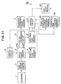
- Fig. 1 is a block diagram showing the constitution of the apparatus.
- a scanner 1 carries out a raster scanning operation on an original image to output binary image data as original image data.
- a run length coding circuit 2 sequentially encodes the binary image data with run length codes to provide horizontal run length data which are outputted as input image data to an input image memory 3.
- the input image memory 3 stores the input image data transferred from the run length coding circuit 2.
- a first-line flag memory 4 is a register for storing flags only in the first line data among the input image data stored in the input image memory 3.
- a control circuit 5 specifies a read address with respect to the input image memory 3 to read the data of adjacent two lines, i.e., a line "j-1" and a line "j" from the input image memory 3.
- the data of the lines j-1 and j sequentially read out of the input image memory 3 under the control of the control circuit 5 are given to an exclusive logical add processing circuit (hereinafter referred to as the "EX-OR processing circuit") 6.
- the EX-OR processing circuit 6 carries out an exclusive OR operation on the data of the lines j-1 and j to detect endpoint coordinate values for a vertical direction.
- An endpoint coordinate value memory 7 stores the endpoint coordinate values detected in the EX-OR processing circuit 6.
- a first-run flag memory 8 is a register for storing flags of first runs of respective lines detected in the EX-OR processing circuit 6.
- a control circuit 9 properly reads data of the endpoint coordinate value memory 7 and of the first-run flag memory 8 to provide the read data to a vertical run conversion processing circuit 10 which is the second directional processing means, and gives a read timing to the control circuit 5 to read the input image memory 3.
- the vertical run conversion processing circuit 10 comprises an endpoint count memory 11, an endpoint coordinate value memory 12, a run length coding circuit 13 and a run length code memory 14.
- the endpoint count memory 11 stores the numbers of endpoints for a vertical direction in each column of the input image data.
- the endpoint coordinate value memory 12 is a memory for storing coordinate values of the vertical endpoints of each column.
- the run length coding circuit 13 receives the numbers of endpoints of the respective columns from the endpoint count memory 11, the endpoint coordinate values of the respective columns from the endpoint coordinate value memory 12 and the flags of respective runs in the first line from the first-line flag memory 4 to carry out the vertical run length coding operation.
- the run length code memory 14 is a memory for storing the vertical run length codes prepared in the run length coding circuit 13.
- Original image data read by the scanner 1 are encoded with run length codes for the horizontal direction in the run length coding circuit 2.
- Each run length code comprises, for instance, one byte (eight bits) as shown in Fig. 2.
- a first bit of the code is a flag for identifying that a run is white (0) or black (1).
- the following 7 bits indicate the length of the run.
- lines j-1, j and j+1 of the original image data shown in Fig. 3 are coded with run length codes as indicated with hexadecimal numerals in the right side of the figure. These run length codes are stored for each line in the input image memory 3.
- the input image data for adjacent two lines are sequentially read and transferred to the EX-OR processing circuit 6 for an endpoint detection process.
- Fig. 4 is a view showing an example of the constitution of the EX-OR processing circuit 6.
- the run length codes for the lines j-1 and j are given to endpoint coordinate value detecting circuits 21 and 22 respectively to find endpoint coordinate values for the horizontal direction.
- the horizontal endpoint coordinate values of the respective lines thus found are stored in endpoint coordinate value memories 23 and 24.
- the endpoint coordinate values stored in the memories 23 and 24 are given to and sorted in a sorting circuit 25.
- the sorting circuit 25 abandons the values and, when the memories 23 and 24 provide different values, the circuit 25 sorts the values.
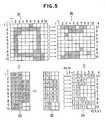
- Fig. 5 shows various processing sates of image data.
- input image data 32 represented with run length codes for the horizontal direction.
- the run length codes are converted into horizontal coordinate values (i) to obtain data 33.
- Only different values in adjacent two lines among the data 33 are arranged in an ascending order, and a line head number "1" is added to the head of the arranged line while a line tail number plus one, i.e., "11" is added to the tail of the arranged line to obtain output data 34.
- the output data 34 are stored in the endpoint coordinate value memory 7.
- the output data 34 may correspond to image data 35 shown in Fig. 5. Comparing the image data 35 with the original image data 31, it will be seen that the image data 35 have bits at changing points where dots change from white to black or from black to white. Namely, the image data 35 indicate endpoint positions for the vertical direction.
- a first-run flag EX-OR circuit 26 shown in Fig. 4 extracts first-run flags of the lines j-1 and j to carry out the exclusive OR operation on the extracted flags and output the results to the first-run flag memory 8.
- the endpoint count memory 11 is a one-dimensional memory corresponding to one line of the original image data.
- the contents of the memory 11 are represented with N(i).
- the endpoint coordinate value memory 12 is a two-dimensional memory having a capacity of storing vertical endpoints for every line of the original image data.
- the contents of the memory 12 are represented with J(i, k).
- the endpoint coordinate value memory 7 shown in Fig. 1 is a one-dimensional memory of which contents are represented with K( l , k) where "k" indicates a current processing point.
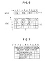
- the run length coding circuit 13 refers to the first flag data stored in the first-line flag memory 4 and the endpoint coordinate value data in the endpoint coordinate value memory 12 to provide vertical run length codes. As a result, vertical run length codes as shown in Fig. 7 are obtained and stored in the run length code memory 14.
- the coordinate values of all lines may be stored in the endpoint coordinate value memory 7 before starting the vertical run converting process. Further, it is possible to perform the vertical run length coding operation for every registering operation into the endpoint coordinate value memory 12.
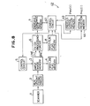
- Figs. 8 to 10 are views showing a vertical projection detector according to another embodiment of the present invention.
- a vertical projection detecting circuit 42 which is used as the second directional processing means comprises a previous change position memory 43 and a vertical projection memory 44.
- the previous change position memory 43 and the vertical projection memory 44 are one-dimensional memories respectively each having a capacity of storing one line of original image data.
- the contents of the memories 43 and 44 are represented with Prev(i) and Proj(i) respectively.
- Flags of a first line in the first-line flag memory 4 are checked, and "i"s of the Prev(i) of the previous change position memory 43 are initially filled with 1s (the "1" representing the first line) for black runs and with 0s for white runs.
- a control circuit 41 reads the endpoint coordinate value memory 7 according to the value of a flag of a first run as in the case of the previous embodiment.
- a value Prev(i) is positive, it means that a vertical run in the line in question has been changed from black to white, and the positive value indicates a position where a previous change from white to black has occurred.
- the Proj(i) indicates the projection value of a column "i".
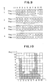
- the vertical projection memory 44 stores vertical projection data of the original image as shown in Fig. 10.
- the previous change position memory 43 has stored the starting point coordinate values of vertical black runs, it is possible to obtain the vertical projection by subtracting change position coordinate values from the vertical projection memory Proj(i) when the vertical run changes from white to black, and by adding change position coordinate values to the Proj(i) when the vertical run changes from black to white.
- Figs. 11 to 13 are views showing a vertical component extracting apparatus according to still another embodiment of the present invention.
- a vertical component extracting circuit 52 which is used as the second directional processing means comprises a previous change position memory 53, an extracted run position memory 54 and a run count memory 55.
- the previous change position memory 53 is a memory having the same function as that of the previous change position memory 43.
- the extracted run position memory 54 is a two-dimensional memory having a capacity of storing extracted runs for three lines. The contents of the memory 54 are represented with Run(m, n).
- the run count memory 55 is a memory for storing the number "n" of runs to be extracted and has an initial value of 0.
- the contents Prev(i) of the previous change position memory 53 are initialized.
- a control circuit 51 reads the endpoint coordinate value memory 7 according to the value of a flag of a first run. Supposing endpoint coordinate values K( l 1, k1) and K( l 2, k1) have been read, the data Prev(i) for "i"s satisfying K( l 1, K1) ⁇ i ⁇ K( l 2, k1) are read from the previous change position memory 53. Among the read data, runs with "i"s satisfying K1 - Prev(i) > th ("th" indicating a predetermined run length threshold) are registered as extracted runs.
- this registration is carried out by reading "n” from the run count memory 55, by incrementing the value, and by registering a column number "i” into a Run(1, n) of the extracted run position memory 54, Prev(i) into a Run(2, n) and k-1 into a Run(3, n).
- a column number "i” of the extracted run is registered into the Run(1, n), a starting point line position of the extracted run into the Run(2, n), and an endpoint line position of the extracted run into the Run(3, n).
- Prev(i) are read and, for all "i"s satisfying kmax + 1 - Prev(i) > th among "i"s satisfying Prev(i) > 0, the line count memory 55 is read and incremented while a column number "i" is registered into a Run(1, n), a Prev(i) into a Run(2, n) and the kmax into a Run(3, n) to complete the operation.
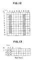
- vertical runs having run lengths longer than the predetermined run length are extracted as shown in Fig. 12.
- the contents of the extracted run position memory 54 are as shown in Fig. 13.
- run length codes for a first direction are subjected to an exclusive OR operation to find endpoint coordinate values for a second direction which is different from the first direction.
- an optional image process is carried out for the second direction so that a high-speed image processing is realized with a small capacity memory.
Landscapes
- Engineering & Computer Science (AREA)
- Multimedia (AREA)
- Signal Processing (AREA)
- Physics & Mathematics (AREA)
- General Physics & Mathematics (AREA)
- Theoretical Computer Science (AREA)
- Image Processing (AREA)
- Compression Of Band Width Or Redundancy In Fax (AREA)
- Image Analysis (AREA)
- Editing Of Facsimile Originals (AREA)
Abstract
Description
- The present invention relates to an image processing apparatus for carrying out image processes such as a horizontal-to-vertical converting operation to convert an input image represented with first directional run length codes into an image represented with second directional run length codes.
- A run length coding method is widely used in various image processing apparatuses such as facsimiles to compress image data. According to the run length coding method, an original image is subjected to a raster scanning operation to obtain binary image data. The binary image data are used to make a bit map, each line of the bit map comprising black dots and white dots. The length (run length) of a series of consecutive black dots (hereinafter referred to as a "black run") and the length of a series of consecutive white dots (hereinafter referred to as a "white run") as well as positional information of endpoints of the black and white runs are coded with run length codes.
- In a simple run length coding method, each run length code comprises, for instance, eight bits. A first bit of the eight-bit code is a flag for indicating whether a run is white (0) or black (1), and the remaining bits of the code indicating the length of the run. Supposing a data comprises two consecutive white dots, three consecutive black dots and two consecutive white dots, the data will be coded as "02, 83, 02" in hexadecimal notation.
- Meanwhile, horizontal and vertical run length data are frequently used to extract linear elements from an input image or to remove noises from the input image. For instance, in a handwritten character recognition apparatus, horizontal and vertical black runs are used as information to find horizontal and vertical projections.
- The run length coding is generally carried out for the same direction as that of raster scan which takes place, for instance in a horizontal direction. Therefore, to obtain information of vertical components, coded horizontal run data shall be decoded into an original bit map (binary image data), and based on which vertical run length codes shall be prepared to obtain vertical projections, etc. Due to this, an image memory needed for the method shall have a large capacity. Further, the process to obtain vertical components shall be carried out for every pixel so that the number of memory accesses and the number of computation may be increased to extend an operation time.
- As described in the above, the conventional image processing apparatus requires a large memory capacity and takes a long time in carrying out an image process such as the horizontal-to-vertical converting operation to obtain run length codes for a direction different from a scanning direction.
- An object of the present invention is to provide an image processing apparatus which can obtain run length codes for a direction different from a scanning direction at a high speed and with a small memory capacity.
- Another object of the present invention is to provide an image processing apparatus which codes original image data with run length codes for a first direction to obtain input image data and, without decoding the input image data into the original image data again, processes the input image data as they are to detect endpoint positions for a second direction.
- In order to accomplish the objects and advantages mentioned in the above, according to one aspect of the present invention, there is provided an image processing apparatus which encodes an original image with run length codes for a first direction to obtain input image data and carries out an exclusive OR operation on the data of adjacent two lines of the input image data to detect endpoints for a second direction which is different from the first direction. The apparatus comprises an input image memory for storing the input image data obtained by coding the original image data with the run length codes for the first direction, a reading circuit for sequentially reading from the input image memory the inputted image data of the two lines which are adjacent to each other in the second direction orthogonal to the first direction, an exclusive OR processing circuit for carrying out an exclusive OR operation on the input image data of the adjacent two lines sequentially read by the reading device without decoding the data into the original image data to detect endpoint positions for the second direction of the original image data, and a second directional processing circuit for carrying out a predetermined image process for the second direction according to the endpoint positions for the second direction detected by the exclusive OR processing circuit.
- In adjacent two lines of the input image data coded with the run length codes for the first direction, if both the lines have the same run length codes, it means that there is no endpoints for the second direction in the lines. If the run length codes of the two lines are different from each other, it means that there are endpoints for the second direction at positions where the run length codes are different from each other.
- In the apparatus according to the present invention, the data of adjacent two lines of the input image data are subjected to the exclusive OR operation to extract positions where the run length codes are different from each other to detect endpoint positions for the second direction. Once the endpoint positions for the second direction are detected, an image process for the second direction may be easily performed.
- As described in the above, according to the apparatus of the present invention, the input image data coded with run length codes are not decoded into the original image data but processed as they are to detect the endpoint positions for the second direction, thereby realizing a high-speed process with a small memory capacity.
- These and other objects, features and advantages of the present invention will become apparent from the following descriptions of preferred embodiments taken in conjunction with the accompanying drawings.
-
- Fig. 1 is a block diagram showing the constitution of a horizontal-to-vertical conversion processing apparatus according to an embodiment of the present invention;
- Fig. 2 is a view showing the structure of a run length code;
- Fig. 3 is a view showing a run length coding process;
- Fig. 4 is a block diagram showing the details of an exclusive OR processing circuit of the apparatus shown in Fig. 1;
- Fig. 5 is a view for explaining processes carried out in the circuit shown in Fig. 4;
- Fig. 6 is a view for explaining a vertical run length coding process carried out in the apparatus shown in Fig. 1;
- Fig. 7 is a view showing vertical runs obtained according to the process shown in Fig. 6;
- Fig. 8 is a block diagram showing the general constitution of a vertical projection detecting apparatus according to another embodiment of the present invention;
- Fig. 9 is a view for explaining a projection detecting process carried out in the apparatus shown in Fig. 8;
- Fig. 10 is a view diagrammatically showing vertical projections obtained according to the process shown in Fig. 9;
- Fig. 11 is a block diagram showing the general constitution of a vertical component extracting apparatus according to still another embodiment of the present invention;
- Fig. 12 is a view showing vertical runs extracted with the apparatus shown in Fig. 11; and
- Fig. 13 is a view showing the contents of an extracted run position memory.
- Figs. 1 to 7 are views for explaining a horizontal-to-vertical conversion processing apparatus according to an embodiment of the present invention. The apparatus is for converting horizontal runs (runs in a first direction) into vertical runs (runs in a second direction).
- Fig. 1 is a block diagram showing the constitution of the apparatus. A
scanner 1 carries out a raster scanning operation on an original image to output binary image data as original image data. A runlength coding circuit 2 sequentially encodes the binary image data with run length codes to provide horizontal run length data which are outputted as input image data to aninput image memory 3. Theinput image memory 3 stores the input image data transferred from the runlength coding circuit 2. A first-line flag memory 4 is a register for storing flags only in the first line data among the input image data stored in theinput image memory 3. Acontrol circuit 5 specifies a read address with respect to theinput image memory 3 to read the data of adjacent two lines, i.e., a line "j-1" and a line "j" from theinput image memory 3. - The data of the lines j-1 and j sequentially read out of the
input image memory 3 under the control of thecontrol circuit 5 are given to an exclusive logical add processing circuit (hereinafter referred to as the "EX-OR processing circuit") 6. TheEX-OR processing circuit 6 carries out an exclusive OR operation on the data of the lines j-1 and j to detect endpoint coordinate values for a vertical direction. An endpointcoordinate value memory 7 stores the endpoint coordinate values detected in the EX-ORprocessing circuit 6. A first-run flag memory 8 is a register for storing flags of first runs of respective lines detected in the EX-ORprocessing circuit 6. - A
control circuit 9 properly reads data of the endpointcoordinate value memory 7 and of the first-run flag memory 8 to provide the read data to a vertical runconversion processing circuit 10 which is the second directional processing means, and gives a read timing to thecontrol circuit 5 to read theinput image memory 3. - The vertical run
conversion processing circuit 10 comprises anendpoint count memory 11, an endpointcoordinate value memory 12, a runlength coding circuit 13 and a runlength code memory 14. Theendpoint count memory 11 stores the numbers of endpoints for a vertical direction in each column of the input image data. The endpointcoordinate value memory 12 is a memory for storing coordinate values of the vertical endpoints of each column. The runlength coding circuit 13 receives the numbers of endpoints of the respective columns from theendpoint count memory 11, the endpoint coordinate values of the respective columns from the endpointcoordinate value memory 12 and the flags of respective runs in the first line from the first-line flag memory 4 to carry out the vertical run length coding operation. The runlength code memory 14 is a memory for storing the vertical run length codes prepared in the runlength coding circuit 13. - An operation of the horizontal-to-vertical conversion processing apparatus with the above-mentioned arrangement will be described.
- Original image data read by the
scanner 1 are encoded with run length codes for the horizontal direction in the runlength coding circuit 2. Each run length code comprises, for instance, one byte (eight bits) as shown in Fig. 2. A first bit of the code is a flag for identifying that a run is white (0) or black (1). The following 7 bits indicate the length of the run. In the runlength coding circuit 2, lines j-1, j and j+1 of the original image data shown in Fig. 3 are coded with run length codes as indicated with hexadecimal numerals in the right side of the figure. These run length codes are stored for each line in theinput image memory 3. - From the
input image memory 3, the input image data for adjacent two lines are sequentially read and transferred to theEX-OR processing circuit 6 for an endpoint detection process. - Fig. 4 is a view showing an example of the constitution of the
EX-OR processing circuit 6. The run length codes for the lines j-1 and j are given to endpoint coordinatevalue detecting circuits value memories memories sorting circuit 25. - When the
memories circuit 25, the sortingcircuit 25 abandons the values and, when thememories circuit 25 sorts the values. The sorting process is carried out from j=2 up to j=jmax. - Fig. 5 shows various processing sates of image data. Based on
original image data 31, there are obtainedinput image data 32 represented with run length codes for the horizontal direction. The run length codes are converted into horizontal coordinate values (i) to obtaindata 33. Only different values in adjacent two lines among thedata 33 are arranged in an ascending order, and a line head number "1" is added to the head of the arranged line while a line tail number plus one, i.e., "11" is added to the tail of the arranged line to obtainoutput data 34. Theoutput data 34 are stored in the endpoint coordinatevalue memory 7. - The
output data 34 may correspond to imagedata 35 shown in Fig. 5. Comparing theimage data 35 with theoriginal image data 31, it will be seen that theimage data 35 have bits at changing points where dots change from white to black or from black to white. Namely, theimage data 35 indicate endpoint positions for the vertical direction. - A first-run
flag EX-OR circuit 26 shown in Fig. 4 extracts first-run flags of the lines j-1 and j to carry out the exclusive OR operation on the extracted flags and output the results to the first-runflag memory 8. - Referring to Figs. 6 and 7, a vertical run length coding process will be described.
- The
endpoint count memory 11 is a one-dimensional memory corresponding to one line of the original image data. The contents of thememory 11 are represented with N(i). The endpoint coordinatevalue memory 12 is a two-dimensional memory having a capacity of storing vertical endpoints for every line of the original image data. The contents of thememory 12 are represented with J(i, k). The endpoint coordinatevalue memory 7 shown in Fig. 1 is a one-dimensional memory of which contents are represented with K( ℓ , k) where "k" indicates a current processing point. - As initial values of the
endpoint count memory 11, 1s are set in the N(i) (i=1 to imax). Also, as initial values of the endpoint coordinatevalue memory 12, 1s are set in the J(i, 1) (i=1 to imax). When k=2 is set, thecontrol circuit 9 reads a flag of the line k from the first-runflag memory 8. If the flag is 1, end point coordinate values are read out of the endpoint coordinatevalue memory 7 in the order of:
{K(1, k), K(2, k)}, {K(3, k), K(4, k)}, ..., and if the flag is 0, the end point coordinate values are read out of the endpoint coordinatevalue memory 7 in the order of:
{K(2, k), K(3, k)}, {K(4, k), K(5, k)}, ... Supposing {K(2, 2), K(3, 2)} = (2, 6) shown in Fig. 5 have been read, the data N(i) for "1"s (2, 3, 4 and 5) satisfying K(2, 2) ≦ i K(3, 2) are read from theendpoint count memory 11, and the read data N(i) are incremented and stored again. At the same time, the line number k (=2) is registered in corresponding J(i, k), i.e., J(2, 2) to J(5, 2). - Fig. 6 is a view showing a state that the above-mentioned operation has been carried out up to k=4 for the data shown in Fig. 5.
- The above-mentioned operation is repeated up to k=kmax (=10) to increment the data N(i) for all "i"s satisfying 1 ≦ i ≦ imax, and a value of kmax + 1 is registered in J(i, N(i)). Accordingly, the numbers of vertical endpoints are registered in the
endpoint count memory 11 while all the vertical endpoint coordinate values are registered in the endpoint coordinatevalue memory 12. - The run
length coding circuit 13 refers to the first flag data stored in the first-line flag memory 4 and the endpoint coordinate value data in the endpoint coordinatevalue memory 12 to provide vertical run length codes. As a result, vertical run length codes as shown in Fig. 7 are obtained and stored in the runlength code memory 14. - Although the endpoint coordinate values J(i, k) have been registered for each storage of the data of one line in the endpoint coordinate
value memory 7 and, after the storage, thecontrol circuit 9 requested thecontrol circuit 5 to read the next data, the coordinate values of all lines may be stored in the endpoint coordinatevalue memory 7 before starting the vertical run converting process. Further, it is possible to perform the vertical run length coding operation for every registering operation into the endpoint coordinatevalue memory 12. - Figs. 8 to 10 are views showing a vertical projection detector according to another embodiment of the present invention.
- As shown in Fig. 8, a vertical
projection detecting circuit 42 which is used as the second directional processing means comprises a previouschange position memory 43 and avertical projection memory 44. The previouschange position memory 43 and thevertical projection memory 44 are one-dimensional memories respectively each having a capacity of storing one line of original image data. The contents of thememories - Flags of a first line in the first-
line flag memory 4 are checked, and "i"s of the Prev(i) of the previouschange position memory 43 are initially filled with 1s (the "1" representing the first line) for black runs and with 0s for white runs. The Proj(i) (i=1 to imax) of thevertical projection memory 44 are initially filled with 0s. Acontrol circuit 41 reads the endpoint coordinatevalue memory 7 according to the value of a flag of a first run as in the case of the previous embodiment. - Supposing endpoint coordinate values K(
ℓ 1, k1) and K(ℓ 2, K1) have been read, the data Prev(i) for all "i"s satisfying K(ℓ 1, k1) ≦ i < K(ℓ 2, k1) are read from the previouschange position memory 43. For the "i"s satisfying Prev(i) > 0 among the read data, vertical run lengths "k1-Prev(i)" are added to the Proj(i) stored in thevertical projection memory 44, and the data Prev(i) for the above-mentioned "i"s are reset to 0s. For "i"s satisfying "Prev(i)=0", the values of Prev(i) are changed to k. Namely, if a value Prev(i) is positive, it means that a vertical run in the line in question has been changed from black to white, and the positive value indicates a position where a previous change from white to black has occurred. The Proj(i) indicates the projection value of a column "i". - Fig. 9 is a view showing that the above-mentioned process has been carried out for the data shown in Fig. 5 up to k=4. when k=1, the Prev(i) and Proj(i) are set with initial values. When k=2, the Prev(i) for i=2 to 5, 7 and 8 are 0s respectively so that these Prev(i) are filled with k=2. When k=3, the Prev(i) for i=4 to 7 are larger than 0 so that the Proj(i) corresponding to these "i"s are added with values of k(=3) - Prev(i) respectively. After carrying out the above-mentioned operation up to k=kmax, Prev(i) are read and, for all "i"s satisfying Prev(i) > 0, kmax + 1 - Prev(i) are added to the Proj(i) to complete the operation. As a result, the
vertical projection memory 44 stores vertical projection data of the original image as shown in Fig. 10. - Although the previous
change position memory 43 has stored the starting point coordinate values of vertical black runs, it is possible to obtain the vertical projection by subtracting change position coordinate values from the vertical projection memory Proj(i) when the vertical run changes from white to black, and by adding change position coordinate values to the Proj(i) when the vertical run changes from black to white. - Figs. 11 to 13 are views showing a vertical component extracting apparatus according to still another embodiment of the present invention.
- As shown in Fig. 11, a vertical
component extracting circuit 52 which is used as the second directional processing means comprises a previouschange position memory 53, an extractedrun position memory 54 and arun count memory 55. The previouschange position memory 53 is a memory having the same function as that of the previouschange position memory 43. The extractedrun position memory 54 is a two-dimensional memory having a capacity of storing extracted runs for three lines. The contents of thememory 54 are represented with Run(m, n). Therun count memory 55 is a memory for storing the number "n" of runs to be extracted and has an initial value of 0. - Similar to the previous embodiment, the contents Prev(i) of the previous
change position memory 53 are initialized. Acontrol circuit 51 reads the endpoint coordinatevalue memory 7 according to the value of a flag of a first run. Supposing endpoint coordinate values K(ℓ 1, k1) and K(ℓ 2, k1) have been read, the data Prev(i) for "i"s satisfying K(ℓ 1, K1) ≦ i < K(ℓ 2, k1) are read from the previouschange position memory 53. Among the read data, runs with "i"s satisfying K1 - Prev(i) > th ("th" indicating a predetermined run length threshold) are registered as extracted runs. this registration is carried out by reading "n" from therun count memory 55, by incrementing the value, and by registering a column number "i" into a Run(1, n) of the extractedrun position memory 54, Prev(i) into a Run(2, n) and k-1 into a Run(3, n). As a result, a column number "i" of the extracted run is registered into the Run(1, n), a starting point line position of the extracted run into the Run(2, n), and an endpoint line position of the extracted run into the Run(3, n). After the completion of the registration, the values of Prev(i) with respect to the "i"s satisfying the above-mentioned condition are reset to 0s. For "i"s satisfying Prev(i) = 0, the values of Prev(i) are changed to k. - When the above-mentioned process is carried out for all endpoint coordinate values stored in the endpoint coordinate
memory 7, thecontrol circuit 51 informs the completion to thecontrol circuit 5 to instruct thecircuit 5 to read run length codes of the next line. This is repeated sequentially up to k=kmax. In the last, Prev(i) are read and, for all "i"s satisfying kmax + 1 - Prev(i) > th among "i"s satisfying Prev(i) > 0, theline count memory 55 is read and incremented while a column number "i" is registered into a Run(1, n), a Prev(i) into a Run(2, n) and the kmax into a Run(3, n) to complete the operation. As a result, vertical runs having run lengths longer than the predetermined run length are extracted as shown in Fig. 12. The contents of the extractedrun position memory 54 are as shown in Fig. 13. - According to this embodiment, by setting a value of the threshold "th" properly, an effect such as a noise removing effect will be realized.
- In summary, according to the present invention, run length codes for a first direction are subjected to an exclusive OR operation to find endpoint coordinate values for a second direction which is different from the first direction. According to the endpoint coordinate values, an optional image process is carried out for the second direction so that a high-speed image processing is realized with a small capacity memory.
- Various modifications will become possible for those skilled in the art after receiving the teachings of the present disclosure without departing from the scope thereof.
Claims (15)
second directional processing means (10) for carrying out a predetermined image process for the second direction according to the second directional endpoint positions detected by said exclusive OR processing means (6).
endpoint position detecting means (21,22) for detecting first directional endpoint positions of each of the inputted two lines of the original image data (31); and
sorting means (25) for extracting different endpoint positions among the first directional endpoint positions of the two lines detected by said endpoint position detecting means (21, 22) and sorting the extracted endpoint positions to output the sorted endpoint positions as second directional endpoint positions.
detecting first directional endpoint positions of each of the inputted two lines of the original image data; and
extracting different endpoint positions among the first directional endpoint positions of the detected two lines and sorting the extracted endpoint positions to output the sorted endpoint positions as second directional endpoint positions.
Applications Claiming Priority (2)
| Application Number | Priority Date | Filing Date | Title |
|---|---|---|---|
| JP246138/87 | 1987-09-30 | ||
| JP62246138A JP2670273B2 (en) | 1987-09-30 | 1987-09-30 | Image processing device |
Publications (3)
| Publication Number | Publication Date |
|---|---|
| EP0309655A2 true EP0309655A2 (en) | 1989-04-05 |
| EP0309655A3 EP0309655A3 (en) | 1991-04-03 |
| EP0309655B1 EP0309655B1 (en) | 1995-07-26 |
Family
ID=17144045
Family Applications (1)
| Application Number | Title | Priority Date | Filing Date |
|---|---|---|---|
| EP88110385A Expired - Lifetime EP0309655B1 (en) | 1987-09-30 | 1988-06-29 | Image processing apparatus and method |
Country Status (6)
| Country | Link |
|---|---|
| US (1) | US4893187A (en) |
| EP (1) | EP0309655B1 (en) |
| JP (1) | JP2670273B2 (en) |
| KR (1) | KR920005196B1 (en) |
| CA (1) | CA1306296C (en) |
| DE (1) | DE3854216T2 (en) |
Cited By (4)
| Publication number | Priority date | Publication date | Assignee | Title |
|---|---|---|---|---|
| EP0396980A2 (en) * | 1989-05-12 | 1990-11-14 | Dainippon Screen Mfg. Co., Ltd. | Method of processing linework with electronic image processor |
| EP0410739A2 (en) * | 1989-07-27 | 1991-01-30 | Fujitsu Limited | Method and apparatus for compressing halftone image data |
| EP0550247A1 (en) * | 1991-12-27 | 1993-07-07 | Canon Kabushiki Kaisha | Compression/expansion of image data |
| EP0571170A2 (en) * | 1992-05-18 | 1993-11-24 | Canon Kabushiki Kaisha | Encoding method and decoding method |
Families Citing this family (10)
| Publication number | Priority date | Publication date | Assignee | Title |
|---|---|---|---|---|
| US5293251A (en) * | 1991-10-31 | 1994-03-08 | Comsat Corporation | Encoding/decoding system with two-stages of encoding/decoding |
| CA2110242C (en) * | 1992-11-27 | 2001-01-23 | Masayoshi Aihara | Portable facsimile equipment |
| US5889893A (en) * | 1996-03-27 | 1999-03-30 | Xerox Corporation | Method and apparatus for the fast rotation of an image |
| US6198508B1 (en) * | 1996-11-01 | 2001-03-06 | Samsung Electronics Co., Ltd. | Method of encoding picture data and apparatus therefor |
| US6870944B1 (en) * | 1999-06-08 | 2005-03-22 | Sony Corporation | Image processing apparatus, image processing method, and storage medium |
| US6535150B1 (en) | 1999-09-03 | 2003-03-18 | Whamtech, Inc. | Method and apparatus for implementing run-length compression |
| JP2002036636A (en) * | 2000-07-19 | 2002-02-06 | Mitsubishi Electric Corp | Apparatus and method for converting image data |
| US7920749B1 (en) | 2006-12-20 | 2011-04-05 | Nvidia Corporation | Modified high dynamic range color decompression |
| US7742646B1 (en) * | 2006-12-20 | 2010-06-22 | Nvidia Corporation | Modified high dynamic range color decompression |
| US7983498B1 (en) | 2007-08-06 | 2011-07-19 | Nvidia Corporation | Low dynamic range 3-channel color compression |
Family Cites Families (4)
| Publication number | Priority date | Publication date | Assignee | Title |
|---|---|---|---|---|
| JPS5412515A (en) * | 1977-06-29 | 1979-01-30 | Ricoh Co Ltd | Data compression system |
| IT1155650B (en) * | 1982-03-19 | 1987-01-28 | Olivetti & Co Spa | METHOD AND EQUIPMENT FOR COMPRESSION AND DECOMPRESSION OF DIGITAL IMAGE INFORMATION |
| JPS61102872A (en) * | 1984-10-24 | 1986-05-21 | インタ−ナショナル ビジネス マシ−ンズ コ−ポレ−ション | Method of processing two level-image-data |
| US4658430A (en) * | 1984-12-27 | 1987-04-14 | International Business Machines Corp. | System for rotating binary images |
-
1987
- 1987-09-30 JP JP62246138A patent/JP2670273B2/en not_active Expired - Fee Related
-
1988
- 1988-06-13 US US07/205,774 patent/US4893187A/en not_active Expired - Lifetime
- 1988-06-29 EP EP88110385A patent/EP0309655B1/en not_active Expired - Lifetime
- 1988-06-29 DE DE3854216T patent/DE3854216T2/en not_active Expired - Fee Related
- 1988-07-11 CA CA000571641A patent/CA1306296C/en not_active Expired - Lifetime
- 1988-09-30 KR KR1019880012754A patent/KR920005196B1/en not_active IP Right Cessation
Non-Patent Citations (2)
| Title |
|---|
| EUROCON'77, Venezia, 3rd - 7th May 1977, pages 2.1.4.1 - 2.1.4.6; U. ROTHGORDT: "Facsimile encoding and the influence of transmission errors" * |
| IBM TECHNICAL DISCLOSURE BULLETIN, vol. 26, no. 7A, December 1983, pages 3485-3487, New York, US; D. GLICKMAN et al.: "Dual run-length encoding for relational data base matrices" * |
Cited By (10)
| Publication number | Priority date | Publication date | Assignee | Title |
|---|---|---|---|---|
| EP0396980A2 (en) * | 1989-05-12 | 1990-11-14 | Dainippon Screen Mfg. Co., Ltd. | Method of processing linework with electronic image processor |
| EP0396980A3 (en) * | 1989-05-12 | 1991-08-07 | Dainippon Screen Mfg. Co., Ltd. | Method of processing linework with electronic image processor |
| EP0410739A2 (en) * | 1989-07-27 | 1991-01-30 | Fujitsu Limited | Method and apparatus for compressing halftone image data |
| EP0410739A3 (en) * | 1989-07-27 | 1992-06-03 | Fujitsu Limited | Method and apparatus for compressing halftone image data |
| US5177622A (en) * | 1989-07-27 | 1993-01-05 | Fujitsu Limited | Method and apparatus for detecting run length of two successive pixels and subjecting run length to universal coding |
| EP0550247A1 (en) * | 1991-12-27 | 1993-07-07 | Canon Kabushiki Kaisha | Compression/expansion of image data |
| US6088513A (en) * | 1991-12-27 | 2000-07-11 | Canon Kk | Method of processing data by performing a predetermined operation between a current and preceding raster and compressing the resultant data |
| EP0571170A2 (en) * | 1992-05-18 | 1993-11-24 | Canon Kabushiki Kaisha | Encoding method and decoding method |
| EP0571170A3 (en) * | 1992-05-18 | 1993-12-15 | Canon Kabushiki Kaisha | Encoding method and decoding method |
| US5574886A (en) * | 1992-05-18 | 1996-11-12 | Canon Kabushiki Kaisha | Data processing system for encoding and compressing a pattern data and for decoding the encoded and compressed data to an output system |
Also Published As
| Publication number | Publication date |
|---|---|
| CA1306296C (en) | 1992-08-11 |
| JP2670273B2 (en) | 1997-10-29 |
| KR890006054A (en) | 1989-05-18 |
| US4893187A (en) | 1990-01-09 |
| KR920005196B1 (en) | 1992-06-29 |
| EP0309655B1 (en) | 1995-07-26 |
| EP0309655A3 (en) | 1991-04-03 |
| JPS6489760A (en) | 1989-04-04 |
| DE3854216T2 (en) | 1996-01-25 |
| DE3854216D1 (en) | 1995-08-31 |
Similar Documents
| Publication | Publication Date | Title |
|---|---|---|
| US4992650A (en) | Method and apparatus for barcode recognition in a digital image | |
| US4893187A (en) | Image processing apparatus | |
| US6546136B1 (en) | Matching CCITT compressed document images | |
| EP0098958B1 (en) | Method of encoding and transmitting documents for text processing systems | |
| US4441208A (en) | Picture information processing and storing device | |
| EP0112991A2 (en) | Method for identification and compression of facsimile symbols in text processing systems | |
| US4307377A (en) | Vector coding of computer graphics material | |
| CN109344676B (en) | Automatic induction triggering method and system based on Hash algorithm | |
| EP0309166A2 (en) | Image processing system | |
| US5177622A (en) | Method and apparatus for detecting run length of two successive pixels and subjecting run length to universal coding | |
| US4288779A (en) | Method and apparatus for character reading | |
| EP0552791B1 (en) | Apparatus and method for extracting outline data and encoding image data using the outline data | |
| JP2962518B2 (en) | Image data encoding device | |
| EP0459796B1 (en) | Image processing system | |
| US5940540A (en) | Methods of and systems for compression and decompression that prevent local data expansion | |
| US6574367B1 (en) | Method and apparatus for pattern matching encoding | |
| US5091977A (en) | Image data compression method using a run prediction technique | |
| US20050281463A1 (en) | Method and apparatus for processing binary image | |
| US5453843A (en) | Method for fast data compression of half tone images with the use of pre-assigned codes | |
| US3970991A (en) | Character recognition system | |
| JPS6141029B2 (en) | ||
| JP3095071B2 (en) | Pattern matching encoding apparatus and encoding method therefor | |
| US6526172B1 (en) | Coding method and coder using pattern matching | |
| US6912320B2 (en) | Data decompressing method, data decompressing unit, and computer-readable storage medium storing data decompressing program | |
| JPH05151349A (en) | Image data compressing method and encoding circuit |
Legal Events
| Date | Code | Title | Description |
|---|---|---|---|
| PUAI | Public reference made under article 153(3) epc to a published international application that has entered the european phase |
Free format text: ORIGINAL CODE: 0009012 |
|
| 17P | Request for examination filed |
Effective date: 19880629 |
|
| AK | Designated contracting states |
Kind code of ref document: A2 Designated state(s): DE FR GB IT |
|
| PUAL | Search report despatched |
Free format text: ORIGINAL CODE: 0009013 |
|
| AK | Designated contracting states |
Kind code of ref document: A3 Designated state(s): DE FR GB IT |
|
| 17Q | First examination report despatched |
Effective date: 19930222 |
|
| GRAA | (expected) grant |
Free format text: ORIGINAL CODE: 0009210 |
|
| AK | Designated contracting states |
Kind code of ref document: B1 Designated state(s): DE FR GB IT |
|
| ET | Fr: translation filed | ||
| REF | Corresponds to: |
Ref document number: 3854216 Country of ref document: DE Date of ref document: 19950831 |
|
| ITF | It: translation for a ep patent filed |
Owner name: MODIANO & ASSOCIATI S.R.L. |
|
| PLBE | No opposition filed within time limit |
Free format text: ORIGINAL CODE: 0009261 |
|
| STAA | Information on the status of an ep patent application or granted ep patent |
Free format text: STATUS: NO OPPOSITION FILED WITHIN TIME LIMIT |
|
| 26N | No opposition filed | ||
| REG | Reference to a national code |
Ref country code: GB Ref legal event code: 746 Effective date: 19981010 |
|
| REG | Reference to a national code |
Ref country code: FR Ref legal event code: D6 |
|
| PGFP | Annual fee paid to national office [announced via postgrant information from national office to epo] |
Ref country code: FR Payment date: 19990610 Year of fee payment: 12 |
|
| PGFP | Annual fee paid to national office [announced via postgrant information from national office to epo] |
Ref country code: GB Payment date: 19990623 Year of fee payment: 12 |
|
| PGFP | Annual fee paid to national office [announced via postgrant information from national office to epo] |
Ref country code: DE Payment date: 19990706 Year of fee payment: 12 |
|
| PG25 | Lapsed in a contracting state [announced via postgrant information from national office to epo] |
Ref country code: GB Free format text: LAPSE BECAUSE OF NON-PAYMENT OF DUE FEES Effective date: 20000629 |
|
| GBPC | Gb: european patent ceased through non-payment of renewal fee |
Effective date: 20000629 |
|
| PG25 | Lapsed in a contracting state [announced via postgrant information from national office to epo] |
Ref country code: FR Free format text: LAPSE BECAUSE OF NON-PAYMENT OF DUE FEES Effective date: 20010228 |
|
| REG | Reference to a national code |
Ref country code: FR Ref legal event code: ST |
|
| PG25 | Lapsed in a contracting state [announced via postgrant information from national office to epo] |
Ref country code: DE Free format text: LAPSE BECAUSE OF NON-PAYMENT OF DUE FEES Effective date: 20010403 |
|
| PG25 | Lapsed in a contracting state [announced via postgrant information from national office to epo] |
Ref country code: IT Free format text: LAPSE BECAUSE OF NON-PAYMENT OF DUE FEES Effective date: 20050629 |