EP0303801B2 - Valve - Google Patents
Valve Download PDFInfo
- Publication number
- EP0303801B2 EP0303801B2 EP88110035A EP88110035A EP0303801B2 EP 0303801 B2 EP0303801 B2 EP 0303801B2 EP 88110035 A EP88110035 A EP 88110035A EP 88110035 A EP88110035 A EP 88110035A EP 0303801 B2 EP0303801 B2 EP 0303801B2
- Authority
- EP
- European Patent Office
- Prior art keywords
- valve
- shut
- valve rod
- spindle
- thread
- Prior art date
- Legal status (The legal status is an assumption and is not a legal conclusion. Google has not performed a legal analysis and makes no representation as to the accuracy of the status listed.)
- Expired - Lifetime
Links
Images
Classifications
-
- F—MECHANICAL ENGINEERING; LIGHTING; HEATING; WEAPONS; BLASTING
- F16—ENGINEERING ELEMENTS AND UNITS; GENERAL MEASURES FOR PRODUCING AND MAINTAINING EFFECTIVE FUNCTIONING OF MACHINES OR INSTALLATIONS; THERMAL INSULATION IN GENERAL
- F16K—VALVES; TAPS; COCKS; ACTUATING-FLOATS; DEVICES FOR VENTING OR AERATING
- F16K31/00—Actuating devices; Operating means; Releasing devices
- F16K31/02—Actuating devices; Operating means; Releasing devices electric; magnetic
- F16K31/04—Actuating devices; Operating means; Releasing devices electric; magnetic using a motor
- F16K31/047—Actuating devices; Operating means; Releasing devices electric; magnetic using a motor characterised by mechanical means between the motor and the valve, e.g. lost motion means reducing backlash, clutches, brakes or return means
Definitions
- the invention relates to a shut-off valve with a drive device and with a threaded spindle, to which a fitting plate which can be placed on a seat is formed, a spindle nut being in engagement with the spindle and the drive device being arranged directly connected to the spindle nut.
- Shut-off valves are generally known. They are usually connected to a drive device.
- a known drive device which serves as an actuator for a valve, has an electric motor which drives a drive bushing, for example a shaft, via a gear.
- the drive bush is in turn engaged with the valve nut of the valve and sets it in rotation. The rotation movement is converted into an axial movement of the spindle and thus of the valve plate by means of a thread on the spindle and on the spindle nut.
- a drive for valves is known from DE-B-1 185 031, a worm wheel being connected to the spindle of the closure piece and being in engagement with a motor-driven worm spindle.
- the efficiency of the known conversion from a rotary movement into an axial movement is less than 50%, generally only between 25% and 35%.
- the overall efficiency of a known combination of drive device and shut-off valve, connected by a drive bushing, is only between 10% and 25%. This makes a very high output of an electric motor in the drive device necessary. When determining the required drive power, it must always be taken into account that the very large proportion of 65% to 75% of the total drive power cannot be used to advantage due to friction.
- the proportion of friction during operation of the valve is subject to changes that are caused by different temperatures or, for example, can be attributed to contamination after long periods of inactivity.
- the fluctuations in the friction have a major influence on the actuating force of the valve.
- the invention had for its object to develop a shut-off valve which takes up little space, which also achieves good overall efficiency due to low friction losses with a relatively low power of the electric motor and which enables actuating forces to be clearly determined by a low friction component.
- shut-off valve according to the invention With the shut-off valve according to the invention, the advantage is achieved that the thread of the spindle causes little friction due to the lack of self-locking and nevertheless cannot be moved by the flowing medium due to the existing brake.
- the shut-off valve according to the invention achieves a high overall efficiency, so that a comparatively small drive device can be used.
- the shut-off valve according to the invention therefore requires little space.
- shut-off valve according to the invention there is a valve that combines the drive device and the shut-off device into one system.
- the number of components required and the overall height of the shut-off valve according to the invention are considerably lower than in most known valves with the same nominal size.
- Shut-off valves constructed according to the invention can be used particularly advantageously in power plants, since there is little space available there.
- the thread of the spindle has a large pitch that is greater than 5 °. With such a pitch it is ensured that the thread has no self-locking. Due to the translation of the relatively steep thread of the spindle, the proportion of friction in the required drive power is low. This leads to an increase in the overall efficiency.
- a brake on the drive device consists, for example, of a gearwheel which is connected to the spindle nut and of a pawl which engages between the teeth of the gearwheel, said pawl being deflectable by the gearwheel only in a fixed direction of rotation against a restoring force.
- the advantage is achieved that the gearwheel and thus the spindle can be moved in a fixed direction of rotation even when the brake is effective.
- the brake works in the opposite direction and the spindle cannot move.
- the brake is advantageously only effective for movements in a defined direction of rotation.
- the pawl is designed so that it can only be deflected in the desired direction by a force that exceeds a predetermined value. This can be caused by a return spring. This has the advantage that the force acting must also exceed a threshold value in the desired direction of movement. As a result, automatic movements in this direction are largely avoided.
- a multi-start spindle thread is provided, for example.
- the spindle is designed as a ball screw or as a threaded roller spindle.
- the spindle is designed in two parts.
- the two parts are rigidly coupled, for example screwed.
- torsion stresses are kept away from the valve stem when the valve is small and the valve stem has a smaller diameter than usual.
- the drive device has, for example, an electric motor which is connected directly to the spindle nut via a gear.
- the gear is, for example, a worm gear, a spur gear or a planetary gear.
- the spindle nut is designed, for example, as a worm wheel.
- the electric motor of the drive device can be controlled, for example, via a timing element.
- shut-off valve is provided which, because of its low overall height, can be used particularly advantageously in power plants.
- the shut-off valve according to the invention achieves a good overall efficiency through a small proportion of friction in the required drive power, without the valve stem being able to move automatically.
- a shut-off valve according to FIGS. 1 and 2 has a spindle 1, to which a valve plate 3 which can be placed on a seat 2 is molded.
- shut-off device 5 consisting of the spindle 1 with the valve plate 3 and the spindle nut 4 and a housing 6, forms a separate component.
- a likewise separate drive device 7 is placed on the shut-off device 5.
- This contains in a housing 8 a drive bushing 9 which can be coupled to the spindle nut 4.
- An electric motor not shown, is connected to the drive bushing 9 via a worm 10 and a worm wheel 11. The drive device 7 can be removed from the shut-off device 5.
- a spindle nut 12 designed as a worm wheel engages with the spindle 1.
- An electric motor not shown, is connected to the spindle nut 12 via a worm 13.
- the spindle 1 is driven without the interposition of a drive bushing.
- the drive device is integrated in the shut-off device. Both are inseparable from one housing 14.
- a brake for the spindle 1 consists of a gear wheel 15 connected to the spindle nut 12.
- a pawl 17, which engages between teeth of the gear wheel 15, is rotatable about a pin 16.
- a permanently installed block 18 prevents deflection of the pawl 17 in a certain direction of rotation and thus also a rotation of the gear 15 in a certain direction of rotation.
Landscapes
- Engineering & Computer Science (AREA)
- General Engineering & Computer Science (AREA)
- Mechanical Engineering (AREA)
- Mechanically-Actuated Valves (AREA)
- Electrically Driven Valve-Operating Means (AREA)
- Braking Arrangements (AREA)
- Control Of Combustion (AREA)
- Pens And Brushes (AREA)
Abstract
Description
Die Erfindung betrifft eine Absperrarmatur mit einer Antriebsvorrichtung und mit einer mit einem Gewinde versehenen Spindel, an die ein auf einen Sitz aufsetzbarer Armaturenteller angeformt ist, wobei eine Spindelmutter mit der Spindel in Eingriff steht und die Antriebsvorrichtung mit der Spindelmutter unmittelbar in Verbindung stehend angeordnet ist.The invention relates to a shut-off valve with a drive device and with a threaded spindle, to which a fitting plate which can be placed on a seat is formed, a spindle nut being in engagement with the spindle and the drive device being arranged directly connected to the spindle nut.
Absperrarmaturen sind allgemein bekannt. Sie sind in der Regel mit einer Antriebsvorrichtung verbunden. Eine bekannte Antriebsvorrichtung, die als Stellantrieb einer Armatur dient, weist einen Elektromotor auf, der über ein Getriebe eine Antriebsbuchse, beispielsweise eine Welle, antreibt. Die Antriebsbuchse steht ihrerseits mit der Spindelmutter der Armatur in Eingriff und versetzt diese in Rotationsbewegung. Die Umsetzung der Rotationsbewegung in eine Axialbewegung der Spindel und damit des Armaturentellers erfolgt durch ein Gewinde an der Spindel und an der Spindelmutter.Shut-off valves are generally known. They are usually connected to a drive device. A known drive device, which serves as an actuator for a valve, has an electric motor which drives a drive bushing, for example a shaft, via a gear. The drive bush is in turn engaged with the valve nut of the valve and sets it in rotation. The rotation movement is converted into an axial movement of the spindle and thus of the valve plate by means of a thread on the spindle and on the spindle nut.
Die Kombination aus Antriebsvorrichtung, Antriebsbuchse, Spindelmutter, Spindel und Armaturenteller benötigt viel Raum. Besonders in Kraftwerken, wo sehr viele Armaturen installiert sind, macht die Unterbringung der Armaturen aufwendige Konstruktionen notwendig.The combination of drive device, drive bush, spindle nut, spindle and valve plate requires a lot of space. In power plants in particular, where a large number of fittings are installed, the fitting of the fittings necessitates complex designs.
Aus der DE-B-1 185 031 ist ein Antrieb für Ventile bekannt, wobei mit der Spindel des Verschlußstückes ein Schneckenrad verbunden ist, das mit einer motorisch angetriebenen Schneckenspindel in Eingriff steht.A drive for valves is known from DE-B-1 185 031, a worm wheel being connected to the spindle of the closure piece and being in engagement with a motor-driven worm spindle.
Der Wirkungsgrad der bekannten Umsetzung von einer Drehbewegung in eine Axialbewegung liegt unter 50 % , in der Regel sogar nur zwischen 25 % und 35 % . Der Gesamtwirkungsgrad einer bekannten Kombination aus Antriebsvorrichtung und Absperrarmatur, verbunden durch eine Antriebsbuchse liegt sogar nur zwischen 10 % und 25 % . Das macht eine sehr hohe Leistung eines Elektromotores in der Antriebsvorrichtung notwendig. Bei der Ermittlung der benötigten Antriebsleistung ist stets zu berücksichtigen, daß der sehr große Anteil von 65 % bis 75 % der gesamten Antriebsleistung infolge von Reibung nicht nutzbringend zu verwenden ist.The efficiency of the known conversion from a rotary movement into an axial movement is less than 50%, generally only between 25% and 35%. The overall efficiency of a known combination of drive device and shut-off valve, connected by a drive bushing, is only between 10% and 25%. This makes a very high output of an electric motor in the drive device necessary. When determining the required drive power, it must always be taken into account that the very large proportion of 65% to 75% of the total drive power cannot be used to advantage due to friction.
Darüber hinaus ist der Anteil der Reibung während des Betriebes der Armatur Änderungen unterworfen, die durch unterschiedliche Temperaturen bedingt sind oder beispielsweise nach längeren Stillstandsphasen auf Verschmutzungen zurückzuführen sind. Die Schwankungen der Reibung haben einen großen Einfluß auf die Stellkraft der Armatur.In addition, the proportion of friction during operation of the valve is subject to changes that are caused by different temperatures or, for example, can be attributed to contamination after long periods of inactivity. The fluctuations in the friction have a major influence on the actuating force of the valve.
Der Erfindung lag die Aufgabe zugrunde, eine Absperrarmatur zu entwickeln, die wenig Platz beansprucht, die außerdem wegen geringer Reibungsverluste mit relativ kleiner Leistung des Elektromotors einen guten Gesamtwirkungsgrad erzielt und die durch einen geringen Reibungsanteil eindeutig bestimmbare Stellkräfte ermöglicht.The invention had for its object to develop a shut-off valve which takes up little space, which also achieves good overall efficiency due to low friction losses with a relatively low power of the electric motor and which enables actuating forces to be clearly determined by a low friction component.
Die Aufgabe wird gemäß der Erfindung durch die Merkmale des Anspruchs 1 gelöst.The object is achieved according to the invention by the features of claim 1.
Dadurch, daß das Gewinde der Spindel keine Selbsthemmung aufweist, wird ein hoher Gesamtwirkungsgrad erzielt. Das ist darauf zurückzuführen, daß der Anteil der Reibung an der erforderlichen Antriebsleistung gering ist.Because the thread of the spindle has no self-locking, a high overall efficiency is achieved. This is due to the fact that the share of friction in the required drive power is low.
Die Minimierung des Reibungsanteils bei der Umsetzung von einer Drehbewegung in eine Axialbewegung hat aber zur Folge, daß ein selbsttätiges Bewegen der Spindel nicht mehr stets auszuschließen ist. Es ist daher gemäß der Erfindung an der Antriebsvorrichtung eine Bremse zur Verhinderung eines selbsttätigen Bewegens der Spindel vorhanden.However, minimizing the proportion of friction when converting from a rotary movement into an axial movement means that an automatic movement of the spindle can no longer always be ruled out. According to the invention there is therefore a brake on the drive device to prevent the spindle from moving automatically.
Mit der Absperrarmatur nach der Erfindung wird der Vorteil erzielt, daß das Gewinde der Spindel aufgrund der fehlenden Selbsthemmung nur wenig Reibung verursacht und trotzdem aufgrund der vorhandenen Bremse durch das strömende Medium nicht bewegt werden kann. Man erzielt mit der Absperrarmatur nach der Erfindung einen hohen Gesamtwirkungsgrad, so daß man mit einer vergleichsweise kleinen Antriebsvorrichtung auskommt. Die Absperrarmatur nach der Erfindung benötigt daher wenig Raum.With the shut-off valve according to the invention, the advantage is achieved that the thread of the spindle causes little friction due to the lack of self-locking and nevertheless cannot be moved by the flowing medium due to the existing brake. The shut-off valve according to the invention achieves a high overall efficiency, so that a comparatively small drive device can be used. The shut-off valve according to the invention therefore requires little space.
Mit der Absperrarmatur nach der Erfindung liegt eine Armatur vor, die Antriebsvorrichtung und Absperrvorrichtung zu einem System vereinigt. Durch diese Vereinigung sind die Anzahl der benötigten Bauteile und die Bauhöhe der Absperrarmatur nach der Erfindung erheblich geringer als bei den meisten bekannten Armaturen mit gleicher Nennweite. Gemäß der Erfindung konstruierte Absperrarmaturen sind besonders vorteilhaft in Kraftwerken einsetzbar, da dort nur wenig Raum zur Verfügung steht.With the shut-off valve according to the invention, there is a valve that combines the drive device and the shut-off device into one system. As a result of this combination, the number of components required and the overall height of the shut-off valve according to the invention are considerably lower than in most known valves with the same nominal size. Shut-off valves constructed according to the invention can be used particularly advantageously in power plants, since there is little space available there.
Beispielsweise weist das Gewinde der Spindel eine große Steigung auf, die größer als 5° ist. Mit einer derartigen Gewindesteigung ist gewährleistet, daß das Gewinde keine Selbsthemmung aufweist. Bedingt durch die Übersetzung des relativ steilen Gewindes der Spindel ist der Anteil der Reibung an der erforderlichen Antriebsleistung gering. Das hat eine Steigerung des Gesamtwirkungsgrades zur Folge.For example, the thread of the spindle has a large pitch that is greater than 5 °. With such a pitch it is ensured that the thread has no self-locking. Due to the translation of the relatively steep thread of the spindle, the proportion of friction in the required drive power is low. This leads to an increase in the overall efficiency.
Eine Bremse an der Antriebsvorrichtung besteht beispielsweise aus einem Zahnrad, das mit der Spindelmutter in Verbindung steht und aus einer zwischen Zähne des Zahnrades eingreifend angeordneten Klinke, wobei diese Klinke gegen eine Rückstellkraft nur in einem festgelegten Drehsinn durch das Zahnrad auslenkbar ist.A brake on the drive device consists, for example, of a gearwheel which is connected to the spindle nut and of a pawl which engages between the teeth of the gearwheel, said pawl being deflectable by the gearwheel only in a fixed direction of rotation against a restoring force.
Mit dem geschilderten Aufbau einer Bremse wird der Vorteil erzielt, daß in einem festgelegten Drehsinn das Zahnrad und damit die Spindel selbst bei wirksamer Bremse zu bewegen sind. Im gegenläufigen Drehsinn wirkt die Bremse und eine Bewegung der Spindel ist unmöglich. Die Bremse ist vorteilhaft nur für Bewegungen in einer festgelegten Drehrichtung wirksam.With the structure of a brake described, the advantage is achieved that the gearwheel and thus the spindle can be moved in a fixed direction of rotation even when the brake is effective. The brake works in the opposite direction and the spindle cannot move. The brake is advantageously only effective for movements in a defined direction of rotation.
Durch den Aufbau des Spindelgewindes bedingte selbsttätige Bewegungen der Spindel werden mit der Bremse verhindert, ohne daß entgegengerichtete gewünschte Spindelbewegungen behindert werden.Due to the structure of the spindle thread, automatic movements of the spindle are prevented with the brake, without opposing desired spindle movements being impeded.
Beispielsweise ist die Klinke so ausgebildet, daß sie in der gewünschten Richtung nur durch eine Kraft, die einen festgelegten Wert überschreitet, auslenkbar ist. Das kann durch eine Rückstellfeder bewirkt sein. Hiermit wird der Vorteil erzielt, daß auch in der gewünschten Bewegungsrichtung die angreifende Kraft einen Schwellenwert überschreiten muß. Dadurch werden auch in dieser Richtung selbsttätige Bewegungen weitgehend vermieden.For example, the pawl is designed so that it can only be deflected in the desired direction by a force that exceeds a predetermined value. This can be caused by a return spring. This has the advantage that the force acting must also exceed a threshold value in the desired direction of movement. As a result, automatic movements in this direction are largely avoided.
Zur weiteren Steigerung des Gesamtwirkungsgrades ist beispielsweise ein mehrgängiges Spindelgewinde vorgesehen. Nach anderen Beispielen ist die Spindel als Kugelumlaufspindel oder als Gewinderollenspindel ausgebildet.To further increase the overall efficiency, a multi-start spindle thread is provided, for example. According to other examples, the spindle is designed as a ball screw or as a threaded roller spindle.
Nach einem weiteren Beispiel ist die Spindel zweiteilig ausgebildet. Die beiden Teile sind starr gekoppelt, beispielsweise verschraubt. Dadurch bedingt werden bei kleiner Bauhöhe der Armatur Torsionsspannungen von der Armaturenspindel ferngehalten und die Armaturenspindel kommt mit einem kleineren Durchmesser als sonst aus.According to a further example, the spindle is designed in two parts. The two parts are rigidly coupled, for example screwed. As a result, torsion stresses are kept away from the valve stem when the valve is small and the valve stem has a smaller diameter than usual.
Die Antriebsvorrichtung weist beispielsweise einen Elektromotor auf, der über ein Getriebe direkt mit der Spindelmutter in Verbindung steht. Das Getriebe ist beispielsweise ein Schneckengetriebe, ein Stirnradgetriebe oder ein Planetengetriebe. Die Spindelmutter ist beispielsweise als Schneckenrad ausgebildet.The drive device has, for example, an electric motor which is connected directly to the spindle nut via a gear. The gear is, for example, a worm gear, a spur gear or a planetary gear. The spindle nut is designed, for example, as a worm wheel.
Der Elektromotor der Antriebsvorrichtung ist beispielsweise über ein Zeitglied zu steuern.The electric motor of the drive device can be controlled, for example, via a timing element.
Mit der Erfindung wird insbesondere der Vorteil erzielt, daß eine Absperrarmatur bereitgestellt wird, die wegen ihrer geringen Bauhöhe besonders vorteilhaft in Kraftwerksanlagen einsetzbar ist. Darüber hinaus erzielt die Absperrarmatur nach der Erfindung einen guten Gesamtwirkungsgrad durch einen kleinen Reibungsanteil an der erforderlichen Antriebsleistung, ohne daß ein selbsttätiges Bewegen der Armaturenspindel möglich ist.With the invention, the advantage is achieved in particular that a shut-off valve is provided which, because of its low overall height, can be used particularly advantageously in power plants. In addition, the shut-off valve according to the invention achieves a good overall efficiency through a small proportion of friction in the required drive power, without the valve stem being able to move automatically.
Die Erfindung wird anhand der Zeichnung näher erläutert:
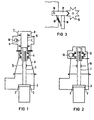
- FIG 1
- zeigt eine bisher bekannte zweiteilige Absperrarmatur.
- FIG 2
- zeigt eine Absperrarmatur nach der Erfindung, durch die Antriebsvorrichtung und Absperrvorrichtung zu einem System vereinigt sind.
- FIG 3
- zeigt als Teil einer erfindungsgemäßen Absperrarmatur eine Bremse.
- FIG. 1
- shows a previously known two-part shut-off valve.
- FIG 2
- shows a shut-off valve according to the invention, are combined by the drive device and shut-off device to form a system.
- FIG 3
- shows a brake as part of a shut-off valve according to the invention.
Eine Absperrarmatur nach den FIG 1 und 2 weist eine Spindel 1 auf, an die ein auf einen Sitz 2 aufsetzbarer Armaturenteller 3 angeformt ist. Mit der Spindel 1 steht eine Spindelmutter 4,12 in Eingriff, mit der eine Antriebsvorrichtung verbunden ist.A shut-off valve according to FIGS. 1 and 2 has a spindle 1, to which a
Bei einer bisher bekannten Absperrarmatur nach FIG 1 bildet eine Absperrvorrichtung 5, bestehend aus der Spindel 1 mit dem Armaturenteller 3 und der Spindelmutter 4 sowie einem Gehäuse 6 ein separates Bauteil. Auf die Absperrvorrichtung 5 ist eine gleichfalls separate Antriebsvorrichtung 7 aufgesetzt. Diese enthält in einem Gehäuse 8 eine Antriebsbuchse 9, die mit der Spindelmutter 4 koppelbar ist. Ein nicht dargestellter Elektromotor ist über eine Schnecke 10 und ein Schneckenrad 11 mit der Antriebsbuchse 9 verbunden. Die Antriebsvorrichtung 7 kann von der Absperrvorrichtung 5 abgenommen werden.In a previously known shut-off valve according to FIG. 1, a shut-off
Bei der erfindungsgemäßen Absperrarmatur nach FIG 2 steht eine als Schneckenrad ausgebildete Spindelmutter 12 mit der Spindel 1 in Eingriff. Ein nicht dargestellter Elektromotor ist über eine Schnecke 13 gleich mit der Spindelmutter 12 verbunden. In der erfindungsgemäßen Absperrarmatur wird die Spindel 1 ohne Zwischenschaltung einer Antriebsbuchse angetrieben. Die Antriebsvorrichtung ist in die Absperrvorrichtung integriert. Beide befinden sich untrennbar in nur einem Gehäuse 14.In the shut-off valve according to FIG. 2, a
Eine Bremse für die Spindel 1 besteht nach FIG 3 aus einem mit der Spindelmutter 12 verbundenen Zahnrad 15. Zwischen Zähne des Zahnrades 15 eingreifend ist um einen Stift 16 drehbar eine Klinke 17 angeordnet. Ein fest installierter Block 18 verhindert eine Auslenkung der Klinke 17 in einer bestimmten Drehrichtung und damit auch eine Drehung des Zahnrad es 15 in einer bestimmten Drehrichtung.According to FIG. 3, a brake for the spindle 1 consists of a
Entgegengesetzt ist hingegen eine Auslenkung der Klinke 17 gegen eine durch eine Feder 19 bewirkte Rückstellkraft und damit eine Drehung des Zahnrades 15 stets möglich.In contrast, a deflection of the
Claims (8)
- A shut-off valve having an operating arrangement and a valve rod (1) provided with a thread, on which valve rod a valve disc (3) mountable upon a seat (2) is pre-formed, with a valve rod nut (4, 12) being engaged with the valve rod (1) and the operating arrangement being arranged so as to communicate directly with the valve rod nut (12), characterised in that the thread of the valve rod (1) has a coarse pitch such that there is no self-locking and in that a brake is provided on the operating arrangement, which brake prevents self-movement of the valve rod (1) in a predetermined direction of rotation on account of the lack of self-locking, but permits movements in the opposite direction of rotation.
- A shut-off valve according to claim 1, characterised in that the thread of the valve rod (1) has a coarse pitch which is greater than 5°.
- A shut-off valve according to claim 1 or 2, characterised in that the brake comprises a toothed wheel (15) communicating with the valve rod nut (4, 12), and a pawl (17) arranged engaging between teeth of the toothed wheel (15), with it being possible for this pawl (17) to be deflected by the toothed wheel (15) against a restoring force in just one predetermined direction of rotation.
- A shut-off valve according to claim 3, characterised in that the pawl (17) can be deflected only when a predetermined force on the pawl (17) is exceeded.
- A shut-off valve according to one of claims 1 to 4, characterised in that the thread of the valve rod (1) is multi-threaded.
- A shut-off valve according to one of claims 1 to 5, characterised in that the valve rod (1) is formed from two parts and in that the two parts are rigidly coupled.
- A shut-off valve according to one of claims 1 to 6, characterised in that the operating arrangement has an electric motor which communicates directly with the valve rod nut (12) by way of a gear unit, with the gear unit being a worm gear unit (13) or a spur wheel gear unit or a planetary gear unit.
- A shut-off valve according to claim 7, characterised in that the electric motor can be controlled by a timing element.
Priority Applications (1)
| Application Number | Priority Date | Filing Date | Title |
|---|---|---|---|
| AT88110035T ATE96516T1 (en) | 1987-08-10 | 1988-06-23 | SHUT-OFF VALVE. |
Applications Claiming Priority (2)
| Application Number | Priority Date | Filing Date | Title |
|---|---|---|---|
| DE3726581 | 1987-08-10 | ||
| DE3726581 | 1987-08-10 |
Publications (3)
| Publication Number | Publication Date |
|---|---|
| EP0303801A1 EP0303801A1 (en) | 1989-02-22 |
| EP0303801B1 EP0303801B1 (en) | 1993-10-27 |
| EP0303801B2 true EP0303801B2 (en) | 1997-02-12 |
Family
ID=6333449
Family Applications (1)
| Application Number | Title | Priority Date | Filing Date |
|---|---|---|---|
| EP88110035A Expired - Lifetime EP0303801B2 (en) | 1987-08-10 | 1988-06-23 | Valve |
Country Status (4)
| Country | Link |
|---|---|
| EP (1) | EP0303801B2 (en) |
| AT (1) | ATE96516T1 (en) |
| DE (1) | DE3885196D1 (en) |
| ES (1) | ES2043734T5 (en) |
Cited By (3)
| Publication number | Priority date | Publication date | Assignee | Title |
|---|---|---|---|---|
| US8106538B2 (en) | 2001-09-19 | 2012-01-31 | Cameron International Corporation | DC voltage converting device |
| US8212378B2 (en) | 2000-10-30 | 2012-07-03 | Cameron International Corporation | Control and supply system |
| US8212410B2 (en) | 2002-11-12 | 2012-07-03 | Cameron International Corporation | Electric control and supply system |
Families Citing this family (8)
| Publication number | Priority date | Publication date | Assignee | Title |
|---|---|---|---|---|
| DE19650947C2 (en) * | 1996-12-07 | 1999-11-04 | Hartmann & Braun Gmbh & Co Kg | Axial clutch for an actuator |
| DE20018563U1 (en) | 2000-10-30 | 2002-03-21 | Cameron Gmbh | Actuating device, in particular for a throttle device |
| DE20115473U1 (en) | 2001-09-19 | 2003-02-20 | Biester Klaus | Universal energy supply system |
| DE20115474U1 (en) | 2001-09-19 | 2003-02-20 | Biester Klaus | DC converter device |
| DE20115471U1 (en) | 2001-09-19 | 2003-02-20 | Biester Klaus | Universal energy supply system |
| DE20115475U1 (en) | 2001-09-19 | 2003-02-20 | Biester Klaus | DC converter device |
| CN105240589B (en) * | 2015-11-02 | 2018-09-04 | 新疆水利水电科学研究院 | The column type control device of motor-driven valve low-power consumption valve |
| CN107283278A (en) * | 2017-07-29 | 2017-10-24 | 刘路清 | It is a kind of to clean the self-locking abrasive brush roll drive device derusted for steel plate |
Family Cites Families (6)
| Publication number | Priority date | Publication date | Assignee | Title |
|---|---|---|---|---|
| BE553737A (en) * | 1955-03-25 | |||
| US2948839A (en) * | 1956-04-09 | 1960-08-09 | Conval Corp | Motor control for positioning device |
| CH383717A (en) * | 1959-05-02 | 1964-10-31 | Int Bremsengesellschaft Mbh | Adjustment device with conversion of a rotary movement into a linear movement |
| DE1167431B (en) * | 1960-07-26 | 1964-04-09 | Fostoria Corp | Motor-driven device for actuating a valve stem |
| DE1185031B (en) * | 1962-06-27 | 1965-01-07 | Zikesch Carl Herbert | Drive for valves, which are housed in larger numbers in a longer high-pressure line |
| DE2141519A1 (en) * | 1971-08-19 | 1973-02-22 | Kloeckner Humboldt Deutz Ag | MOTOR DRIVE FOR CONTROL ELEMENTS |
-
1988
- 1988-06-23 EP EP88110035A patent/EP0303801B2/en not_active Expired - Lifetime
- 1988-06-23 ES ES88110035T patent/ES2043734T5/en not_active Expired - Lifetime
- 1988-06-23 DE DE88110035T patent/DE3885196D1/en not_active Expired - Fee Related
- 1988-06-23 AT AT88110035T patent/ATE96516T1/en not_active IP Right Cessation
Cited By (4)
| Publication number | Priority date | Publication date | Assignee | Title |
|---|---|---|---|---|
| US8212378B2 (en) | 2000-10-30 | 2012-07-03 | Cameron International Corporation | Control and supply system |
| US8536731B2 (en) | 2001-05-07 | 2013-09-17 | Cameron International Corporation | Electric control and supply system |
| US8106538B2 (en) | 2001-09-19 | 2012-01-31 | Cameron International Corporation | DC voltage converting device |
| US8212410B2 (en) | 2002-11-12 | 2012-07-03 | Cameron International Corporation | Electric control and supply system |
Also Published As
| Publication number | Publication date |
|---|---|
| ATE96516T1 (en) | 1993-11-15 |
| ES2043734T3 (en) | 1994-01-01 |
| EP0303801A1 (en) | 1989-02-22 |
| DE3885196D1 (en) | 1993-12-02 |
| ES2043734T5 (en) | 1997-04-01 |
| EP0303801B1 (en) | 1993-10-27 |
Similar Documents
| Publication | Publication Date | Title |
|---|---|---|
| EP0303801B2 (en) | Valve | |
| EP1404956B1 (en) | Electromotive drive comprising a worm | |
| EP0410487B1 (en) | Emergency drive for an electricly powered regulator | |
| EP1233690A1 (en) | Electromotive actuator | |
| EP3608557B1 (en) | Ball screw | |
| DE60025230T2 (en) | ELECTRIC BRAKE CONTROL MODULE FOR PLANES | |
| DE2134027A1 (en) | DRIVE DEVICE FOR MOVING WINDOWS, SUNROOFS AND THE LIKE OF MOTOR VEHICLES | |
| DE102008049251B4 (en) | Adjusting device for converting a rotary movement into a linear movement | |
| EP0599083A2 (en) | Drive assembly for controlling or regulating valves or the like | |
| DE2629112C3 (en) | PROTECTIVE MECHANISM TO PREVENT THE TRANSMISSION OF AN INADMISSIBLE TORQUE, IN PARTICULAR VALVE PROTECTIVE MECHANISM FOR VALVES | |
| DE3114708A1 (en) | VALVE ACTUATOR | |
| EP2933414A1 (en) | Door drive | |
| EP1111227B1 (en) | Exhaust gas recirculation valve | |
| EP3841316A1 (en) | Steer-by-wire steering gear having a hollow shaft motor and a ball screw drive | |
| DE102004003665B4 (en) | locking device | |
| DE10135141A1 (en) | starter | |
| EP0647542A1 (en) | Positioning drive with an electric drive motor, followed by a gearbox | |
| DE19519310A1 (en) | Differential gear for braking system actuator | |
| EP1093214A2 (en) | Linear drive | |
| DE2700928A1 (en) | ACTUATOR FOR AIR AND THROTTLE VALVES, MIXING TAPS AND THE LIKE. IN HEATING AND VENTILATION SYSTEMS | |
| DE4447395A1 (en) | Servo-drive with two brake motors for controlling valves, stop gates etc | |
| EP0305762A1 (en) | Electric-motor driven valve positioner with a time-dependent end of travel shut-off for fluid flow control systems | |
| DE3801904A1 (en) | Screw mechanism | |
| DE102007007885A1 (en) | Constant tension creator for ball-in-thread spindle transmission has second nut turned against first nut, and constant torque created by torque setting member | |
| DE19803541B4 (en) | Actuating device for the automated actuation of a rotationally and translationally movable switching element of a manual transmission |
Legal Events
| Date | Code | Title | Description |
|---|---|---|---|
| PUAI | Public reference made under article 153(3) epc to a published international application that has entered the european phase |
Free format text: ORIGINAL CODE: 0009012 |
|
| AK | Designated contracting states |
Kind code of ref document: A1 Designated state(s): AT BE CH DE ES FR GB GR IT LI LU NL SE |
|
| 17P | Request for examination filed |
Effective date: 19890726 |
|
| 17Q | First examination report despatched |
Effective date: 19900508 |
|
| RIN1 | Information on inventor provided before grant (corrected) |
Inventor name: ZILL, HEINRICH Inventor name: HOLTFOTH, PETER |
|
| GRAA | (expected) grant |
Free format text: ORIGINAL CODE: 0009210 |
|
| AK | Designated contracting states |
Kind code of ref document: B1 Designated state(s): AT BE CH DE ES FR GB GR IT LI LU NL SE |
|
| PG25 | Lapsed in a contracting state [announced via postgrant information from national office to epo] |
Ref country code: IT Free format text: LAPSE BECAUSE OF FAILURE TO SUBMIT A TRANSLATION OF THE DESCRIPTION OR TO PAY THE FEE WITHIN THE PRE;WARNING: LAPSES OF ITALIAN PATENTS WITH EFFECTIVE DATE BEFORE 2007 MAY HAVE OCCURRED AT ANY TIME BEFORE 2007. THE CORRECT EFFECTIVE DATE MAY BE DIFFERENT FROM THE ONE RECORDED.SCRIBED TIME-LIMIT Effective date: 19931027 Ref country code: GR Free format text: LAPSE BECAUSE OF FAILURE TO SUBMIT A TRANSLATION OF THE DESCRIPTION OR TO PAY THE FEE WITHIN THE PRESCRIBED TIME-LIMIT Effective date: 19931027 Ref country code: SE Effective date: 19931027 |
|
| REF | Corresponds to: |
Ref document number: 96516 Country of ref document: AT Date of ref document: 19931115 Kind code of ref document: T |
|
| REF | Corresponds to: |
Ref document number: 3885196 Country of ref document: DE Date of ref document: 19931202 |
|
| REG | Reference to a national code |
Ref country code: ES Ref legal event code: FG2A Ref document number: 2043734 Country of ref document: ES Kind code of ref document: T3 |
|
| GBT | Gb: translation of ep patent filed (gb section 77(6)(a)/1977) |
Effective date: 19931125 |
|
| ET | Fr: translation filed | ||
| PG25 | Lapsed in a contracting state [announced via postgrant information from national office to epo] |
Ref country code: LU Free format text: LAPSE BECAUSE OF NON-PAYMENT OF DUE FEES Effective date: 19940630 |
|
| PLBI | Opposition filed |
Free format text: ORIGINAL CODE: 0009260 |
|
| 26 | Opposition filed |
Opponent name: MANNESMANN AG Effective date: 19940727 |
|
| NLR1 | Nl: opposition has been filed with the epo |
Opponent name: MANNESMANN AG |
|
| PLAW | Interlocutory decision in opposition |
Free format text: ORIGINAL CODE: EPIDOS IDOP |
|
| PLAW | Interlocutory decision in opposition |
Free format text: ORIGINAL CODE: EPIDOS IDOP |
|
| PUAH | Patent maintained in amended form |
Free format text: ORIGINAL CODE: 0009272 |
|
| STAA | Information on the status of an ep patent application or granted ep patent |
Free format text: STATUS: PATENT MAINTAINED AS AMENDED |
|
| 27A | Patent maintained in amended form |
Effective date: 19970212 |
|
| AK | Designated contracting states |
Kind code of ref document: B2 Designated state(s): AT BE CH DE ES FR GB GR IT LI LU NL SE |
|
| REG | Reference to a national code |
Ref country code: CH Ref legal event code: AEN Free format text: AUFRECHTERHALTUNG DES PATENTES IN GEAENDERTER FORM |
|
| NLR2 | Nl: decision of opposition | ||
| REG | Reference to a national code |
Ref country code: ES Ref legal event code: DC2A Kind code of ref document: T5 Effective date: 19970218 |
|
| ET3 | Fr: translation filed ** decision concerning opposition | ||
| NLR3 | Nl: receipt of modified translations in the netherlands language after an opposition procedure | ||
| GBTA | Gb: translation of amended ep patent filed (gb section 77(6)(b)/1977) | ||
| PGFP | Annual fee paid to national office [announced via postgrant information from national office to epo] |
Ref country code: AT Payment date: 19970602 Year of fee payment: 10 |
|
| PGFP | Annual fee paid to national office [announced via postgrant information from national office to epo] |
Ref country code: BE Payment date: 19970609 Year of fee payment: 10 |
|
| PGFP | Annual fee paid to national office [announced via postgrant information from national office to epo] |
Ref country code: ES Payment date: 19970611 Year of fee payment: 10 |
|
| PGFP | Annual fee paid to national office [announced via postgrant information from national office to epo] |
Ref country code: NL Payment date: 19970619 Year of fee payment: 10 |
|
| PG25 | Lapsed in a contracting state [announced via postgrant information from national office to epo] |
Ref country code: AT Free format text: LAPSE BECAUSE OF NON-PAYMENT OF DUE FEES Effective date: 19980623 |
|
| PG25 | Lapsed in a contracting state [announced via postgrant information from national office to epo] |
Ref country code: BE Free format text: LAPSE BECAUSE OF NON-PAYMENT OF DUE FEES Effective date: 19980630 |
|
| BERE | Be: lapsed |
Owner name: SIEMENS A.G. Effective date: 19980630 |
|
| PG25 | Lapsed in a contracting state [announced via postgrant information from national office to epo] |
Ref country code: NL Free format text: LAPSE BECAUSE OF NON-PAYMENT OF DUE FEES Effective date: 19990101 |
|
| NLV4 | Nl: lapsed or anulled due to non-payment of the annual fee |
Effective date: 19990101 |
|
| PGFP | Annual fee paid to national office [announced via postgrant information from national office to epo] |
Ref country code: GB Payment date: 19990616 Year of fee payment: 12 |
|
| PG25 | Lapsed in a contracting state [announced via postgrant information from national office to epo] |
Ref country code: ES Free format text: LAPSE BECAUSE OF NON-PAYMENT OF DUE FEES Effective date: 19990624 |
|
| PGFP | Annual fee paid to national office [announced via postgrant information from national office to epo] |
Ref country code: FR Payment date: 19990629 Year of fee payment: 12 |
|
| PGFP | Annual fee paid to national office [announced via postgrant information from national office to epo] |
Ref country code: DE Payment date: 19990820 Year of fee payment: 12 |
|
| PGFP | Annual fee paid to national office [announced via postgrant information from national office to epo] |
Ref country code: CH Payment date: 19990920 Year of fee payment: 12 |
|
| PG25 | Lapsed in a contracting state [announced via postgrant information from national office to epo] |
Ref country code: GB Free format text: LAPSE BECAUSE OF NON-PAYMENT OF DUE FEES Effective date: 20000623 |
|
| PG25 | Lapsed in a contracting state [announced via postgrant information from national office to epo] |
Ref country code: LI Free format text: LAPSE BECAUSE OF NON-PAYMENT OF DUE FEES Effective date: 20000630 Ref country code: CH Free format text: LAPSE BECAUSE OF NON-PAYMENT OF DUE FEES Effective date: 20000630 |
|
| GBPC | Gb: european patent ceased through non-payment of renewal fee |
Effective date: 20000623 |
|
| REG | Reference to a national code |
Ref country code: CH Ref legal event code: PL |
|
| PG25 | Lapsed in a contracting state [announced via postgrant information from national office to epo] |
Ref country code: FR Free format text: LAPSE BECAUSE OF NON-PAYMENT OF DUE FEES Effective date: 20010228 |
|
| REG | Reference to a national code |
Ref country code: FR Ref legal event code: ST |
|
| PG25 | Lapsed in a contracting state [announced via postgrant information from national office to epo] |
Ref country code: DE Free format text: LAPSE BECAUSE OF NON-PAYMENT OF DUE FEES Effective date: 20010403 |
|
| REG | Reference to a national code |
Ref country code: ES Ref legal event code: FD2A Effective date: 20010503 |