EP0303775B1 - Method for making a tunnel by using a driving shield - Google Patents
Method for making a tunnel by using a driving shield Download PDFInfo
- Publication number
- EP0303775B1 EP0303775B1 EP88108029A EP88108029A EP0303775B1 EP 0303775 B1 EP0303775 B1 EP 0303775B1 EP 88108029 A EP88108029 A EP 88108029A EP 88108029 A EP88108029 A EP 88108029A EP 0303775 B1 EP0303775 B1 EP 0303775B1
- Authority
- EP
- European Patent Office
- Prior art keywords
- gap
- sealing ring
- shield
- extruded concrete
- tubbing
- Prior art date
- Legal status (The legal status is an assumption and is not a legal conclusion. Google has not performed a legal analysis and makes no representation as to the accuracy of the status listed.)
- Expired - Lifetime
Links
Images
Classifications
-
- E—FIXED CONSTRUCTIONS
- E21—EARTH DRILLING; MINING
- E21D—SHAFTS; TUNNELS; GALLERIES; LARGE UNDERGROUND CHAMBERS
- E21D9/00—Tunnels or galleries, with or without linings; Methods or apparatus for making thereof; Layout of tunnels or galleries
- E21D9/06—Making by using a driving shield, i.e. advanced by pushing means bearing against the already placed lining
- E21D9/0635—Tail sealing means, e.g. used as end shuttering
Definitions
- the invention relates generically to a method for shield tunneling with a shield tunneling machine, which has a working chamber under atmospheric pressure, and with a segment lining from composite segment segments, the face being supported with the help of a pressure medium, which via the control gap of the shield with the mountain-side gap between the shield tail and the segment lining is connected, the gap towards the working chamber is closed off by a gap sealing ring and grouted concrete is pressed into the gap space by pipe sockets in the gap sealing ring. So you work especially in loose floors.
- the pressure medium is a fluid medium, mostly air.
- the gap between the shield tail and the segment lining is not filled with grout concrete over the entire gap width. Rather, a pasty layer, for example in the form of a bentonite suspension, is first applied to the rock in the direction of advance. Then the space between the pasty layer and the shield tail is filled with grouted concrete.
- the one applied to the mountains pasty layer is intended to prevent compressed air from escaping through the control gap and the gap space into the working chamber which is under atmospheric pressure.
- Concrete usually has aggregates with coarse and fine fractions (FR-A 451 532, FR-A 25 15 092). In practice, the grain gradation is chosen so that a grain structure that is as densely packed as possible with the smallest possible surface can be achieved in concrete. Standard sieve lines for the concrete aggregates are known (Ullmann, Volume 8, page 316).
- leakage joints between the gap sealing ring and the segmental lining cannot always be excluded, because the individual segmental segments can be slightly offset from one another in the radial direction. Sometimes leakage gaps of up to 15 mm remain. Through such an impermeability joint, the liquid grouting concrete flows into the inside of the shield without the intended pressure in the grouting concrete being able to be maintained to support the surrounding soil. The risk of runoff is greater, the higher the grouting pressures that are required for lower-lying tunnels. As part of the known measures, it is not possible to ensure that the compression pressure for the grouted concrete is always reliably greater than the pressure that arises from the load.
- the pressure medium in particular a gaseous pressure medium, can flow through an imperfectly filled gap space, which has flowed through the control gap surrounding the shield to behind the shield tail. If the gap sealing ring does not seal, the pressure medium escapes into the working chamber.
- Compressed air support for the working face is more advantageous than supporting the working face with liquid, because the excavated soil can be removed dry.
- the entire tunnel tube has previously been placed under compressed air to support the ground on the face.
- Attempts to place only one working chamber in the front area of the shield under compressed air, in order to thereby enable the tunneling teams to work under atmospheric pressure, have become known, but failed due to the problems explained above.
- Pressure medium losses and especially compressed air losses occur when the pressure medium flows backwards in the control gap on the outside of the shield and penetrates into the working chamber through an imperfect seal of the gap sealing ring.
- the invention has for its object to carry out the method described above so that in the gap space for the support of the soil is ensured by sufficient grouting pressure of the flowable grouting concrete, even if there are leakage joints between the gap sealing ring and the segmental lining which result from an offset of neighboring segmental segments.
- the method should also be able to be carried out in a simple manner.
- the invention teaches that a gap sealing ring is used, which extends from the segment lining to the shield tail and is elastically supported in the direction of advance, and that the grouting concrete introduced into the gap space has coarse-grained aggregates with a maximum grain size of not less than 4 mm contains and that the grouting concrete fine particles, the flour grain content additives are added in such an amount that the pores of a coarse-grained aggregates formed hydrodynamically formed grain filter in front of up to 15 mm large leakage joints between the gap sealing ring and the segmental lining, thereby sealing the leakage joints will.
- the sealing achieved by the formation of the grain filter is surprisingly effective even because the grouting concrete is pressed into the gap space under a pressure of up to 10 bar.
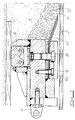
- the gap sealing ring shown in the figures is arranged between the rear end of a shield tail 1 and the front end of a segment lining 2 and serves to seal the gap space 3 in the course of its compression with grouting concrete.
- the gap sealing ring is freely movable relative to the shield tail 1 and tubbing extension 2 via adjustable support units in the form of cylinder piston arrangements in the direction of advance, for example on the shield. These support units are not shown in detail in the figures; 1 shows only one of a plurality of fastening eyes 4 to which the supporting units are fastened.
- a number of grout supply pipe sockets 5 are provided (cf. FIG. 2).
- the gap seal ring has an elastic outer seal 6 and an elastic inner seal 7.
- the elastic outer seal 6 consists of a rubber or plastic ring which can be placed on the inside of the tail 1; radial adjustment screws 8 are provided accordingly for this purpose.
- the inner seal 7 which can be pressed against the outside of the segment lining 2 consists of a trailing spring plate seal which is fastened to the gap sealing ring by radial screws 9.
- Fig. 1 shows that a grain filter 11 has built up from the coarse-grained aggregates of the grouted concrete in front of the leakage joint 10, and that the pores of the grain filter have been closed by the fine additives 12. Some of them have passed the grain filter and also closed the leakage joint 10.
- the proportion of fine additives, in particular that of the flour grain content, is increased compared to a conventional grouting concrete.
- a preferred embodiment of the invention is characterized in that amorphous silica in the form of precipitated silica or silica produced by high-temperature hydrolysis is added to the grouting concrete.
- amorphous silica In general, 2 to 4% by weight of amorphous silica, based on the cement weight, is sufficient.
- the seal can also be improved by coordinating the other additives, such as flow agents, retarders and stabilizers.
- An addition of bentonite is also within the scope of the invention, for example in an amount of 2 to 6% by weight, preferably 4% by weight, based on the cement weight.
Description
Die Erfindung bezieht sich gattungsgemäß auf ein Verfahren zum Schildvortrieb eines Tunnels mit einer Schildvortriebsmaschine, die eine unter atmosphärischem Druck stehende Arbeitskammer aufweist, und mit einem Tübbingausbau aus zusammengesetzten Tübbingsegmenten, wobei die Ortsbrust mit Hilfe eines Druckmittels gestützt wird, welches über den Steuerspalt des Schildes mit dem gebirgeseitigen Spaltraum zwischen Schildschwanz und dem Tübbingausbau in Verbindung steht, wobei der Spaltraum zur Arbeitskammer hin durch einen Spaltdichtungsring abgeschlossen ist und durch Rohrstutzen im Spaltdichtungsring Verpreßbeton in den Spaltraum eingepreßt wird. So arbreitet man insbesondere in Lockerböden. Das Druckmittel ist ein fluides Medium, zumeist Luft.The invention relates generically to a method for shield tunneling with a shield tunneling machine, which has a working chamber under atmospheric pressure, and with a segment lining from composite segment segments, the face being supported with the help of a pressure medium, which via the control gap of the shield with the mountain-side gap between the shield tail and the segment lining is connected, the gap towards the working chamber is closed off by a gap sealing ring and grouted concrete is pressed into the gap space by pipe sockets in the gap sealing ring. So you work especially in loose floors. The pressure medium is a fluid medium, mostly air.
Bei dem aus der FR-A-2.560.635 bekannten gattungsgemäßen Verfahren wird der Spaltraum zwischen dem Schildschwanz und dem Tübbingausbau nicht über die gesamte Spaltbreite mit Verpreßbeton ausgefüllt. In Vortriebsrichtung wird vielmehr zunächst eine pastöse Schicht, zum Beispiel in Form einer Bentonit-Suspension, auf das Gebirge aufgetragen. Anschließend wird der Zwischenraum zwischen der pastösen Schicht und dem Schildschwanz mit Verpreßbeton verfüllt. Die auf das Gebirge aufgetragene pastöse Schicht soll ein Entweichen von Druckluft über den Steuerspalt und den Spaltraum in die unter atmosphärischem Druck stehende Arbeitskammer verhindern. Beton weist üblicherweise Zuschläge mit Grob- und Feinanteilen auf (FR-A 451 532, FR-A 25 15 092). Die Kornabstufung wird in der Praxis so gewählt, daß in Beton ein möglichst dichtgepacktes Korngefüge mit möglichst geringer Oberfläche erreicht werden kann. Regelsieblinien für die Betonzuschläge sind bekannt (Ullmann, Band 8, Seite 316).In the generic method known from FR-A-2.560.635, the gap between the shield tail and the segment lining is not filled with grout concrete over the entire gap width. Rather, a pasty layer, for example in the form of a bentonite suspension, is first applied to the rock in the direction of advance. Then the space between the pasty layer and the shield tail is filled with grouted concrete. The one applied to the mountains pasty layer is intended to prevent compressed air from escaping through the control gap and the gap space into the working chamber which is under atmospheric pressure. Concrete usually has aggregates with coarse and fine fractions (FR-A 451 532, FR-A 25 15 092). In practice, the grain gradation is chosen so that a grain structure that is as densely packed as possible with the smallest possible surface can be achieved in concrete. Standard sieve lines for the concrete aggregates are known (Ullmann,
Aus der DE-A 26 23 223 ist ein Verfahren zum Schildvortrieb eines Tunnels bekannt, das mit einer in Form einer Ringbürste gestalteten Spaltdichtung arbeitet. Der Spaltraum wird mit Zementmörtel verfüllt. Das Verpressen des Spaltraumes mit Zementmörtel und gleichartigen feinkörnigen Gemischen entspricht auch dem aus der Praxis bekannten Stand der Technik.From DE-A 26 23 223 a method for shield driving a tunnel is known which works with a gap seal designed in the form of an annular brush. The gap is filled with cement mortar. The grouting of the gap with cement mortar and similar fine-grained mixtures also corresponds to the prior art known from practice.
Arbeitet man nach dem gattungsgemäßen Verfahren, so können Undichtigkeitsfugen zwischen dem Spaltdichtungsring und dem Tübbingausbau nicht immer ausgeschlossen werden, weil die einzelnen Tübbingsegmente gegeneinander in radialer Richtung ein wenig versetzt sein können. Zuweilen bleiben Undichtigkeitsfugen von bis zu 15 mm. Durch eine solche Udichtigkeitsfuge fließt der flüssige Verpreßbeton ins Schildinnere ab, ohne daß der vorgesehene Druck im Verpreßbeton zur Stützung des umgebenden Bodens gehalten werden kann. Die Abfließgefahr ist um so größer, je höher die Verpreßdrücke sind, die man bei tieferliegenden Tunneln benötigt. Im Rahmen der bekannten Maßnahmen gelingt es nicht, sicherzustellen, daß der Verpreßdruck für den Verpreßbeton immer zuverlässig größer ist als derjenige Druck, der aus der Belastung entsteht. Insbesondere bei einem Tunnelvortrieb in Lockerböden oder in gebrächem Gestein besteht die Gefahr, daß bei reduziertem Verpreßdruck Boden in den Spaltraum fällt, wodurch es unmöglich wird, den Schildschwanzspalt vollkommen zu verfüllen. Durch einen nur unvollkommen verfüllten Spaltraum kann das Druckmittel, insbesondere ein gasförmiges Druckmittel, strömen, welches durch den den schildumgebenden Steuerspalt bis hinter den Schildschwanz geflossen ist. Wenn der Spaltdichtungsring nicht abdichtet, entweicht das Druckmittel in die Arbeitskammer.If one works according to the generic method, then leakage joints between the gap sealing ring and the segmental lining cannot always be excluded, because the individual segmental segments can be slightly offset from one another in the radial direction. Sometimes leakage gaps of up to 15 mm remain. Through such an impermeability joint, the liquid grouting concrete flows into the inside of the shield without the intended pressure in the grouting concrete being able to be maintained to support the surrounding soil. The risk of runoff is greater, the higher the grouting pressures that are required for lower-lying tunnels. As part of the known measures, it is not possible to ensure that the compression pressure for the grouted concrete is always reliably greater than the pressure that arises from the load. In particular, when tunneling in loose soil or in rock, there is a risk that soil will fall into the gap space with reduced compression pressure, which makes it impossible to completely fill the shield tail gap. The pressure medium, in particular a gaseous pressure medium, can flow through an imperfectly filled gap space, which has flowed through the control gap surrounding the shield to behind the shield tail. If the gap sealing ring does not seal, the pressure medium escapes into the working chamber.
Eine Druckluftstützung der Ortsbrust ist im Vergleich zu einer Stützung der Ortsbrust durch Flüssigkeit vorteilhafter, weil der abgebaute Boden trocken abtransportiert werden kann. In der Praxis wurde bisher die gesamte Tunnelröhre unter Druckluft gesetzt, um den Boden an der Ortsbrust zu stützen. Versuche, lediglich eine Arbeitskammer im vorderen Bereich des Schildes unter Druckluft zu setzen, um dadurch den Vortriebsmannschaften die Arbeit unter atmosphärischem Druck zu ermöglichen, sind zwar bekannt geworden, scheiterten jedoch an den vorstehend erläuterten Problemen. Druckmittelverluste und insbesondere Druckluftverluste treten auf, wenn das Druckmittel an der Außenseite des Schildes im Steuerspalt nach hinten fließt und durch eine unvollkommene Dichtung des Spaltdichtungsringes in die Arbeitskammer dringt.Compressed air support for the working face is more advantageous than supporting the working face with liquid, because the excavated soil can be removed dry. In practice, the entire tunnel tube has previously been placed under compressed air to support the ground on the face. Attempts to place only one working chamber in the front area of the shield under compressed air, in order to thereby enable the tunneling teams to work under atmospheric pressure, have become known, but failed due to the problems explained above. Pressure medium losses and especially compressed air losses occur when the pressure medium flows backwards in the control gap on the outside of the shield and penetrates into the working chamber through an imperfect seal of the gap sealing ring.
Der Erfindung liegt die Aufgabe zugrunde, das eingangs beschriebene Verfahren so zu führen, daß im Spaltraum ein für die Stützung des Bodens ausreichender Verpreßdruck des fließfähigen Verpreßbetons sichergestellt ist, und zwar auch dann, wenn Undichtigkeitsfugen zwischen dem Spaltdichtungsring und dem Tübbingausbau vorhanden sind, die aus einem Versatz von benachbarten Tübbingsegmenten resultieren. Dabei soll das Verfahren auch auf einfache weise ausführbar sein.The invention has for its object to carry out the method described above so that in the gap space for the support of the soil is ensured by sufficient grouting pressure of the flowable grouting concrete, even if there are leakage joints between the gap sealing ring and the segmental lining which result from an offset of neighboring segmental segments. The method should also be able to be carried out in a simple manner.
Zur Lösung dieser Aufgabe lehrt die Erfindung, daß mit einem Spaltdichtungsring gearbeitet wird, der sich von dem Tübbingausbau bis zu dem Schildschwanz erstreckt und in Vortriebsrichtung elastisch abgestützt ist, und daß der in den Spaltraum eingebrachte Verpreßbeton grobkörnige Zuschlagstoffe mit einem Größtkorn von nicht kleiner als 4 mm enthält und daß dem Verpreßbeton ferner feinteilige, den Mehlkorngehalt erhöhende Zusatzstoffe in einer Menge zugegeben werden, daß die Poren eines aus den grobkörnigen Zuschlagstoffen sich hydrodynamisch bildenden Kornfilters vor bis zu 15 mm großen Undichtigkeitsfugen zwischen dem Spaltdichtungsring und dem Tübbingausbau verschlossen und dadurch die Undichtigkeitsfugen abgedichtet werden. Die durch die Ausbildung des Kornfilters erreichte Abdichtung ist überraschenderweise selbst dann wirksam, denn der Verpreßbeton unter einem Druck von bis zu 10 bar in den Spaltraum eingedrückt wird.To achieve this object, the invention teaches that a gap sealing ring is used, which extends from the segment lining to the shield tail and is elastically supported in the direction of advance, and that the grouting concrete introduced into the gap space has coarse-grained aggregates with a maximum grain size of not less than 4 mm contains and that the grouting concrete fine particles, the flour grain content additives are added in such an amount that the pores of a coarse-grained aggregates formed hydrodynamically formed grain filter in front of up to 15 mm large leakage joints between the gap sealing ring and the segmental lining, thereby sealing the leakage joints will. The sealing achieved by the formation of the grain filter is surprisingly effective even because the grouting concrete is pressed into the gap space under a pressure of up to 10 bar.
Im folgenden werden die beschriebenen und weiteren Merkmale der Erfindung anhand einer lediglich ein Ausführungsbeispiel darstellenden Zeichnung ausführlicher erläutert. Es zeigen
- Fig. 1
- einen Schnitt durch einen Spaltdichtungsring beim Tunnelvortrieb nach dem erfindungsgemäßen Verfahren und
- Fig. 2
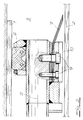
- einen Fig. 1 entsprechenden Schnitt durch den Spaltdichtungsring in einer anderen Winkelstellung.
- Fig. 1
- a section through a gap sealing ring during tunneling according to the inventive method and
- Fig. 2
- a section corresponding to Fig. 1 through the gap sealing ring in a different angular position.
Der in den Figuren dargestellte Spaltdichtungsring ist zwischen dem Hinterende eines Schildschwanzes 1 sowie dem Voderende eines Tübbingausbaus 2 angeordnet und dient zum Abdichten des Spaltraumes 3 im Zuge von dessen Verpressung mit Verpreßbeton. Der Spaltdichtungsring ist relativ zum Schildschwanz 1 und Tübbingausbau 2 frei beweglich über einstellbare Stützaggregate in Form von Zylinderkolbenanordnungen in Vortriebsrichtung federnd, beispielsweise am Schild, abgestützt. In den Figuren sind diese Stützaggregate im einzelnen nicht dargestellt; erkennbar ist in Fig. 1 nur eines von mehreren Befestigungsaugen 4, an denen die Stützaggregate befestigt sind. Gleichmäßig über den Umfang verteilt sind an der vorderen Stirnseite des Spaltdichtungsringes mehrere Verpreßmaterialzuführungsrohrstutzen 5 vorgesehen (vgl. Fig. 2). Außerdem weist der Spaltdichtungsring eine elastische Außendichtung 6 und eine elastische Innendichtung 7 auf. Die elastische Außendichtung 6 besteht aus einem Gummi- oder Kunststoffring, der an die Innenseite des Schildschwanzes 1 anlegbar ist; hierzu sind entsprechend radiale Einstellschrauben 8 vorgesehen. Die gegen die Außenseite des Tübbingausbaus 2 preßbare Innendichtung 7 besteht aus einer nachlaufenden Federblechabdichtung, die durch Radialschrauben 9 am Spaltdichtungsring befestigt ist.The gap sealing ring shown in the figures is arranged between the rear end of a shield tail 1 and the front end of a
In den Fig. 1 und 2 wurde angedeutet, daß sich durch Versatz von Segmenten im Tunnelausbau 2 in dem Bereich, in dem der Schnitt geführt wurde, eine Undichtigkeitsfuge 10 gebildet hat. Die Fig. 1 zeigt, daß sich vor der Undichtigkeitsfuge 10 ein Kornfilter 11 aus den grobkörnigen Zuschlagstoffen des Verpreßbetons aufgebaut hat, und daß die Poren des Kornfilters durch die feinen Zusatzstoffe 12 verschlossen wurden. Einige davon haben das Kornfilter passiert und auch die Undichtigkeitsfuge 10 geschlossen. Der Anteil an feinen Zusatzstoffen, insbesondere der des Mehlkorngehaltes, ist gegenüber einem üblichen Verpreßbeton erhöht. Eine bevorzugte Ausführungsform der Erfindung ist dadurch gekennzeichnet, daß dem Verpreßbeton amorphe Kieselsäure in Form von Fällungskieselsäure oder durch Hochtemperaturhydrolyse hergestellter Kieselsäure beigegeben wird. Im allgemeinen reichen 2 bis 4 Gew.-% an amorpher Kieselsaure, bezogen auf das Zementgewicht. Auch durch eine Abstimmung der übrigen Zusatzstoffe, wie Fließmittel, Verzögerer und Stabilisatoren, kann die Abdichtung verbessert werden. In Rahmen der Erfindung liegt auch eine Beigabe an Bentonit, beispielsweise in einer Menge von 2 bis 6 Gew.-%, vorzugsweise 4 Gew.-%, bezogen auf das Zementgewicht.1 and 2, it has been indicated that an
Claims (3)
- A process for driving a tunnel with a shield driving machine, that possesses an operating chamber subjected to atmospheric pressure, and with a tubbing support (2) of assembled tubbing segments,
in which the face surface is supported with the aid of a pressure medium that, through a steering gap of the shield, communicates with the rockface gap space (3) between the shield tail (1) and the tubbing support (2),
in which the gap space (3) is closed off from the operating chamber by a gap sealing ring (6, 7) and extruded concrete is forced into the gap space through tubular outlets (5) in the gap sealing ring,
characterized in
that a gap sealing ring (6, 7) is used that extends from the tubbing support (2) to the shield tail (1) and that is elastically supported in the driving direction,
that the extruded concrete introduced into the gap space contains coarse-grained additives with a grain size of not less than 4mm, and
that in addition fine-grained additives increasing the dust content are added to the extruded concrete in such quantity that the pores of a grain filter hydrodynamically formed from the coarse-grained additives are closed in advance of permeable gaps up to 15mm wide between the gap sealing ring (7) and the tubbing support (2), and thereby the permeable gaps are sealed off. - A process according to Claim 1, characterized in that amorphous silicic acid in the form of precipitated silicic acid or of silicic acid formed by hydrolysis at high temperatures is added to the extruded concrete.
- A process according to Claim 1 or 2, characterized in that bentonite in a quantity of 2 to 6% by weight relatively to the weight of cement is added to the extruded concrete.
Applications Claiming Priority (2)
| Application Number | Priority Date | Filing Date | Title |
|---|---|---|---|
| DE3726900 | 1987-08-13 | ||
| DE3726900 | 1987-08-13 |
Publications (2)
| Publication Number | Publication Date |
|---|---|
| EP0303775A1 EP0303775A1 (en) | 1989-02-22 |
| EP0303775B1 true EP0303775B1 (en) | 1992-03-04 |
Family
ID=6333615
Family Applications (1)
| Application Number | Title | Priority Date | Filing Date |
|---|---|---|---|
| EP88108029A Expired - Lifetime EP0303775B1 (en) | 1987-08-13 | 1988-05-19 | Method for making a tunnel by using a driving shield |
Country Status (4)
| Country | Link |
|---|---|
| US (1) | US4911578A (en) |
| EP (1) | EP0303775B1 (en) |
| JP (1) | JPH0723680B2 (en) |
| DK (1) | DK171200B1 (en) |
Families Citing this family (19)
| Publication number | Priority date | Publication date | Assignee | Title |
|---|---|---|---|---|
| DE19800963A1 (en) * | 1998-01-14 | 1999-07-22 | Holzmann Philipp Ag | Process for grouting the annular space between Tübbingen and the mountains |
| US6554368B2 (en) * | 2000-03-13 | 2003-04-29 | Oil Sands Underground Mining, Inc. | Method and system for mining hydrocarbon-containing materials |
| AU2003216047A1 (en) * | 2002-01-09 | 2003-07-30 | Oil Sands Underground Mining, Inc. | Method and means for processing oil sands while excavating |
| US7128375B2 (en) * | 2003-06-04 | 2006-10-31 | Oil Stands Underground Mining Corp. | Method and means for recovering hydrocarbons from oil sands by underground mining |
| US20070044957A1 (en) * | 2005-05-27 | 2007-03-01 | Oil Sands Underground Mining, Inc. | Method for underground recovery of hydrocarbons |
| US8287050B2 (en) * | 2005-07-18 | 2012-10-16 | Osum Oil Sands Corp. | Method of increasing reservoir permeability |
| CA2649850A1 (en) * | 2006-04-21 | 2007-11-01 | Osum Oil Sands Corp. | Method of drilling from a shaft for underground recovery of hydrocarbons |
| US20080078552A1 (en) * | 2006-09-29 | 2008-04-03 | Osum Oil Sands Corp. | Method of heating hydrocarbons |
| US7644769B2 (en) * | 2006-10-16 | 2010-01-12 | Osum Oil Sands Corp. | Method of collecting hydrocarbons using a barrier tunnel |
| CA2668774A1 (en) | 2006-11-22 | 2008-05-29 | Osum Oil Sands Corp. | Recovery of bitumen by hydraulic excavation |
| WO2009040683A2 (en) * | 2007-09-28 | 2009-04-02 | Osum Oil Sands Corp. | Method of upgrading bitumen and heavy oil |
| US8167960B2 (en) * | 2007-10-22 | 2012-05-01 | Osum Oil Sands Corp. | Method of removing carbon dioxide emissions from in-situ recovery of bitumen and heavy oil |
| US20090139716A1 (en) * | 2007-12-03 | 2009-06-04 | Osum Oil Sands Corp. | Method of recovering bitumen from a tunnel or shaft with heating elements and recovery wells |
| WO2009098597A2 (en) * | 2008-02-06 | 2009-08-13 | Osum Oil Sands Corp. | Method of controlling a recovery and upgrading operation in a reservor |
| CA2718885C (en) | 2008-05-20 | 2014-05-06 | Osum Oil Sands Corp. | Method of managing carbon reduction for hydrocarbon producers |
| CN103726857B (en) * | 2013-11-28 | 2017-01-04 | 江苏牧羊控股有限公司 | A kind of flexible die for shield segment |
| WO2020172195A1 (en) * | 2019-02-21 | 2020-08-27 | TopEng Inc. | System and method for simultaneous excavation and segment erection of tbm by thrust shell |
| CN110031369A (en) * | 2019-05-22 | 2019-07-19 | 中国水利水电第八工程局有限公司 | The underwater slurry shield mud film of bad ground forms simulator and analogy method |
| CN114017070B (en) * | 2021-12-08 | 2023-08-25 | 河北工程大学 | Visualization device capable of being used for simulating grouting particle accumulation effect of fractured rock mass |
Family Cites Families (14)
| Publication number | Priority date | Publication date | Assignee | Title |
|---|---|---|---|---|
| FR451532A (en) * | 1912-12-06 | 1913-04-21 | Eugene Louis Marie Martin | Waterproof concrete |
| US3672173A (en) * | 1969-05-13 | 1972-06-27 | Halliburton Co | Forming self-supporting barriers in mine passages and the like |
| US3774683A (en) * | 1972-05-23 | 1973-11-27 | Halliburton Co | Method for stabilizing bore holes |
| US3845632A (en) * | 1973-05-21 | 1974-11-05 | Mineral Ind | Method of sealing coal against methane emission |
| JPS5125534U (en) * | 1974-08-15 | 1976-02-25 | ||
| DE2623223C3 (en) * | 1975-05-30 | 1978-05-24 | Tekken Kensetu Co. Ltd., Tokio | Annular gap seal for tunneling |
| DE2555780C3 (en) * | 1975-12-11 | 1979-04-19 | Wayss & Freytag Ag, 6000 Frankfurt | Annular gap sealing for shield tunneling machines |
| DE3043312C2 (en) * | 1980-11-17 | 1986-10-09 | Heinz-Theo Dipl.-Ing. 5300 Bonn Walbröhl | Sliding formwork for inserting an in-situ concrete lining as well as a method for inserting in-situ concrete in gallery and tunnel construction |
| JPS6214237Y2 (en) * | 1981-02-02 | 1987-04-11 | ||
| FR2515092A1 (en) * | 1981-10-22 | 1983-04-29 | Comminges Betons | Inexpensive concrete for construction industry - where part of conventional cement is replaced by ultrafine silica flour, and very short mixing time is used |
| DE3407384A1 (en) * | 1983-09-07 | 1985-08-29 | Dyckerhoff & Widmann AG, 8000 München | Method of producing a tubular underground hollow space, e.g. a traffic tunnel, and apparatus for carrying out the method |
| FI69503C (en) * | 1984-03-13 | 1986-02-10 | Neste Oy | YTBELAGD BERGSBEHAOLLARE ELLER TUNNEL |
| DE3411857C1 (en) * | 1984-03-30 | 1985-04-18 | Hochtief Ag Vorm. Gebr. Helfmann, 4300 Essen | Between a shield jacket of a tunnel boring machine and a tunnel inner formwork, length-adjustable front circuit |
| US4789267A (en) * | 1985-03-13 | 1988-12-06 | Hochtief Aktiengesellschaft Vorm. Gebr. Helfmann | Method of and apparatus for concrete tunnel lining |
-
1988
- 1988-05-19 EP EP88108029A patent/EP0303775B1/en not_active Expired - Lifetime
- 1988-05-24 DK DK282888A patent/DK171200B1/en not_active IP Right Cessation
- 1988-06-20 JP JP63150400A patent/JPH0723680B2/en not_active Expired - Lifetime
- 1988-08-15 US US07/232,606 patent/US4911578A/en not_active Expired - Fee Related
Also Published As
| Publication number | Publication date |
|---|---|
| DK282888A (en) | 1989-02-14 |
| JPH01142196A (en) | 1989-06-05 |
| DK171200B1 (en) | 1996-07-22 |
| US4911578A (en) | 1990-03-27 |
| DK282888D0 (en) | 1988-05-24 |
| JPH0723680B2 (en) | 1995-03-15 |
| EP0303775A1 (en) | 1989-02-22 |
Similar Documents
| Publication | Publication Date | Title |
|---|---|---|
| EP0303775B1 (en) | Method for making a tunnel by using a driving shield | |
| DE2103760A1 (en) | Tunnel construction process | |
| DE2704438A1 (en) | METHOD OF REPAIRING DRAIN PIPE | |
| DE2108591A1 (en) | Device and procedure for the implementation of the shield construction method for the construction of tunnels or galleries | |
| DE2932430C2 (en) | Method for placing a concrete tunnel lining | |
| EP0288707B1 (en) | Earth pressure shield | |
| DE3827441C2 (en) | ||
| EP0205853B1 (en) | Method for producing a pipelike underground cavity, e.g. a tunnel, gallery or the like, by means of shield driving, and device for carrying out the method | |
| DE1206938B (en) | Controllable propulsion shield for driving tunnels, routes or the like, and method for producing an in-situ concrete lining with such a propulsion shield | |
| DE1197914B (en) | Annular gap seal for jacking shields | |
| DE2505668A1 (en) | DEVICE ON DRILLING EQUIPMENT | |
| DE3407384A1 (en) | Method of producing a tubular underground hollow space, e.g. a traffic tunnel, and apparatus for carrying out the method | |
| DE3222556C1 (en) | Method and device for producing a tunnel in pressurized mountains by means of shield driving | |
| DE102007024057B4 (en) | Process for the consolidation and / or sealing of loose geological formations in the course of geotechnical construction measures | |
| DE3543059C2 (en) | ||
| DE2250635B2 (en) | Method of making a tunnel | |
| DE3545084A1 (en) | TUNNEL CONSTRUCTION | |
| DE3336153C2 (en) | Hollow body that can be filled with building material | |
| DE3242133A1 (en) | Support method and hollow bodies to be filled with construction material | |
| DE3642893C2 (en) | ||
| DE2454913C3 (en) | Method and arrangement for driving a tunnel | |
| DE4225121A1 (en) | Method of supporting tunnel face during shield driving excavation - involves bulkhead with high level shuttered opening and vertical partition next to face forming air pocket in between | |
| DE2744270C2 (en) | Telescopic pipe for filling concrete behind a shuttering of a route extension in mining and tunneling | |
| DE3633350C1 (en) | Method of supplying compressed air to the working chamber and the personnel and materials lock of a manhole cylinder and device for carrying out the method | |
| DE3126651C1 (en) | End formwork for a tunnel-driving machine |
Legal Events
| Date | Code | Title | Description |
|---|---|---|---|
| PUAI | Public reference made under article 153(3) epc to a published international application that has entered the european phase |
Free format text: ORIGINAL CODE: 0009012 |
|
| 17P | Request for examination filed |
Effective date: 19880616 |
|
| AK | Designated contracting states |
Kind code of ref document: A1 Designated state(s): BE FR GB IT NL |
|
| 17Q | First examination report despatched |
Effective date: 19900228 |
|
| GRAA | (expected) grant |
Free format text: ORIGINAL CODE: 0009210 |
|
| AK | Designated contracting states |
Kind code of ref document: B1 Designated state(s): BE FR GB IT NL |
|
| PG25 | Lapsed in a contracting state [announced via postgrant information from national office to epo] |
Ref country code: NL Effective date: 19920304 |
|
| ITF | It: translation for a ep patent filed |
Owner name: ING. A. GIAMBROCONO & C. S.R.L. |
|
| GBT | Gb: translation of ep patent filed (gb section 77(6)(a)/1977) | ||
| ET | Fr: translation filed | ||
| NLV1 | Nl: lapsed or annulled due to failure to fulfill the requirements of art. 29p and 29m of the patents act | ||
| PLBE | No opposition filed within time limit |
Free format text: ORIGINAL CODE: 0009261 |
|
| STAA | Information on the status of an ep patent application or granted ep patent |
Free format text: STATUS: NO OPPOSITION FILED WITHIN TIME LIMIT |
|
| 26N | No opposition filed | ||
| PGFP | Annual fee paid to national office [announced via postgrant information from national office to epo] |
Ref country code: GB Payment date: 19970423 Year of fee payment: 10 |
|
| PG25 | Lapsed in a contracting state [announced via postgrant information from national office to epo] |
Ref country code: GB Free format text: LAPSE BECAUSE OF NON-PAYMENT OF DUE FEES Effective date: 19980519 |
|
| GBPC | Gb: european patent ceased through non-payment of renewal fee |
Effective date: 19980519 |
|
| PGFP | Annual fee paid to national office [announced via postgrant information from national office to epo] |
Ref country code: BE Payment date: 20000327 Year of fee payment: 13 |
|
| PGFP | Annual fee paid to national office [announced via postgrant information from national office to epo] |
Ref country code: FR Payment date: 20000426 Year of fee payment: 13 |
|
| PG25 | Lapsed in a contracting state [announced via postgrant information from national office to epo] |
Ref country code: BE Free format text: LAPSE BECAUSE OF NON-PAYMENT OF DUE FEES Effective date: 20010531 |
|
| BERE | Be: lapsed |
Owner name: HOCHTIEF A.G. VORM. GEBR. HELFMANN Effective date: 20010531 |
|
| PG25 | Lapsed in a contracting state [announced via postgrant information from national office to epo] |
Ref country code: FR Free format text: LAPSE BECAUSE OF NON-PAYMENT OF DUE FEES Effective date: 20020131 |
|
| PG25 | Lapsed in a contracting state [announced via postgrant information from national office to epo] |
Ref country code: IT Free format text: LAPSE BECAUSE OF NON-PAYMENT OF DUE FEES;WARNING: LAPSES OF ITALIAN PATENTS WITH EFFECTIVE DATE BEFORE 2007 MAY HAVE OCCURRED AT ANY TIME BEFORE 2007. THE CORRECT EFFECTIVE DATE MAY BE DIFFERENT FROM THE ONE RECORDED. Effective date: 20050519 |