EP0298183B1 - Incremental position measuring system - Google Patents
Incremental position measuring system Download PDFInfo
- Publication number
- EP0298183B1 EP0298183B1 EP19870890154 EP87890154A EP0298183B1 EP 0298183 B1 EP0298183 B1 EP 0298183B1 EP 19870890154 EP19870890154 EP 19870890154 EP 87890154 A EP87890154 A EP 87890154A EP 0298183 B1 EP0298183 B1 EP 0298183B1
- Authority
- EP
- European Patent Office
- Prior art keywords
- counting
- scale
- correction
- counter
- signals
- Prior art date
- Legal status (The legal status is an assumption and is not a legal conclusion. Google has not performed a legal analysis and makes no representation as to the accuracy of the status listed.)
- Expired - Lifetime
Links
Images

Classifications
-
- G—PHYSICS
- G01—MEASURING; TESTING
- G01D—MEASURING NOT SPECIALLY ADAPTED FOR A SPECIFIC VARIABLE; ARRANGEMENTS FOR MEASURING TWO OR MORE VARIABLES NOT COVERED IN A SINGLE OTHER SUBCLASS; TARIFF METERING APPARATUS; MEASURING OR TESTING NOT OTHERWISE PROVIDED FOR
- G01D5/00—Mechanical means for transferring the output of a sensing member; Means for converting the output of a sensing member to another variable where the form or nature of the sensing member does not constrain the means for converting; Transducers not specially adapted for a specific variable
- G01D5/12—Mechanical means for transferring the output of a sensing member; Means for converting the output of a sensing member to another variable where the form or nature of the sensing member does not constrain the means for converting; Transducers not specially adapted for a specific variable using electric or magnetic means
- G01D5/244—Mechanical means for transferring the output of a sensing member; Means for converting the output of a sensing member to another variable where the form or nature of the sensing member does not constrain the means for converting; Transducers not specially adapted for a specific variable using electric or magnetic means influencing characteristics of pulses or pulse trains; generating pulses or pulse trains
- G01D5/24404—Interpolation using high frequency signals
-
- H—ELECTRICITY
- H03—ELECTRONIC CIRCUITRY
- H03M—CODING; DECODING; CODE CONVERSION IN GENERAL
- H03M1/00—Analogue/digital conversion; Digital/analogue conversion
- H03M1/10—Calibration or testing
- H03M1/1071—Measuring or testing
- H03M1/1076—Detection or location of converter hardware failure, e.g. power supply failure, open or short circuit
-
- H—ELECTRICITY
- H03—ELECTRONIC CIRCUITRY
- H03M—CODING; DECODING; CODE CONVERSION IN GENERAL
- H03M1/00—Analogue/digital conversion; Digital/analogue conversion
- H03M1/12—Analogue/digital converters
- H03M1/22—Analogue/digital converters pattern-reading type
- H03M1/24—Analogue/digital converters pattern-reading type using relatively movable reader and disc or strip
- H03M1/28—Analogue/digital converters pattern-reading type using relatively movable reader and disc or strip with non-weighted coding
- H03M1/30—Analogue/digital converters pattern-reading type using relatively movable reader and disc or strip with non-weighted coding incremental
- H03M1/308—Analogue/digital converters pattern-reading type using relatively movable reader and disc or strip with non-weighted coding incremental with additional pattern means for determining the absolute position, e.g. reference marks
Definitions
- the invention relates to an incremental position measuring system with at least two groups of optoelectronic scanning devices which can be adjusted relatively along a measuring graduation to generate at least two measuring signals shifted in phase relative to one another, the measuring signals being able to be fed to a multiplier circuit for electronically dividing the scale and a direction detection stage. which in turn generate counting or control signals for at least one up / down counter, which is followed by a display and / or control unit and wherein the start of counting and possibly the end of counting of the counter can be set to preselectable scale positions as defined in the preamble of claim 1.
- Position measuring systems of the type in question can in principle be used for the detection of rotational or translational adjustment paths, the main areas of application being in angle measurement and length measurement.
- other physical variables can also be converted into changes in position of scanning devices with respect to a measuring graduation with the aid of suitable conversion devices, and the respective physical variable can then be determined from this change in position.
- An application example for this is a balance with a scanning unit that can be adjusted relative to a measuring graduation by the weighing process.
- portable position measuring systems for example hand-held devices for length and angle measurement, are also known.
- the start of counting can be determined from a scale-specific reference point, from a number of scale-specific reference points or from selected auxiliary counters, for example a parallel counter, by zeroing or setting a specific counter content, i.e. only stored reference point, which in machine tools, for example, on a workpiece end or the target workpiece end is set after editing.
- the end of the count can also be controlled from a reference point. Fixed and saved reference points make it possible to easily reproduce certain setting positions despite the incremental division after incorrect measurements, malfunctions or operational shutdowns.
- a simple electronic subdivision of the scale is possible, for example, by supplying a pair of phase-shifted measurement signals to a voltage divider circuit with a number of taps corresponding to the desired number of count signals, and by coding out the zero crossings of the partial signals obtained at the taps.
- the accuracy of the subdivision and thus also the accuracy of the display depend on the fact that the signal shape of the measurement signal to be subdivided does not depend too much on the adjustment speed, the respective sampling point, on fluctuations in the supply circuit, for example fluctuations in the light intensity of the lighting device in the case of optoelectronic scanning, as well as of fluctuations in the optical permeability or the optical reflectivity of the scale and of changes in the distance of the scanning devices from the scale.
- graduation errors on the scale or external interference can also cause changes in the signal shape or even influences the counter (due to interference signals).
- a special case of the division error arises in the case of position measuring systems, the scale of which is composed of several sections because it is easier to manufacture. This is usually done with two alternately switched on scanning units, each containing at least two scanning devices, and alternately switched on, so that the scanning unit crossing the impact area is switched off. It can be practically excluded that even with the most precise adjustment when changing from a scanning unit to the other and from one scale section to the other at the time of switching, the one scanning unit is exactly in that position relative to the incremental division, like the other scanning unit to the incremental division region scanned by it.
- each scanning device can scan several partial fields of the scale through a grid corresponding to the scale division. Changes in the illuminance of the photo transistors or the like. in dependence of the relative position to the scale can also be generated by other measures, for example lens systems, or it is even possible to work with pulsed operation of the lighting device and generation of the count signals from the pulse signals.
- the disturbances shown can lead to counting pulses being swallowed while a measurement is being carried out or interfering pulses being interspersed by disturbing influences, which are counted as counting pulses, as a result of which a measurement error occurs.
- the individual counting errors can be added up and thus larger measurement errors.
- a particular source of error for example a joint area of scale sections, is crossed with the same number of times during these measurements, a systematic counting error can also be contained in the corresponding measurement result.
- counting errors can also vary in size depending on the direction. For example, when crossing the gaps and switching the system, there is sometimes a different counting error in one direction of adjustment than in the other direction of adjustment or changeover. If the possible counting errors on the order of magnitude in a measurement become equal to or greater than the equivalent of a measuring graduation, then the electronic subdivision of the measuring signals is senseless per se or an accuracy that is actually not present is simulated by this subdivision.
- the object of the invention is to provide a position measuring system with the aid of which counting errors can be detected and displayed or corrected and at least a summation of occurring counting errors is prevented.
- a monitoring circuit acted upon by the measuring signals and the counting signals which has a correction counter connected to the counting signals, a setpoint memory and a comparator, and in that the comparator from the zero crossing at least one Measurement signals are applied, the counter reading of the correction counter is compared with the stored target value and, in the event of deviations, correction signals are generated for the counter circuit or a separate correction stage in the counter circuit or an alarm device is switched on.
- the setpoint can correspond to the distance of the scanning unit from the end of the scale division (increment) following in the adjustment direction, on which the counting started.
- corresponding target levels can also be determined and compared at the following separating points of the scale division (transition from one increment to the next).
- the state of the lowest counting decade or decades of the counter is preferably compared with a stored target value which, since the counting does not necessarily start in the middle of a division, can be different for the two counting directions.
- the correction counter can be followed by a memory for holding the count that occurred at the zero crossing, the content of which can be called up on the comparator.
- counting signals occur continuously due to the adjustment of the scanning units relative to the measuring graduation.
- the instantaneous value of the count obtained at the moment of the zero crossing is recorded in the memory and processed, with the correction following with a delay.
- the counting signals can also be delayed, fed to the comparator and then carried out the correction so that the correction is ended before the next zero crossing if a measurement adjustment continues to occur.
- a value corresponding to the incremental fraction of the measuring division between the switch-on point of the scanning system and the next end of the division field is stored in the setpoint memory of the monitoring circuit.
- the setpoint value memory can also be loaded with the content of the intermediate memory via the control device in predetermined operating states, in particular after the occurrence of a certain number of correction commands (zero crossings of the measurement signal).
- the last-mentioned buffer store can be used as an averager for several counting sequences of the correction counter be trained.
- the correction counter can be designed as an overflow counter, the number of counting stages of which corresponds to the electronic scale subdivision, that is to say the multiple of the measuring pulses or measuring signals resulting from the number of counting pulses.
- correction stages which allow the addition or removal of counting pulses can lie in the counting pulse lines before the direction detection stage.
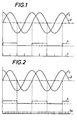
- FIG. 1 and 2 show two diagrams for explaining the principle of the correction in the position measuring system according to the invention
- FIG. 3 shows a basic circuit diagram of a position measuring system according to the invention
- FIG. 4 shows a circuit variant of FIG. 3.
- relatively simple position measuring systems are assumed. 1 and 2, it is assumed that by scanning an incremental scale with two groups of optoelectronic scanning devices in the relative adjustment of the scanning devices with respect to the measuring graduation by interconnecting the individual Receivers of the scanning devices two ideally sinusoidal or cosine-shaped signals are obtained, which are referred to as measurement signals, since their wavelength corresponds to the scale division. Ideally, the two signals 1 and 2 are offset from one another by 90 °. Since one signal always leads the other in one direction, the two signals can also be used to determine the relative adjustment direction of the scanning unit relative to the scale or the measuring graduation with the aid of suitable circuits.
- the distances between the zero crossings of each signal correspond to the width of half the measuring division, that is to say the length of a light or dark field in optoelectronic measuring devices. Since two signals offset by 90 ° are available, four counting signals shown in line 3 can be derived from the two measuring signals for each scale section according to FIG. 1 by evaluating the zero crossings of both signals 1 and 2 and generating a count signal at the respective zero crossing . By means of a multiplier circuit, however, a large number of count signals (shown on line 3a) can also be obtained from the two measurement signals according to FIG. 2. In the exemplary embodiment, it was assumed that twenty counting pulses are generated for the measuring division corresponding to a complete wavelength.
- the counting pulses occurring between two zero crossings of a measuring signal 1 or 2 must result in a specific, fixed value. If this value deviates from the setpoint, a counting error has occurred.
- the counting start is set as desired, not at the zero crossing of the reference measuring signal (signal 1 in FIGS. 1 and 2), but to start at any point.
- the zero crossing provides a clear reference point at which the target count can be determined. If an error occurs, an alarm device can be activated or the main meter reading can be corrected using correction circuits.
- a suitable circuit is provided in the position measuring system described in more detail in FIGS. 3 and 4.
- the position measuring system according to FIGS. 3 and 4 works with a measuring graduation which is attached to several scale sections 5, 5a, two of which have been shown. Between the scale sections there is a joint area 6, the size of which can hardly be precisely defined and which will only coincidentally correspond to an integral multiple of the incremental measurement graduation applied to the scale sections, which in the simplest case consists of light and dark fields of equal length.
- two optoelectronic scanning units 7, 8 are provided, each of which has an illumination device and four photo transistors or the like, which scan the scale division via mutually offset grids. included, so that each of the scanning units 7 and 8 is able to generate two measurement signals 1, 2 according to FIGS. 1 and 2.
- a control mark 9 is present on the scale section 5a, with which a further scanning unit 10 interacts and each generates a switchover command, by means of which the two scanning units 7, 8, which can be switched on alternately, subsequently in each case the unit crossing the gap 6 is switched off.
- Corresponding devices are known, for example, from our own Swiss patent 617 006.
- the measurement signals 1, 2 are fed to a multiplier circuit 13 via lines 11, 12.
- the scanning units 7 and 8 are also connected to a control switch 14 which is sensitive to the zero crossing of the signal 1.
- the counting pulses 3 and 3a arrive at a control stage 15 which serves for direction detection and pulse merging, which subsequently supplies the counting pulses and a direction signal to an up-down counter 16 which, for example, controls a display 17, but possibly also part of a machine control device can be.
- the counting pulses are on line 18 and the signal determining the counting direction of the up-down counter 16 is on line 19.
- the control switch 14 is part of a monitoring and correction circuit with a delay element 20 located in the line 18, an auxiliary counter 21, a memory 22 associated therewith and a control device 23, which in turn contains a setpoint memory.
- a control stage 15 In front of the control stage 15 there are correction stages 24, 25 in the lines coming from the multiplier circuit 13, one of which (24) serves for the addition and the other (25) for the removal of counting pulses.
- the auxiliary or correction counter 21 is designed as an overflow counter with a content corresponding to the target value of the count signals between two zero crossings of the signal 1, i.e. it sets to "zero" when the setpoint is reached.
- the counters 16 and 21 are switched to one with the aid of a zero-setting or preselection switch 26, which was indicated schematically on the control device 23, but also one similar to the scanning unit 10
- the scale marking appealing scanning unit can be set to "zero" or a certain value, but in the normal case the auxiliary counter 21 is always set to zero. If the measurement is now carried out (adjustment of the scanning units 7, 8 relative to the measuring graduation 5, 5a), the counter 16 counts the counting pulses (3 or 3a) arriving via 18 in accordance with the predetermined measuring direction which is given to it via line 19 Display 17 is displayed accordingly.
- the correction counter which also counts depending on the direction, also counts the count signals.
- These signals are first placed on the memory 22, which can be a lockable shift register, which shifts by one step with each incoming count pulse.
- memory 22 is locked (the zero pulse is used as a latch pulse) and at the same time unit 23 receives a control command from output line 27 of control switch 14 so that it compares the content of its memory with the content of locked memory 22. If the memory contents match, the lock is released again.
- the correction stage 24 or 25 is actuated, which inserts an additional pulse, which is subsequently rated as a counting pulse, between two regular counting pulses or the next following counting pulse suppressed.
- the control device 23 is preferably designed as a programmed microprocessor and contains a ring-shaped organized (RAM) memory with several memory locations. If one switches over to the other scanning unit 7 or 8 via 9-10 or it can be seen from the sequence of the control commands that a new scale section is now being traveled over, then the system switches over to the next storage location. This Storage space is occupied with a new correction value or is to be occupied when this measurement section is driven on for the first time. If a new allocation is necessary, a corresponding correction value is expediently read from the memory 22 after the second, third or a subsequent zero crossing from the scanning of this partial scale section and is adopted in the respective memory location of the control device 23.
- RAM ring-shaped organized
- an average calculator 28 is arranged between the memory 22 and the control device 23, which first averages a number of counter readings determined at the zero crossing in the respective counting direction and on the respective scale section, that is, records the most frequently occurring counter reading , and only then outputs this value as a correction value to the memory of the control device 23 formed by the microprocessor.
- the memory 22 is cleared with every control pulse of 10 and with every change of count direction.
- the invention can of course also be used in position measuring systems with circular or arcuate scales (angle measuring systems).
- the correction method can also be used in incremental position measuring systems with magnetic, inductive or capacitive scanning.
Landscapes
- Physics & Mathematics (AREA)
- General Physics & Mathematics (AREA)
- Engineering & Computer Science (AREA)
- Theoretical Computer Science (AREA)
- Length Measuring Devices By Optical Means (AREA)
- Optical Transform (AREA)
- Transmission And Conversion Of Sensor Element Output (AREA)
Description
Die Erfindung betrifft ein inkrementales Lagemeßsystem mit wenigstens zwei Gruppen von optoelektronisc hen Abtasteinrichtungen, die zur Erzeugung von wenigstens zwei gegeneinander in der Phase verschobenen Meßsignalen relativ entlang einer Meßteilung verstellbar sind, wobei die Meßsignale einer Vervielfacherschaltung zur elektronischen Unterteilung des Maßstabes und einer Richtungserkennungsstufe zuführbar sind, die ihrerseits Zähl- bzw. Steuersignale für wenigstens einen Vor-Rückwärtszähler erzeugen, dem eine Anzeige- und bzw. oder Steuereinheit nachgeordnet ist und wobei der Zählbeginn und gegebenenfalls das Zählende des Zählers auf vorwählbare Maßstabstellen einstellbar ist wie im Oberbegriff des Anspruchs 1 definiert.The invention relates to an incremental position measuring system with at least two groups of optoelectronic scanning devices which can be adjusted relatively along a measuring graduation to generate at least two measuring signals shifted in phase relative to one another, the measuring signals being able to be fed to a multiplier circuit for electronically dividing the scale and a direction detection stage. which in turn generate counting or control signals for at least one up / down counter, which is followed by a display and / or control unit and wherein the start of counting and possibly the end of counting of the counter can be set to preselectable scale positions as defined in the preamble of
Lagemeßsysteme der gegenständlichen Art können prinzipiell für die Erfassung rotatorischer oder translatorischer Verstellwege verwendet werden, wobei Hauptanwendungsgebiete bei der Winkelmessung und bei der Längenmessung liegen. Man kann aber auch andere physikalische Größen mit Hilfe geeigneter Umsetzeinrichtungen in Lageveränderungen von Abtasteinrichtungen gegenüber einer Meßteilung umsetzen und dann aus dieser Lageveränderung die jeweilige physikalische Größe bestimmen. Ein Anwendungsbeispiel hiefür ist eine Waage mit einer durch den Wiegevorgang relativ gegenüber einer Meßteilung verstellbaren Abtasteinheit. Neben einem ortsfesten Einbau der Meßteilung bzw. Ableseeinheit (die wieder wenigstens aus zwei Abtasteinrichtungen besteht) in Maschinen und Geräten sind auch ortsbewegliche Lagemeßsysteme, z.B. Handgeräte für die Längen- und Winkelmessung bekannt.Position measuring systems of the type in question can in principle be used for the detection of rotational or translational adjustment paths, the main areas of application being in angle measurement and length measurement. However, other physical variables can also be converted into changes in position of scanning devices with respect to a measuring graduation with the aid of suitable conversion devices, and the respective physical variable can then be determined from this change in position. An application example for this is a balance with a scanning unit that can be adjusted relative to a measuring graduation by the weighing process. In addition to a fixed installation of the measuring graduation or reading unit (which again consists of at least two scanning devices) in machines and devices, portable position measuring systems, for example hand-held devices for length and angle measurement, are also known.
Unter anderem kann der Zählbeginn von einem maßstabeigenen Referenzpunkt, von mehreren maßstabeigenen Referenzpunkten oder von gewählten, beispielsweise einem parallel mitlaufenden Hilfszähler, durch Nullsetzen oder Setzen eines bestimmten Zählerinhaltes bestimmten, also nur gespeicherten Referenzpunkt bestimmt werden, der bei Werkzeugmaschinen beispielsweise auf ein Werkstückende oder das Sollwerkstückende nach der Bearbeitung eingestellt wird. Das Zählende kann ebenfalls von einem Referenzpunkt aus gesteuert werden. Feste und gespeicherte Referenzpunkte ermöglichen es, trotz der Inkrementalteilung nach Fehlmessungen, Betriebsstörungen oder Betriebsabschaltungen bestimmte Einstellagen einfach zu reproduzieren.Among other things, the start of counting can be determined from a scale-specific reference point, from a number of scale-specific reference points or from selected auxiliary counters, for example a parallel counter, by zeroing or setting a specific counter content, i.e. only stored reference point, which in machine tools, for example, on a workpiece end or the target workpiece end is set after editing. The end of the count can also be controlled from a reference point. Fixed and saved reference points make it possible to easily reproduce certain setting positions despite the incremental division after incorrect measurements, malfunctions or operational shutdowns.
Eine einfache elektronische Unterteilung des Maßstabes ist beispielsweise dadurch möglich, daß man ein Paar phasenversetzter Meßsignale einer Spannungsteilerschaltung mit einer der erwünschten Anzahl von Zählsignalen entsprechenden Anzahl von Abgriffen zuführt und die Nulldurchgänge der an den Abgriffen erhaltenen Teilsignale auscodiert.A simple electronic subdivision of the scale is possible, for example, by supplying a pair of phase-shifted measurement signals to a voltage divider circuit with a number of taps corresponding to the desired number of count signals, and by coding out the zero crossings of the partial signals obtained at the taps.
Eine elektronische Unterteilung des Maßstabes ist bisher bis zu einem Verhältnis von 1 : 20 möglich bzw. üblich, so daß man bei einer ohne weiteres reproduzierbaren Inkrementalteilung mit einer Teilungslänge von 0,01 mm (es sind auch Teilungslängen bis 0,004 mm realisierbar) zu einer Messung bzw. Anzeige im Mikrometerbereich und sogar einer Zehnerpotenz darunter gelangen kann. Eine derartig feine Anzeige ist aber nur dann sinnvoll, wenn die erreichbare Meßgenauigkeit der feinen Anzeige entspricht. Entsprechend feine Unterteilungen sind auch bei Winkelmessungen möglich. Abgesehen von hier nicht näher zu behandelnden Unterteilungsfehlern durch nicht exakt eingestellte Phasenabstände der Meßsignale, die an sich durch exakte Einstellung der Abtasteinrichtungen gegeneinander und gegenüber dem Maßstab sowie durch Ausgleichsschaltungen behebbar sind, hängt die Genauigkeit der Unterteilung und damit auch die Genauigkeit der Anzeige davon ab, daß die Signalform des zu unterteilenden Meßsignales sich nicht allzusehr abhängig von der Verstellgeschwindigkeit, der jeweiligen Abtaststelle, von Schwankungen im Versorgungskreis, beispielsweise Schwankungen der Lichtstärke der Beleuchtungseinrichtung bei opto-elektronischer Abtastung, sowie von Schwankungen in der optischen Durchlässigkeit bzw. dem optischen Reflexionsvermögen des Maßstabes und von Abstandsänderungen der Abtasteinrichtungen vom Maßstab ändert. Selbstverständlich können auch Teilungsfehler des Maßstabes oder äußere Störeinflüsse Änderungen der Signalform bzw. sogar Beeinflussungen des Zählers (durch Störsignale) bewirken. Ein Sonderfall des Teilungsfehlers ergibt sich bei Lagemeßsystemen, deren Maßstab wegen leichterer Herstellbarkeit aus mehreren Teilstücken zusammengesetzt ist. Hier wird meist mit zwei wechselweise eingeschalteten, je wenigstens zwei Abtasteinrichtungen enthaltenden Abtasteinheiten gearbeitet und dabei eine wechselweise Einschaltung vorgenommen, so daß jeweils die den Stoßbereich überquerende Abtasteinheit abgeschaltet wird.Es kann praktisch ausgeschlossen werden, daß sich selbst bei genauester Justierung beim Übergang von einer Abtasteinheit auf die andere und von einem Maßstabteilstück auf das andere zum Umschaltzeitpunkt die eine Abtasteinheit exakt in jener Relativstellung zur Inkrementalteilung befindet, wie die andere Abtasteinheit zu dem von ihr abgetasteten Inkrementalteilungsbereich. Ergänzend sei darauf hingewiesen, daß bei opto-elektronischer Abtastung jede Abtasteinrichtung mehrere Teilfelder des Maßstabes durch ein der Maßstabteilung entsprechendes Gitter hindurch abtasten kann. Änderungen der Beleuchtungsstärke der Fototransistoren od.dgl. in Abhängigkeit von der Relativstellung zum Maßstab können auch durch andere Maßnahmen, beispielsweise Linsensysteme, erzeugt werden bzw. es kann sogar mit einem Pulsbetrieb der Beleuchtungseinrichtung und Erzeugung der Zählsignale aus den Pulssignalen gearbeitet werden.Up to now, an electronic division of the scale up to a ratio of 1:20 has been possible or usual, so that with an easily reproducible incremental division with a division length of 0.01 mm (division lengths up to 0.004 mm can also be realized) for a measurement or display in the micrometer range and even a power of ten below. Such a fine display is only useful if the achievable measurement accuracy corresponds to the fine display. Correspondingly fine subdivisions are also possible with angle measurements. With the exception of subdivision errors which are not to be dealt with here, due to the phase spacing of the measurement signals not being set exactly, which in itself is due to exact setting of the scanning devices relative to one another and with respect to the scale and can be remedied by equalization circuits, the accuracy of the subdivision and thus also the accuracy of the display depend on the fact that the signal shape of the measurement signal to be subdivided does not depend too much on the adjustment speed, the respective sampling point, on fluctuations in the supply circuit, for example fluctuations in the light intensity of the lighting device in the case of optoelectronic scanning, as well as of fluctuations in the optical permeability or the optical reflectivity of the scale and of changes in the distance of the scanning devices from the scale. Of course, graduation errors on the scale or external interference can also cause changes in the signal shape or even influences the counter (due to interference signals). A special case of the division error arises in the case of position measuring systems, the scale of which is composed of several sections because it is easier to manufacture. This is usually done with two alternately switched on scanning units, each containing at least two scanning devices, and alternately switched on, so that the scanning unit crossing the impact area is switched off. It can be practically excluded that even with the most precise adjustment when changing from a scanning unit to the other and from one scale section to the other at the time of switching, the one scanning unit is exactly in that position relative to the incremental division, like the other scanning unit to the incremental division region scanned by it. In addition, it should be pointed out that with optoelectronic scanning, each scanning device can scan several partial fields of the scale through a grid corresponding to the scale division. Changes in the illuminance of the photo transistors or the like. in dependence of the relative position to the scale can also be generated by other measures, for example lens systems, or it is even possible to work with pulsed operation of the lighting device and generation of the count signals from the pulse signals.
Die aufgezeigten Störeinflüsse können dazu führen, daß während der Durchführung einer Messung Zählimpulse verschluckt oder durch Störeinflüsse Störimpulse eingestreut werden, die als Zählimpulse gezählt werden, wodurch ein Meßfehler auftritt. Besonders bei einem mehrfachen Überqueren stark verschmutzter Maßstabeinheiten oder von Maßstabstoßstellen kann es zu einer Aufsummierung der einzelnen Zählfehler und damit zu größeren Meßfehlern kommen. Es ist zwar möglich und auch üblich, einzelne Messungen zu wiederholen und vor jeder Einzelmessung eine Neujustierung des Zählers durch Anfahren eines Bezugspunktes vorzunehmen, doch sind hier an sich wenigstens drei Messungen, bei denen das Ergebnis von wenigstens zweien übereinstimmt, notwendig. Wird allerdings bei diesen Messungen eine besondere Fehlerquelle, beispielsweise ein Stoßbereich von Maßstabteilstücken, jeweils gleich oft überquert, kann auch in dem übereinstimmenden Meßergebnis ein systematischer Zählfehler enthalten sein.The disturbances shown can lead to counting pulses being swallowed while a measurement is being carried out or interfering pulses being interspersed by disturbing influences, which are counted as counting pulses, as a result of which a measurement error occurs. In particular, when severely soiled scale units or scale joints are crossed several times, the individual counting errors can be added up and thus larger measurement errors. Although it is possible and also customary to repeat individual measurements and to readjust the counter by moving to a reference point before each individual measurement, at least three measurements in which the result of at least two agree are necessary. However, if a particular source of error, for example a joint area of scale sections, is crossed with the same number of times during these measurements, a systematic counting error can also be contained in the corresponding measurement result.
Die Praxis zeigt, daß Zählfehler auch richtungsabhängig verschieden groß auftreten können. Beispielsweise kommt es bei der Spaltüberquerung und Systemumschaltung manchmal in der einen Verstellrichtung zu einem anderen Zählfehler als in der anderen Verstell- bzw. Umschaltrichtung. Wenn die möglichen Zählfehler größenordnungsmäßig bei einer Messung gleich oder größer werden als das Äquivalent einer Meßteilung, dann ist an sich die elektronische Unterteilung der Meßsignale sinnlos bzw. es wird durch diese Unterteilung eine tatsächlich nicht vorhandene Genauigkeit vorgetäuscht.Practice shows that counting errors can also vary in size depending on the direction. For example, when crossing the gaps and switching the system, there is sometimes a different counting error in one direction of adjustment than in the other direction of adjustment or changeover. If the possible counting errors on the order of magnitude in a measurement become equal to or greater than the equivalent of a measuring graduation, then the electronic subdivision of the measuring signals is senseless per se or an accuracy that is actually not present is simulated by this subdivision.
Aufgabe der Erfindung ist die Schaffung eines Lagemeßsystemes, mit dessen Hilfe auftretende Zählfehler erkannt und angezeigt bzw. korrigiert werden können und zumindest eine Summierung auftretender Zählfehler verhindert wird.The object of the invention is to provide a position measuring system with the aid of which counting errors can be detected and displayed or corrected and at least a summation of occurring counting errors is prevented.
Bei einem Lagemeßsystem der eingangs genannten Art wird die gestellte Aufgabe dadurch gelöst, daß eine von den Meßsignalen und den Zählsignalen beaufschlagte Überwachungsschaltung vorgesehen ist, die einen an den Zählsignalen liegenden Korrekturzähler, einen Sollwertspeicher und einen Vergleicher aufweist und daß der Vergleicher vom Nulldurchgang wenigstens des einen Meßsignales beaufschlagt, den Zählerstand des Korrekturzählers mit dem gespeicherten Sollwert vergleicht und bei Abweichungen Korrektursignale für die Zählschaltung bzw. eine eigene Korrekturstufe in der Zählschaltung erzeugt oder eine Alarmeinrichtung einschaltet. Der Sollwert kann dem Abstand der Abtasteinheit von dem in Verstellrichtung folgenden Ende der Maßstabteilung (Inkrement) entsprechen, auf dem die Zählung begonnen hat. Selbstverständlich können entsprechende Sollstände auch zu folgenden Trennpunkten der Maßstabteilung (Übergang von einem auf das nächste Inkrement) bestimmt und verglichen werden. Vorzugsweise wird der Stand der niedrigsten Zähldekade bzw.-dekaden des Zählers mit einem gespeicherten Sollwert verglichen, der, da die Zählung keineswegs zwangsweise in der Mitte einer Teilung beginnt, für die beiden Zählrichtungen verschieden sein kann.In a position measuring system of the type mentioned at the outset, the object is achieved in that a monitoring circuit acted upon by the measuring signals and the counting signals is provided, which has a correction counter connected to the counting signals, a setpoint memory and a comparator, and in that the comparator from the zero crossing at least one Measurement signals are applied, the counter reading of the correction counter is compared with the stored target value and, in the event of deviations, correction signals are generated for the counter circuit or a separate correction stage in the counter circuit or an alarm device is switched on. The setpoint can correspond to the distance of the scanning unit from the end of the scale division (increment) following in the adjustment direction, on which the counting started. Of course, corresponding target levels can also be determined and compared at the following separating points of the scale division (transition from one increment to the next). The state of the lowest counting decade or decades of the counter is preferably compared with a stored target value which, since the counting does not necessarily start in the middle of a division, can be different for the two counting directions.
Dem Korrekturzähler kann für die letztere Möglichkeit ein Speicher zum Festhalten des beim Nulldurchgang aufgetretenen Zählstandes nachgeordnet sein, dessen Inhalt auf den Vergleicher abrufbar ist. Hier wird den praktischen Erfordernissen Rechnung getragen, bei denen ja durch die Verstellung der Abtasteinheiten gegenüber der Meßteilung fortlaufend Zählsignale auftreten. Der im Augenblick des Nulldurchganges erhaltene Momentanwert des Zählstandes wird im Speicher festgehalten und verarbeitet, wobei die Korrektur verzögert folgt. Man kann auch die Zählsignale verzögern, dem Vergleicher zuführen und dann die Korrektur vornehmen, so daß die Korrektur vor dem nächsten Nulldurchgang beendet wird, wenn weiterhin eine Meßverstellung auftritt. Im Normalfall ist, wie erwähnt, im Sollwertspeicher der Überwachungsschaltung ein dem Inkrementbruchteil der Meßteilung zwischen Einschaltpunkt des Abtastsystems und nächstem Teilungsfeldende entsprechender Wert gespeichert.For the latter option, the correction counter can be followed by a memory for holding the count that occurred at the zero crossing, the content of which can be called up on the comparator. Here is the practical Requirements taken into account, in which counting signals occur continuously due to the adjustment of the scanning units relative to the measuring graduation. The instantaneous value of the count obtained at the moment of the zero crossing is recorded in the memory and processed, with the correction following with a delay. The counting signals can also be delayed, fed to the comparator and then carried out the correction so that the correction is ended before the next zero crossing if a measurement adjustment continues to occur. Normally, as mentioned, a value corresponding to the incremental fraction of the measuring division between the switch-on point of the scanning system and the next end of the division field is stored in the setpoint memory of the monitoring circuit.
Der Sollwertspeicher kann weiters über die steuereinrichtung in vorbestimmten Betriebszuständen, insbesondere nach dem Auftreten einer bestimmten Anzahl von Korrekturbefehlen (Nulldurchgänge des Meßsignales) mit dem Inhalt des Zwischenspeichers beaufschlagbar sein.The setpoint value memory can also be loaded with the content of the intermediate memory via the control device in predetermined operating states, in particular after the occurrence of a certain number of correction commands (zero crossings of the measurement signal).
Um zu verhindern, daß ein zufällig im ersten überwachten Inkrementbruchteil vorhandener Teilungsfehler oder ein beispielsweise durch das Umschalten von einem Meßsystem auf das andere auftretender, als Zählimpuls registrierter Störimpuls zur Speicherung eines falschen Korrekturwertes führt, kann der zuletzt erwähnte Zwischenspeicher als Durchschnittsbildner für mehrere Zählfolgen des Korrekturzählers ausgebildet sein.In order to prevent a division error occurring accidentally in the first monitored incremental fraction or an interference pulse occurring as a counting pulse, for example due to the switching from one measuring system to the other, leading to the storage of an incorrect correction value, the last-mentioned buffer store can be used as an averager for several counting sequences of the correction counter be trained.
Der Korrekturzähler kann als Überlaufzähler ausgeführt sein, dessen Zählstufenzahl der elektronischen Maßstabunterteilung, also dem die Anzahl der Zählimpulse ergebenden Vielfachen der Meßimpulse bzw. Meßsignale entspricht.The correction counter can be designed as an overflow counter, the number of counting stages of which corresponds to the electronic scale subdivision, that is to say the multiple of the measuring pulses or measuring signals resulting from the number of counting pulses.
Bei der Korrektur können die Hinzufügung bzw. Wegnahme von Zählimpulsen ermöglichende Korrekturstufen vor der Richtungserkennungsstufe in den Zählimpulsleitungen liegen.In the case of the correction, correction stages which allow the addition or removal of counting pulses can lie in the counting pulse lines before the direction detection stage.
Für den Sonderfall eines Lagemeßsystemes mit einem aus mehreren Teilstücken bestehenden Maßstab und zwei in Maßstablängsrichtung versetzten, je wenigstens zwei Abtasteinrichtungen enthaltenden Abtasteinheiten, die über einen Umschalter, der jeweils die den Stoß zwischen zwei Teilstücken überquerende Abtasteinheit abschaltet, wechselweise einschaltbar sind, kann man erfindungsgemäß jedem Maßstabteilstück gesonderte Speicherplätze im Sollwertspeicher zuordnen und die einem Maßstabteilstück zugeordneten Speicherplätze vom Umschalter gesteuert mit der Vergleichseinrichtung verbinden. Vorzugsweise wird der Speicher ringförmig organisiert, wobei jedem Maßstabteilstück gesonderte Speicherplätze für beide Abtastrichtungen zugeordnet sind, die bei der jeweiligen Abtastrichtung mit der Vergleichseinrichtung verbindbar sind.For the special case of a position measuring system with a scale consisting of several sections and two scanning units offset in the longitudinal direction, each containing at least two scanning devices, which can be switched on alternately via a switch which switches off the scanning unit crossing the joint between two sections, according to the invention, anyone can Assign scale sections to separate memory locations in the setpoint memory and connect the memory locations assigned to a scale section controlled by the switch with the comparison device. The memory is preferably organized in a ring-shaped manner, with each scale section being assigned separate memory locations for both scanning directions, which can be connected to the comparison device in the respective scanning direction.
Weitere Einzelheiten und Vorteile des Erfindungsgegenstandes gehen aus der nachfolgenden Zeichnungsbeschreibung hervor.Further details and advantages of the subject matter of the invention emerge from the following description of the drawings.
In der Zeichnung ist der Erfindungsgegenstand beispielsweise veranschaulicht. Es zeigen: Fig. 1 und 2 zwei Diagramme zur Erläuterung des Prinzips der Korrektur beim erfindungsgemäßen Lagemeßsystem, Fig. 3 ein Prinzipschaltschema eines erfindungsgemäßen Lagemeßsystems und Fig. 4 eine Schaltungsvariante zu Fig. 3.The subject matter of the invention is illustrated in the drawing, for example. 1 and 2 show two diagrams for explaining the principle of the correction in the position measuring system according to the invention, FIG. 3 shows a basic circuit diagram of a position measuring system according to the invention and FIG. 4 shows a circuit variant of FIG. 3.
Bei den Ausführungsbeispielen wird von verhältnismäßig einfachen Lagemeßsystemen ausgegangen. Nach den Fig. 1 und 2 wird angenommen, daß durch Abtastung eines Inkrementalmaßstabes mit zwei Gruppen optoelektronischer Abtasteinrichtungen bei der Relativverstellung der Abtasteinrichtungen gegenüber der Meßteilung durch Zusammenschaltung der einzelnen Empfänger der Abtasteinrichtungen zwei im Idealfall sinus- bzw. kosinusförmige Signale erhalten werden, die als Meßsignale bezeichnet werden, da ihre Wellenlänge der Maßstabteilung entspricht. Die beiden Signale 1 und 2 sind gegeneinander im Idealfall um 90° versetzt. Da immer ein Signal dem anderen in einer Richtung voreilt, kann man aus den beiden Signalen auch die relative Verstellrichtung der Abtasteinheit gegenüber dem Maßstab bzw. der Meßteilung mit Hilfe geeigneter Schaltungen feststellen. Die Abstände der Nulldurchgänge jedes Signales entsprechen der Breite der halben Meßteilung, also der Länge eines Hell- bzw. Dunkelfeldes bei opto-elektronischen Meßeinrichtungen. Da man zwei um 90° gegeneinander versetzte Signale zur Verfügung hat, kann man nach Fig. 1 durch Auswertung der Nulldurchgänge beider Signale 1 und 2 und Erzeugung eines Zählsignales beim jeweiligen Nulldurchgang aus den beiden Meßsignalen für jedes Maßstabteilstück vier in der Linie 3 dargestellte Zählsignale ableiten. Durch eine Vervielfacherschaltung kann man aber aus den beiden Meßsignalen auch gemäß Fig. 2 eine Vielzahl von Zählsignalen (auf der Linie 3a dargestellt) gewinnen. Beim Ausführungsbeispiel wurde angenommen, daß für die einer vollständigen Wellenlänge entsprechenden Meßteilung zwanzig Zählimpulse erzeugt werden.In the exemplary embodiments, relatively simple position measuring systems are assumed. 1 and 2, it is assumed that by scanning an incremental scale with two groups of optoelectronic scanning devices in the relative adjustment of the scanning devices with respect to the measuring graduation by interconnecting the individual Receivers of the scanning devices two ideally sinusoidal or cosine-shaped signals are obtained, which are referred to as measurement signals, since their wavelength corresponds to the scale division. Ideally, the two
Bei richtiger Messung müssen die zwischen zwei Nulldurchgängen eines Meßsignales 1 oder 2 auftretenden Zählimpulse einen bestimmten, festen Wert ergeben. Weicht dieser Wert vom Sollwert ab, so ist ein Zählfehler aufgetreten. Man kann nun aus den Nulldurchgängen des einen der beiden Meßsignale 1 oder 2 ein Prüfsignal 4 erzeugen und jeweils beim Nulldurchgang überprüfen, ob der Sollwert an Zählimpulsen erreicht ist oder nicht. Beginn die Zählung bei Null, so entspricht der Sollwert dem Unterteilungswert der Meßsignale. Es ist aber auch ohne weiteres möglich und im Normalfall üblich, bei einem beliebigen Setzen des Zählbeginnes mit der Zählung nicht am Nulldurchgang des Bezugs-Meßsignales (in Fig. 1 und 2 das Signal 1), sondern an beliebiger Stelle zu beginnen. Hier müssen bis zum nächsten Nulldurchgang in beiden Zählrichtungen (Verstellrichtungen von Abtasteinrichtung und Maßstab) je eine bestimmte Anzahl von Zählimpulsen auftreten, wenn kein Zählfehler bzw. keine Störung vorliegt. Der Einfachheit halber wird immer nur von Zählimpulsen gesprochen, doch sind hier auch Störungen des Vor-Rückwärtszählers durch äußere Störeinflüsse, die zum Verschlucken von Zählimpulsen oder zum Vortäuschen von Zählimpulsen führen, gemeint. Jedenfalls erhält man durch den Nulldurchgang eine eindeutige Bezugsstelle, an der der Sollzählstand festgestellt werden kann. Tritt ein Fehler auf, dann kann eine Alarmeinrichtung betätigt oder über Korrekturschaltungen eine Berichtigung des Hauptzählerstandes vorgenommen werden. Eine geeignete Schaltung ist in dem in den Fig. 3 und 4 näher beschriebenen Lagemeßsystem vorgesehen.If the measurement is correct, the counting pulses occurring between two zero crossings of a
Das Lagemeßsystem nach den Fig. 3 und 4 arbeitet mit einer Meßteilung, die auf mehreren Maßstabteilstücken 5, 5a angebracht ist, von denen zwei dargestellt wurden. Zwischen den Maßstabteilstücken liegt ein Stoßbereich 6, dessen Größe sich kaum genau definieren läßt und die nur zufällig einem ganzzahligen Vielfachen der auf den Maßstabteilstücken angebrachten inkrementalen Meßteilung, der im einfachsten Fall aus gleich langen hellen und dunklen Feldern besteht, entsprechen wird.The position measuring system according to FIGS. 3 and 4 works with a measuring graduation which is attached to
Für die Abtastung des Maßstabes sind zwei optoelektronische Abtasteinheiten 7, 8 vorgesehen, die je eine Beleuchtungseinrichtung und vier über gegeneinander versetzte Gitter die Maßstabteilung abtastende Fototransistoren od.dgl. enthalten, so daß jede der Abtasteinheiten 7 und 8 in der Lage ist, zwei Meßsignale 1, 2 nach den Fig. 1 und 2 zu erzeugen. Am Maßstabteilstück 5a ist eine Steuermarke 9 vorhanden, mit der eine weitere Abtasteinheit 10 zusammenwirkt und jeweils einen Umschaltbefehl erzeugt, durch den in weiterer Folge von den beiden wechselweise einschaltbaren Abtasteinheiten 7, 8 jeweils die den Spalt 6 überquerende Einheit abgeschaltet wird. Entsprechende Einrichtungen sind beispielsweise aus dem eigenen CH-Patent 617 006 bekannt. Die Meßsignale 1, 2 werden über Leitungen 11, 12 einer Vervielfacherschaltung 13 zugeführt. Die Abtasteinheiten 7 und 8 sind ferner mit einem auf den Nulldurchgang des Signales 1 empfindlichen Steuerschalter 14 verbunden. Von der Schaltung 13 gelangen die Zählimpulse 3 bzw. 3a zu einer der Richtungserkennung und Impulszusammenführung dienenden Steuerstufe 15, die in weiterer Folge die Zählimpulse und ein Richtungssignal einem Vor-Rückwärtszähler 16 zuführt, der beispielsweise eine Anzeige 17 steuert, gegebenenfalls aber auch Teil einer Maschinensteuereinrichtung sein kann. Soweit bisher beschrieben wurde, ist die Einrichtung (mit Ausnahme der Stufe 14) bekannt. Auf der Leitung 18 liegen die Zählimpulse und auf der Leitung 19 das die Zählrichtung des Vor-Rückwärtszählers 16 bestimmende Signal.For the scanning of the scale, two optoelectronic scanning units 7, 8 are provided, each of which has an illumination device and four photo transistors or the like, which scan the scale division via mutually offset grids. included, so that each of the scanning units 7 and 8 is able to generate two
Der Steuerschalter 14 ist Bestandteil einer Überwachungs- und Korrekturschaltung mit einem in der Leitung 18 liegenden Verzögerungsglied 20, einem Hilfszähler 21, einem diesem zugeordneten Speicher 22 und einer Steuereinrichtung 23, die ihrerseits einen Sollwertspeicher enthält. Vor der Steuerstufe 15 liegen in dem von der Vervielfacherschaltung 13 kommenden Leitungen Korrekturstufen 24, 25, von denen die eine (24) für die Zugabe und die andere (25) für die Wegnahme von Zählimpulsen dient.The
Der Hilfs- oder Korrekturzähler 21 ist als Überlaufzähler mit einem dem Sollwert der Zählsignale zwischen zwei Nulldurchgängen des Signales 1 entsprechenden Inhalt ausgebildet, d.h. er stellt beim Erreichen des Sollwertes auf "Null".The auxiliary or
Zu Beginn einer Messung werden die Zähler 16 und 21 mit Hilfe eines Nullsetz- oder Vorwählschalters 26, der schematisch an der Steuereinrichtung 23 angedeutet wurde, aber auch eine der Abtasteinheit 10 ähnliche, auf eine Maßstabmarkierung ansprechende Abtasteinheit sein kann auf "Null" oder einen bestimmten Wert gesetzt, wobei aber im Normalfall der Hilfszähler 21 immer auf Null gesetzt wird. Erfolgt nun die Messung (Verstellung der Abtasteinheiten 7, 8 gegenüber der Meßteilung 5, 5a), so zählt der Zähler 16 entsprechend der vorgegebenen Meßrichtung, die ihm über die Leitung 19 angegeben wird, die über 18 eintreffenden Zählimpulse (3 oder 3a) und die Anzeige 17 wird entsprechend gestellt. Der ebenfalls richtungsabhängig zählende Korrekturzähler zählt ebenfalls die Zählsignale. Diese Signale werden zunächst auf den Speicher 22, der ein verriegelbares Schieberegister sein kann, das bei jedem einlangenden Zählimpuls um einen Schritt weiterschiebt, gelegt. Beim Nulldurchgang des Signales 1 wird der Speicher 22 verriegelt (der Nullimpuls wird als Latchimpuls verwendet) und gleichzeitig erhält die Einheit 23 einen Steuerbefehl von der Ausgangsleitung 27 des Steuerschalters 14, so daß sie den Inhalt ihres Speichers mit dem Inhalt des verriegelten Speichers 22 vergleicht. Stimmen die Speicherinhalte überein, wird die Verriegelung wieder aufgehoben. Bei Abweichungen vom Sollwert wird, je nachdem, ob der Sollwert über oder unter dem gespeicherten Zählwert des Überwachungszählers 21 liegt, die Korrekturstufe 24 oder 25 betätigt, die zwischen zwei regulären Zählimpulsen einen zusätzlichen, in weiterer Folge als Zählimpuls gewerteten Impuls einschiebt oder den nächstfolgenden Zählimpuls unterdrückt. Da die Korrekturstufen vor der Einheit 15 angeordnet sind, erfolgt eine richtungsabhängige Korrektur. Die Steuereinrichtung 23 ist vorzugsweise als programmierter Mikroprozessor ausgebildet und enthält einen ringförmig organisierten (RAM-)Speicher mit mehreren Speicherplätzen. Wird über 9-10 von einer auf die andere Abtasteinheit 7 bzw. 8 umgeschaltet bzw. läßt sich aus der Reihenfolge der Steuerbefehle entnehmen, daß nun ein neues Maßstabteilstück befahren wird, dann wird auf den nächsten Speicherplatz umgeschaltet. Dieser Speicherplatz ist mit einem neuen Korrekturwert belegt oder beim erstmaligen Befahren des entsprechenden Maßstabteilstückes während dieser Messung zu belegen. Ist eine Neubelegung notwendig, wird zweckmäßigerweise nach dem zweiten, dritten oder einem folgenden Nulldurchgang aus der Abtastung dieser Maßstabteilstrecke ein entsprechender Korrekturwert am Speicher 22 abgelesen und in den jeweiligen Speicherplatz der Steuereinrichtung 23 übernommen. Es wird hier von der Annahme ausgegangen, daß der am ersten Nulldurchgang auftretende Stand des Zählers 21 noch mit Fehlern behaftet sein kann. Man kann auch Speicherplätze für jede der beiden Verstellrichtungen vorsehen. Zumindest für die jeweilige Messung ist jedem Maßstabteilstück, 5, 5a usw. im Speicher des Mickroprozessors 23 (Steuereinrichtung) wenigstens ein Korrekturwert bzw. zwei richtungsabhängige Korrekturwerte zugeordnet, die beim jeweiligen Neubefahren des entsprechenden Maßstabteilstückes jeweils beim Nullimpuls abgerufen und mit dem Zählerstand des Korrekturzählers 21 verglichen werden. Fig. 4 zeigt eine Schaltungsvariante, bei der zwischen dem Speicher 22 und der Steuereinrichtung 23 ein Durchschnittsbildner 28 angeordnet ist, der zunächst aus mehreren, am Nulldurchgang bei der jeweiligenZählrichtung und am jeweiligen Maßstabteilstück festgestellten Zählerständen einen Durchschnitt bildet, d.h. den am häufigsten vorkommenden Zählerstand festhält, und dann erst diesen Wert als Korrekturwert an den Speicher der vom Mikroprozessor gebildeten Steuereinrichtung 23 abgibt. Der Speicher 22 wird bei jedem Steuerimpuls von 10 und bei jeder Zählrichtungsänderung gelöscht.At the start of a measurement, the
Die Erfindung kann selbstverständlich auch bei Lagemeßsystemen mit kreis- oder bogenförmigen Maßstäben (Winkelmeßsystemen) verwendet werden. Das Korrekturverfahren ist prinzipiell auch bei inkrementalen Lagemeßsystemen mit magnetischer, induktiver oder kapazitiver Abtastung anwendbar.The invention can of course also be used in position measuring systems with circular or arcuate scales (angle measuring systems). In principle, the correction method can also be used in incremental position measuring systems with magnetic, inductive or capacitive scanning.
Claims (9)
- An incremental locating system having at least two groups (7, 8) of opto-electronic scanning means adjustable along a measurement scale and adapted to produce at least two non-cophasal measurement signals (1, 2), one of the measurement signals (1, 2), the same having a wavelength corresponding to the scale graduation, being adapted to be supplied to a multiplier circuit arrangement (13) for electronic scale subdivision and to a direction-identifying stage (15) which produce counting or control signals for a forwards and backwards counter (16) which is followed by a display and/or control unit, the start of counting and possibly the end of counting of the counter (16) being adjustable to preselectable places on the scale, characterised in that a monitoring circuit arrangement (14, 20 - 28) actuated by the measurement signals (1, 2) and the counting signals (3, 3a) is provided and has a correction counter (21) connected to the counting signals, a set-value store and a comparator (23), and the same responds to the passage through zero of at least one measurement signal (1) by comparing the state of the correction counter with the stored set value, and in the event of deviations, by producing correction signals for the counting circuit arrangement (15 - 17) or for an independent correction stage (25, 26) therein or by actuating warning means.
- A system according to claim 1, characterised in that a store (22) for retaining the counter state associated with the passage through zero is disposed after the correction counter (21) and the content of the latter store can be called up to the comparator (23).
- A system according to claim 1 or 2, characterised in that a value corresponding to the incremental function of the measuring scale between the switch-on point of the scanning system and the next graduation boundary is stored in the set-value store of the monitor means (23).
- A system according to claim 3, characterised in tht the set-value store is adapted to be actuated with the content of the intermediate store (22; 28) by way of the control means (23) at predetermined operative states, more particularly after the appearance of a predetermined number of correction instructions (passages of the measurement signal through zero).
- A system according to claim 4, characterised in that the intermediate store (22, 28) is an average former for a number of counts of the correction counter (21).
- A system according to any of claims 1 to 5, characterised in that the correction counter (21) is an overflow counter whose number of counting stages corresponds to the electronic scale subdivision - i.e., to that multiple of the measuring pulses which produces the number of counting pulses.
- A system according to any of claims 1 to 6, characterised in that correction stages (24, 25) enabling counting pulses to be added or removed are disposed in the counting pulse lines before the direction-identifying stage (25).
- A system according to any of claims 1 to 7 having a scale comprising a number of components and two scanning units which are offset lengthwise of the scale and which each comprise at least two scanning means and which can be energised alternately by way of a selector which switches off the scanning unit bridging the gap between two components, characterised in that special storage places in the set-value store (23) are associated with each scale component (5, 5a) and the storage places associated with one scale component can be connected under the control of the selector (10) to the comparator (22, 23).
- A system according to claim 8, characterised in that separate storage places for both scanning directions are associated with each scale component (5, 5a) in the set-value store and are adapted to be connected to the comparator (22, 23) in the particular scanning direction concerned.
Priority Applications (2)
| Application Number | Priority Date | Filing Date | Title |
|---|---|---|---|
| DE8787890154T DE3772989D1 (en) | 1987-07-06 | 1987-07-06 | INCREMENTAL POSITION MEASURING SYSTEM. |
| EP19870890154 EP0298183B1 (en) | 1987-07-06 | 1987-07-06 | Incremental position measuring system |
Applications Claiming Priority (1)
| Application Number | Priority Date | Filing Date | Title |
|---|---|---|---|
| EP19870890154 EP0298183B1 (en) | 1987-07-06 | 1987-07-06 | Incremental position measuring system |
Publications (2)
| Publication Number | Publication Date |
|---|---|
| EP0298183A1 EP0298183A1 (en) | 1989-01-11 |
| EP0298183B1 true EP0298183B1 (en) | 1991-09-11 |
Family
ID=8198521
Family Applications (1)
| Application Number | Title | Priority Date | Filing Date |
|---|---|---|---|
| EP19870890154 Expired - Lifetime EP0298183B1 (en) | 1987-07-06 | 1987-07-06 | Incremental position measuring system |
Country Status (2)
| Country | Link |
|---|---|
| EP (1) | EP0298183B1 (en) |
| DE (1) | DE3772989D1 (en) |
Families Citing this family (3)
| Publication number | Priority date | Publication date | Assignee | Title |
|---|---|---|---|---|
| JP2697919B2 (en) * | 1989-09-29 | 1998-01-19 | キヤノン株式会社 | Signal interpolation circuit and displacement measuring device provided with the circuit |
| JP3232795B2 (en) * | 1992-08-06 | 2001-11-26 | キヤノン株式会社 | Detector |
| EP1610096B2 (en) † | 1997-04-16 | 2012-09-05 | Dr. Johannes Heidenhain GmbH | Position measuring device and method for operating a position measuring device |
Family Cites Families (2)
| Publication number | Priority date | Publication date | Assignee | Title |
|---|---|---|---|---|
| DE2457376B2 (en) * | 1974-12-04 | 1980-12-18 | Institutul De Cercetari Si Proiectari Automatizari, Bukarest | Method and device for adaptive correction of digital length measurement for incremental or quasi-incremental encoders |
| AT392536B (en) * | 1984-07-06 | 1991-04-25 | R S F Elektronik Ohg Rechtsfor | LINEAR, INCREMENTAL MEASURING SYSTEM |
-
1987
- 1987-07-06 EP EP19870890154 patent/EP0298183B1/en not_active Expired - Lifetime
- 1987-07-06 DE DE8787890154T patent/DE3772989D1/en not_active Expired - Fee Related
Also Published As
| Publication number | Publication date |
|---|---|
| DE3772989D1 (en) | 1991-10-17 |
| EP0298183A1 (en) | 1989-01-11 |
Similar Documents
| Publication | Publication Date | Title |
|---|---|---|
| DE2952106C2 (en) | Photoelectric incremental length or angle measuring device | |
| EP0268558B1 (en) | Apparatus for measuring lengths or angles | |
| DE4428590C2 (en) | Position measuring device | |
| DE2730715C2 (en) | Device for length measurement | |
| DE3734072C2 (en) | ||
| EP0390770B1 (en) | Method for the electronic correction of position error in an incremental measuring system and measuring system for implementation of the method | |
| AT410485B (en) | POSITION MEASURING DEVICE | |
| AT394781B (en) | INCREMENTAL MEASURING SYSTEM | |
| EP0066682B1 (en) | Positioning device | |
| DE3306325C2 (en) | ||
| EP0298183B1 (en) | Incremental position measuring system | |
| DE1673887A1 (en) | Arrangement for determining the position of two parts that can move relative to one another | |
| DE2847779A1 (en) | DEVICE FOR POSITION DETECTION IN NUMERICALLY CONTROLLED MACHINE TOOLS | |
| CH666348A5 (en) | METHOD FOR EVALUATING MEASURING SIGNALS OBTAINED BY SCANNING AN INCREMENTAL SCALE WITH A SCANING UNIT, AND MEASURING DEVICE FOR CARRYING OUT THIS METHOD. | |
| CH417979A (en) | Measuring device for determining the size and direction of the movement of a carrier having a periodic, approximately sinusoidal recording | |
| AT385355B (en) | INCREMENTAL POSITION MEASURING SYSTEM | |
| DE3638569C2 (en) | ||
| DE2124573C3 (en) | Device for the time control of the rifle flight on a loom | |
| DE2333698B1 (en) | Digital position encoder | |
| DE4009749C2 (en) | ||
| DE1811961A1 (en) | Arrangement for setting angular positions | |
| EP0604722B1 (en) | Device for measuring lengths or angles | |
| DE2747208A1 (en) | MEASURING DEVICE, IN PARTICULAR LENGTH MEASURING DEVICE ON MACHINE TOOLS OR DGL. | |
| DE2812187C2 (en) | Device for position detection in numerically controlled machine tools | |
| DE1463440A1 (en) | Automatic adjustment system for machine tool |
Legal Events
| Date | Code | Title | Description |
|---|---|---|---|
| PUAI | Public reference made under article 153(3) epc to a published international application that has entered the european phase |
Free format text: ORIGINAL CODE: 0009012 |
|
| AK | Designated contracting states |
Kind code of ref document: A1 Designated state(s): BE CH DE FR GB IT LI LU NL SE |
|
| 17P | Request for examination filed |
Effective date: 19890613 |
|
| 17Q | First examination report despatched |
Effective date: 19901130 |
|
| GRAA | (expected) grant |
Free format text: ORIGINAL CODE: 0009210 |
|
| AK | Designated contracting states |
Kind code of ref document: B1 Designated state(s): BE CH DE FR GB IT LI LU NL SE |
|
| REF | Corresponds to: |
Ref document number: 3772989 Country of ref document: DE Date of ref document: 19911017 |
|
| ITF | It: translation for a ep patent filed |
Owner name: STUDIO CONS. BREVETTUALE S.R.L. |
|
| GBT | Gb: translation of ep patent filed (gb section 77(6)(a)/1977) | ||
| ET | Fr: translation filed | ||
| PLBE | No opposition filed within time limit |
Free format text: ORIGINAL CODE: 0009261 |
|
| STAA | Information on the status of an ep patent application or granted ep patent |
Free format text: STATUS: NO OPPOSITION FILED WITHIN TIME LIMIT |
|
| 26N | No opposition filed | ||
| PGFP | Annual fee paid to national office [announced via postgrant information from national office to epo] |
Ref country code: GB Payment date: 19930625 Year of fee payment: 7 |
|
| PGFP | Annual fee paid to national office [announced via postgrant information from national office to epo] |
Ref country code: SE Payment date: 19930707 Year of fee payment: 7 Ref country code: LU Payment date: 19930707 Year of fee payment: 7 |
|
| PGFP | Annual fee paid to national office [announced via postgrant information from national office to epo] |
Ref country code: FR Payment date: 19930720 Year of fee payment: 7 |
|
| PGFP | Annual fee paid to national office [announced via postgrant information from national office to epo] |
Ref country code: DE Payment date: 19930721 Year of fee payment: 7 |
|
| PGFP | Annual fee paid to national office [announced via postgrant information from national office to epo] |
Ref country code: BE Payment date: 19930730 Year of fee payment: 7 |
|
| PGFP | Annual fee paid to national office [announced via postgrant information from national office to epo] |
Ref country code: NL Payment date: 19930731 Year of fee payment: 7 |
|
| PGFP | Annual fee paid to national office [announced via postgrant information from national office to epo] |
Ref country code: CH Payment date: 19930831 Year of fee payment: 7 |
|
| EPTA | Lu: last paid annual fee | ||
| PG25 | Lapsed in a contracting state [announced via postgrant information from national office to epo] |
Ref country code: LU Free format text: LAPSE BECAUSE OF NON-PAYMENT OF DUE FEES Effective date: 19940706 Ref country code: GB Effective date: 19940706 |
|
| PG25 | Lapsed in a contracting state [announced via postgrant information from national office to epo] |
Ref country code: SE Effective date: 19940707 |
|
| PG25 | Lapsed in a contracting state [announced via postgrant information from national office to epo] |
Ref country code: LI Effective date: 19940731 Ref country code: CH Effective date: 19940731 Ref country code: BE Effective date: 19940731 |
|
| BERE | Be: lapsed |
Owner name: RSF-ELEKTRONIK G.M.B.H. Effective date: 19940731 |
|
| EUG | Se: european patent has lapsed |
Ref document number: 87890154.5 Effective date: 19950210 |
|
| PG25 | Lapsed in a contracting state [announced via postgrant information from national office to epo] |
Ref country code: NL Effective date: 19950201 |
|
| GBPC | Gb: european patent ceased through non-payment of renewal fee |
Effective date: 19940706 |
|
| NLV4 | Nl: lapsed or anulled due to non-payment of the annual fee | ||
| PG25 | Lapsed in a contracting state [announced via postgrant information from national office to epo] |
Ref country code: FR Effective date: 19950331 |
|
| REG | Reference to a national code |
Ref country code: CH Ref legal event code: PL |
|
| PG25 | Lapsed in a contracting state [announced via postgrant information from national office to epo] |
Ref country code: DE Effective date: 19950401 |
|
| EUG | Se: european patent has lapsed |
Ref document number: 87890154.5 |
|
| REG | Reference to a national code |
Ref country code: FR Ref legal event code: ST |
|
| PG25 | Lapsed in a contracting state [announced via postgrant information from national office to epo] |
Ref country code: IT Free format text: LAPSE BECAUSE OF NON-PAYMENT OF DUE FEES;WARNING: LAPSES OF ITALIAN PATENTS WITH EFFECTIVE DATE BEFORE 2007 MAY HAVE OCCURRED AT ANY TIME BEFORE 2007. THE CORRECT EFFECTIVE DATE MAY BE DIFFERENT FROM THE ONE RECORDED. Effective date: 20050706 |