EP0295146B1 - Supervised, interactive alarm reporting system - Google Patents
Supervised, interactive alarm reporting system Download PDFInfo
- Publication number
- EP0295146B1 EP0295146B1 EP88305368A EP88305368A EP0295146B1 EP 0295146 B1 EP0295146 B1 EP 0295146B1 EP 88305368 A EP88305368 A EP 88305368A EP 88305368 A EP88305368 A EP 88305368A EP 0295146 B1 EP0295146 B1 EP 0295146B1
- Authority
- EP
- European Patent Office
- Prior art keywords
- premises
- central facility
- derived channel
- supervised
- channel unit
- Prior art date
- Legal status (The legal status is an assumption and is not a legal conclusion. Google has not performed a legal analysis and makes no representation as to the accuracy of the status listed.)
- Expired - Lifetime
Links
Images


Classifications
-
- G—PHYSICS
- G08—SIGNALLING
- G08B—SIGNALLING OR CALLING SYSTEMS; ORDER TELEGRAPHS; ALARM SYSTEMS
- G08B25/00—Alarm systems in which the location of the alarm condition is signalled to a central station, e.g. fire or police telegraphic systems
-
- G—PHYSICS
- G08—SIGNALLING
- G08B—SIGNALLING OR CALLING SYSTEMS; ORDER TELEGRAPHS; ALARM SYSTEMS
- G08B25/00—Alarm systems in which the location of the alarm condition is signalled to a central station, e.g. fire or police telegraphic systems
- G08B25/01—Alarm systems in which the location of the alarm condition is signalled to a central station, e.g. fire or police telegraphic systems characterised by the transmission medium
- G08B25/10—Alarm systems in which the location of the alarm condition is signalled to a central station, e.g. fire or police telegraphic systems characterised by the transmission medium using wireless transmission systems
-
- G—PHYSICS
- G08—SIGNALLING
- G08B—SIGNALLING OR CALLING SYSTEMS; ORDER TELEGRAPHS; ALARM SYSTEMS
- G08B25/00—Alarm systems in which the location of the alarm condition is signalled to a central station, e.g. fire or police telegraphic systems
- G08B25/01—Alarm systems in which the location of the alarm condition is signalled to a central station, e.g. fire or police telegraphic systems characterised by the transmission medium
- G08B25/08—Alarm systems in which the location of the alarm condition is signalled to a central station, e.g. fire or police telegraphic systems characterised by the transmission medium using communication transmission lines
-
- G—PHYSICS
- G08—SIGNALLING
- G08B—SIGNALLING OR CALLING SYSTEMS; ORDER TELEGRAPHS; ALARM SYSTEMS
- G08B29/00—Checking or monitoring of signalling or alarm systems; Prevention or correction of operating errors, e.g. preventing unauthorised operation
- G08B29/16—Security signalling or alarm systems, e.g. redundant systems
Definitions
- the present invention relates generally to remote alarm reporting systems, and in particular, to a supervised alarm reporting system which is capable of providing enhanced security.
- a variety of security systems have been developed to satisfy the ever-increasing need for the remote monitoring of various premises, including both business and home applications. Generally, this is accomplished by providing the premises with a local terminal, or reporting unit, which is capable of receiving signals from various sensors placed throughout the premises, interpreting such signals, and interacting with a central office or station to advise the central facility of potential alarm conditions.
- the sensors communicating with the local terminal may be used to provide any of a variety of functions, including smoke and fire detection, the detection of intruders (i.e., possible break-ins), or to monitor local conditions such as temperature, pressure or other desired parameters.
- the corresponding central facility might constitute any of a number of private companies which have been established for security or other monitoring purposes. The key to the effectiveness and integrity of the system provided often depends upon the means which are used to establish communications between the local terminal provided at the premises and the monitoring equipment provided at the central facility. A number of systems have therefore been advised to provide such communications.
- the local terminal provided at the remote premises is connected to the switched telephone line network associated with the premises, to establish remote communications.
- communications are initiated by the local terminal, which automatically dials the central facility when a potential alarm event has been detected (one-way communications). While such communications may be accomplished by voice (a recorded message), the current trend is for such communications to be accomplished through digital communications, which are capable of providing more detailed information regarding the potential alarm condition.
- Communications via the switched telephone line network are popular because they are inexpensive, well proven and reliable.
- the switched telephone line network is already in place, readily accessible, and serviced by a third party. A cost effective security system results.
- the central facility is permitted to periodically interrogate the local terminal at the remote premises, to determine its status. In addition to indicating whether or not there are any alarm conditions, this also has the benefit of verifying that the communication lines are intact.
- a tone having a frequency below the audible range, which is transmitted by the local terminal at specified times. Again, in addition to the reporting function of this tone, this additionally provides a means for verifying the integrity of the communicating telephone lines.
- Such derived channel systems therefore have the advantage of indicating whether or not the system is operational, and is properly reporting its condition. This avoids the potential "blackouts" inherent in one-way communicating systems, thereby serving to significantly enhance security.
- Yet another system involves the replacement of wired lines with radio communications. While it is significantly more difficult to "cut" radio communications between the local terminal and the central facility, such jamming techniques do exist. Consequently, a one-way radio system, although more reliable than a wired one-way system, will still suffer from the disadvantage that the central facility is not made aware of whether or not the system is in operation. A two-way radio system would enable a supervisory function to be added. However, this requires continuous two-way communications by way of radio. Such systems are therefore subject to significant limitations in view of the regulatory constraints which are in place regarding the use of radio waves, and in terms of the number of frequencies which are available for use in a particular system (limiting the number of possible installations). Yet another factor to consider is the significant cost of installation and maintenance which such a system necessarily entails.
- EP-A-11444 discloses an alarm reporting system (Figs 1, 2) for providing communication between one or more event sensors associated with a mobile site (motor vehicle) and a facility for monitoring the event sensors at said mobile site, comprising a terminal unit for receiving signals from said event sensors, and means for establishing communication between said terminal unit and said monitoring facility.
- FR-A-2295506 discloses an alarm reporting system having a local terminal comprising a supervised derived channel communicator, and a one-way radio communicator, which are connected by a control unit which provides for interactive operation of the derived channel unit and the radio transmitter according to the alarm conditions which may arise at the premises, and the existing condition of the equipment comprising the local terminal unit.
- a supervised, interactive alarm reporting system for providing communication between one or more event sensors associated with a premises, and a central facility for monitoring the sensors at said premises, comprising: first means for establishing communication between said sensors and said central facility using wired communicating lines; second means for establishing communication between said sensors and said central facility using radio transmissions; and means connecting said first means and said second means for controlling operation of the first means and the second means according to the condition of the event sensors associated with said premises, and the condition of said first means and said second means, wherein said first means is a derived channel unit and said second means is a radio transmitter, and wherein said connecting means operates to establish communication with said central facility using said derived channel unit during normal operating conditions, the system characterised in that said connecting means includes means for periodically testing said radio transmitter responsive to periodic testing associated with said derived channel unit.
- the supervised derived channel unit operates to advise the associated central station of the conditions at the monitored premises.
- the radio transmitter is activated to advise the central station of the current status of the system. This alerts the central station to the failure, and also indicates the existing condition of the premises. If the premises are in proper condition, an equipment failure is indicated and steps are taken to repair the fault in due course. If there is an alarm condition at the premises, the central station will be advised of this by the radio transmitter, allowing appropriate measures to be taken.
- the central station is made aware of the simultaneous failure since the supervised, derived channel unit will cease to operate and the radio transmitter will not follow this cessation of activity with an appropriate report. This will result in a declared break-in. However, since the probability against both units failing simultaneously is extremely high, a declared break-in is justified.
- the one-way radio communications which are used are preferably accomplished by means of the cellular telephone network.
- This not only provides the above-discussed operational functions, but also makes use of an existing network which is installed and serviced by third parties. Since actual use of the cellular telephone network is kept to a minimum as a result of the manner of operation of the system, the marginal costs of using the cellular telephone network are kept to a minimum.
- use of the cellular telephone network has the added advantage of permitting simultaneous communications with both the central station which is monitoring the premises, as well as mobile units associated with the central station. Such mobile units may include mobile patrol vehicles, or mobile service vehicles, which can share in the responsibility of servicing a significant number of installations.
- Fig. 1 is a schematic representation of the supervised, interactive alarm reporting system of the present invention.
- Fig. 2 is a schematic view showing the construction of the controlling interface.
- Fig. 3 is a timing diagram illustrating the interactive operation of the foregoing components.
- Fig. 4 is a flow diagram illustrating the steps taken at the central station to interpret the signals received from the local terminal unit.
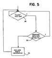
- Fig. 5 is a flow diagram illustrating steps which may be taken at the central station to periodically test the integrity of the system.
- Fig. 1 generally illustrates the supervised, interactive alarm reporting system 1 of the present invention.
- Those portions of the system 1 which are located at the premises 2 to be monitored generally include one or more sensors 3 which are capable of providing signals to a local terminal unit 4.
- sensors 3 Any of a variety of different types of sensors 3 may be used in connection with such a system, including smoke detectors, fire detectors, various detectors for determining intrusions such as contact switches, light sensitive circuits and ultrasonic circuits, as well as any of a number of parameter sensors such as temperature sensors, pressure sensors, timing devices or the like.
- any of a number of parameter sensors such as temperature sensors, pressure sensors, timing devices or the like.
- a single sensor may be provided, or any number of plural sensors may be utilized in operative combination. In any event, such sensors would be operatively connected to the local terminal unit 4 for ultimate (serial) processing as will be described more fully below.
- the terminal unit 4 is essentially comprised of three interactive units.
- the first of these units is a derived channel unit 5 which is capable of communicating with a central station 10 via the switched telephone line network 8. Any of a variety of derived channel units 5 could be used for this purpose. However, in accordance with the present invention it is preferred that the derived channel unit 5 constitute a "Subscriber Terminal Unit" of the type manufactured by Base 10 Systems, Inc., Trenton, New Jersey. This unit is preferred in view of the supervisory capabilities which it provides. These supervisory capabilities are described with reference to U.S. Patent No. 4,442,320, the subject matter of which is incorporated by reference as if fully set forth herein.
- the local terminal unit 4 also includes a radio transmitter 6 which is capable of communicating with the central station 10 by wireless communications.
- the radio transmitter 6 operate to transmit signals via the cellular telephone network 9 for reasons which will become apparent from the description which is provided below.
- the local terminal unit 4 incorporates a controlling interface 7 which operatively connects the derived channel unit 5 and the radio transmitter 6 to provide a supervised, interactive alarm signal processor, the operation of which will now be more fully discussed.
- the derived channel unit 5 is preferably a supervised unit, while the radio transmitter 6 is preferably configured as a non-supervised, one-way transmitter.
- the reason for this is that in the normal course of operations, the cost effective, supervised reporting capabilities of a derived channel unit 5 will be sufficient, and the relatively expensive cost of operating the radio transmitter 6 will be unnecessary.
- the supervised, derived channel unit 5 will therefore normally operate to keep the central station 10 advised as to the status of the premises 2, in cost effective fashion.
- the radio transmitter 6 will essentially remain dormant, keeping the impact (load) on the radio transmission network, in this case preferably the cellular telephone network, to a minimum. In addition to reducing costs, this allows a maximum number of local terminal units to be operatively associated with a particular central station without compromising the capabilities of such wireless communications.
- the derived channel unit 5 ceases to report. This may be the result of an equipment failure of the derived channel unit 5, an interruption or break in the switched telephone line network 8 due to servicing, accident or the like, or a potential break-in.
- the derived channel unit 5 In the event that the cessation of activity is the result of an equipment failure in the derived channel unit 5, the derived channel unit 5 will be unable to complete its supervisory interrogation sequence. As a result, the internal verification systems of the derived channel unit 5 (in this case the "Subscriber Terminal Unit” distributed by Base 10 Systems, Inc.) will provide an output indicating the occurrence of a fault. This output may then be used to develop a fault signal, which is applied at 11 in Fig. 2 of the drawings. The fault signal 11 is simultaneously applied to the input of an enabling circuit 12 and to the input of a programmable trigger generator 13.
- the internal verification systems of the derived channel unit 5 in this case the "Subscriber Terminal Unit" distributed by Base 10 Systems, Inc.
- This output may then be used to develop a fault signal, which is applied at 11 in Fig. 2 of the drawings.
- the fault signal 11 is simultaneously applied to the input of an enabling circuit 12 and to the input of a programmable trigger generator 13.
- the enabling circuit and the programmable trigger generator are, in essence, monostable circuits which are capable of developing appropriate pulses responsive to the fault signal 11, as will be described more fully below, which are in turn applied to the first and second inputs of an AND circuit 14.
- Coincidence between the signals produced by the enabling circuit 12 and the programmable trigger generator 13 will cause an output to be developed at the AND circuit 14, which is then introduced to the first input of an OR circuit 15. This signal will in turn be passed through the OR circuit 15, for output at 16.
- the output 16 is in turn applied to the radio transmitter 6, activating the radio transmitter 6.
- Activation of the radio transmitter 6 causes (preferably immediately) the status of the premises 2 to be transmitted to the central station 10 via the cellular telephone network 9.
- the central station 10 is made aware of the fault in the derived channel unit 5 of the terminal unit 4, and of the existing status of the sensors 3 associated with the premises 2. With this information, the central station 10 is able to make a decision as to whether or not there is an alarm condition which requires a response, or if there is simply a fault which requires eventual servicing.
- the radio transmitter 6 remains available to advise the central station 10 of any changes in the status of the local sensors 3 (i.e., alarm events).
- the radio transmitter 6 is preferably a non-supervised, one-way unit. Accordingly, after the initial transmission of information as previously described, the radio transmitter 6 could then be subjected to tampering, without the central station 10 becoming aware of such triggering. However, by properly programming the programmable trigger generator 13, this problem can be overcome as follows.
- Fig. 3 of the drawings various timing sequences associated with the controlling interface 7 are illustrated.
- the fault signal 11 is produced upon discontinuance of the operation of the derived channel unit 5.
- the enabling circuit 12 operates to develop an enabling signal 17 for application to the first input of the AND circuit 14, while the programmable trigger generator 13 operates to develop its own programmed sequence for application to the second input of the AND circuit 14, as follows.
- the output of the programmable trigger generator 13 could be established in accordance with the sequence 11 illustrated in Fig. 3. This would provide an initial indication of the fault, and maintain radio communications, but would not provide any supervisory capabilities.
- the output of the programmable trigger generator 13 could be modified to establish the sequence 18 shown in Fig. 3. This would be accomplished by programming the programmable trigger generator 13 with a specified duration (T), frequency (f), and pulse width which are preferably variable (by the subscriber) to suit the user's specific requirements. Increasing the duration and/or frequency would increase the security provided, with an attendant increase in costs associated with the periodic excercise of the radio transmitter 6. Decreasing the duration and/or frequency would have the opposite effect. Nevertheless, a supervisory function would result as follows.
- the central station 10 will begin to receive communications from the radio transmitter 6. As will be discussed more fully below, the central station 10 is made aware of (programmed to expect) the periodic re-transmissions which are to occur in accordance with the selected sequence developed within the programmable trigger generator 13. The central station 10 will therefore be looking for these periodic transmissions to verify that the radio transmitter 6 has not been tampered with. This will also serve to periodically advise the central station 10 of the status of the premises 2. Failure to receive a scheduled transmission (or if desired, a contiguous pair of transmissions) will signify that the radio transmitter 6 is no longer operational.
- the periodic transmissions of the programmable trigger generator 13 could be continued for a significant period of time, if desired. Indeed, the periodic transmissions could be maintained indefinitely, provided the enabling signal 17 (which is provided to allow the installer of the system to limit radio supervision) is also correspondingly maintained, until such time as the derived channel unit 5 could be repaired.
- Such periodic transmissions are accomplished as a result of the coincidence of the enabling signal 17 and one of the pulses developed by the programmable trigger generator 13, within the AND circuit 14. This provides a signal to the OR circuit 15, which will in turn be passed to the radio transmitter 6 as previously described.
- a restore signal such as is represented by the sequence 19 shown in Fig. 3 is provided to reset the programmable trigger generator 13, at 20 in Fig. 2. This operates to terminate the output and the AND circuit 14, restoring the terminal unit 4 to its normal operating condition.
- Fig. 4 illustrates the nature of these operations.
- activity at the central station 10 commences when it is determined that one of the derived channel units 5 is no longer responding, at 21.
- the central station 10 would then search for the corresponding radio transmission which is to result from the identified failure of the derived channel unit 5, if the particular subscriber is provided with such a capability, as determined at 22 (some subscribers may only be provided with supervised derived channel units, without the enhancement of a radio backup).
- a test is then made at 23 to determine whether or not the anticipated transmission has been received (within a defined tolerance). It will be understood that the timing of this test must therefore be programmed to correspond to the timing of the sequence entered into the programmable trigger generator 13, according to the requirement of the subscriber.
- a message 25 is displayed to alert the central station 10 of the failure of the derived channel unit 5 so that appropriate steps may be taken to repair the problem in due course.
- the derived channel unit 5 may also cease to report due to an interruption or break in the switched telephone line network 8, or due to tampering in the course of a break-in.
- the first of these possibilities will result in a non-responding derived channel unit 5, causing further operations to proceed as previously described, until the fault with the communicating line is repaired.
- the radio transmitter 6 will operate to keep the central station 10 advised of the status of the premises 2.
- re-established communications with the derived channel unit 5 will reset the terminal unit 4 (at the reset 20), returning the local terminal unit 4 to its normal operating condition.
- the second of these possibilities will cause an alarm condition to occur, which will be transmitted to the central station 10 by the radio transmitter 6, enabling appropriate personnel to be dispatched to the premises 2.
- the local terminal unit 4 need take no further action in such case since the derived channel unit 5 is fully supervised.
- the central station 10 remains in continuous contact with the premises 2, and is advised of its status.
- the central station 10 will not be able to proceed through the sequence previously described, since the initial radio transmission will not be received at the prescribed time. Again, since the probability of a simultaneous failure of the radio transmitter 6 and the derived channel unit 5 is quite low, a declared break-in is justified, and appropriate personnel are dispatched.
- the reliability, and therefore the predictability of this sequence can be further enhanced if the radio transmitter 6 is periodically tested to verify that it is operational. This may be accomplished by the testing procedure which is described with reference to Fig. 5. As previously indicated, the derived channel unit 5 is supervised, and is therefore periodically tested to verify its integrity. A test which is conventionally provided in connection with the earlier identified "Subscriber Terminal Unit” of Base 10 Systems, Inc. involves the periodic (usually each 24 hour period) transmission of a "close" signal to the "Subscriber Terminal Unit", which in turn provides an acknowledgment of this signal. This acknowledgment signal is also advantageously applied to the controlling interface 7, at 27, to provide a periodic check of the radio transmitter 6 by coupling the signal provided at 27 through the OR circuit 15 and to the radio transmitter 6. With reference to Fig.
- this test is initiated at 28, followed by a check to verify receipt of the radio transmission (within a prescribed tolerance), at 29. If so, the test is complete until the next testing period. If not, the radio transmitter 6 is declared inoperative, at 30, and steps are taken to dispatch appropriate personnel to repair the unit. Other available signals may be used, as desired, to perform similar testing of this nature.
- the derived channel unit 5 and the radio transmitter 6 cease to function, a presumption is made that a significant problem exists at the premises 2, and a break-in is immediately declared. Appropriate personnel are then dispatched to the premises 2 to deal with the situation.
- the derived channel unit 5 and the radio transmitter 6 are preferably provided with a battery back-up to account for power failures and the like, so that the probability of a simultaneous equipment failure will be extremely low. This allows the break-in to be declared with a high degree of reliability, avoiding false alarms.
- the central station 10 is kept fully advised of the status of the premises 2, even during equipment failures. Conditions are maintained which allow the premises to be monitored, even if there has been significant tampering. Due to the redundancy of the system, significant tampering can practically speaking be the only cause of a system failure (other than a failure of one of the sensors 3 or at the central station 10), allowing a break-in to be declared with confidence. To be noted is that this is accomplished with only minimal use of the wireless system, keeping costs to a minimum and avoiding possible overtaxing of the wireless transmission system.
- the use of wireless communication as previously described, particularly making use of the cellular telephone network provides yet another enhancement to security as follows.
- equipment failures other than those involving the radio transmitter 6 will cause a radio transmission to be made.
- the signal which is transmitted to the central station 10 is also potentially receivable at other places.
- the supervised, interactive alarm reporting system 1 of the present invention is preferably further provided with mobile units 35 which are capable of supplementing the above described functions. Faults in equipment encountered at the premises 2 can therefore immediately be conveyed to a mobile unit 35, which is in a position to even more promptly respond to the potential problem.
- the mobile units 35 can include service vehicles for correcting faults in the system and/or security vehicles for responding to alarms or declared break-ins. This capability is provided without additionally taxing the cellular telephone network 9 or the remaining components of the alarm reporting system 1.
- voice communications are possible, the foregoing capabilities are advantageously achieved by providing the mobile units 35 with an appropriate computer/transceiver.
- a computer/transceiver may be developed by combining a suitable portable computer with a mobile converter such as is presently marketed by the Motorola Corporation. In either case, the mobile units 35 are immediately advised of the situation at the premises 2, whether to take immediate action in accordance with the received message, or to get in contact with the central station 10 to determine a proper course of action.
- the above described supervised, interactive alarm reporting system serves to satisfy each of the objectives previously set forth. Moreover, the described system can be implemented without having to modify the existing alarm reporting system of the premises (i.e., the derived channel unit 5). It will further be understood that the supervised, interactive alarm reporting system of the present invention is capable of being modified without departing from the spirit and scope of the present invention.
- the mobile site may be provided with a desired security system (theft, fire, etc.), the local terminal of which is then placed in communication with a central station or mobile security units via the cellular telephone network.
- a desired security system such as theft, fire, etc.
Abstract
Description
- The present invention relates generally to remote alarm reporting systems, and in particular, to a supervised alarm reporting system which is capable of providing enhanced security.
- A variety of security systems have been developed to satisfy the ever-increasing need for the remote monitoring of various premises, including both business and home applications. Generally, this is accomplished by providing the premises with a local terminal, or reporting unit, which is capable of receiving signals from various sensors placed throughout the premises, interpreting such signals, and interacting with a central office or station to advise the central facility of potential alarm conditions. The sensors communicating with the local terminal may be used to provide any of a variety of functions, including smoke and fire detection, the detection of intruders (i.e., possible break-ins), or to monitor local conditions such as temperature, pressure or other desired parameters. The corresponding central facility might constitute any of a number of private companies which have been established for security or other monitoring purposes. The key to the effectiveness and integrity of the system provided often depends upon the means which are used to establish communications between the local terminal provided at the premises and the monitoring equipment provided at the central facility. A number of systems have therefore been advised to provide such communications.
- Perhaps the most common means of communication between the local terminal and the central facility is the switched network telephone lines which connect these two locations. The local terminal provided at the remote premises is connected to the switched telephone line network associated with the premises, to establish remote communications. Often, such communications are initiated by the local terminal, which automatically dials the central facility when a potential alarm event has been detected (one-way communications). While such communications may be accomplished by voice (a recorded message), the current trend is for such communications to be accomplished through digital communications, which are capable of providing more detailed information regarding the potential alarm condition. Communications via the switched telephone line network are popular because they are inexpensive, well proven and reliable. Moreover, the switched telephone line network is already in place, readily accessible, and serviced by a third party. A cost effective security system results.
- However, such systems provide only limited security because of the free accessibility of others to the switched network telephone lines. The lines are not secured, and may be cut either accidentally, or intentionally, severing the link between the local terminal and the central facility. In fact, periodic interruptions are generally necessitated by the testing requirements which are imposed by the utilities that install and service such telephone lines. Since in the case of one-way communications the central facility has no way of knowing whether or not the communicating lines are operational, it is possible for alarm conditions signaled by the local terminal to go undetected.
- For this and other reasons, efforts were made to develop supervised communicating systems adaptable for use in connection with switched network telephone lines (two-way communications). Due to their manner of operation, such systems are capable of providing an indication as to the condition of the communicating telephone lines, as well as the local terminal. An example of such a system may be found with reference to U.S. Patent No. 4,442,320, which describes the "Subscriber Terminal Unit" alarm reporting system of Base 10 Systems, Inc. Such alarm reporting systems, which are generally known as derived channel systems, modify the above described one way system by providing means which allow the central facility to verify the integrity of the system, and the communicating telephone lines. In connection with the "Subscriber Terminal Unit" alarm reporting system, this is accomplished in two ways. First, the central facility is permitted to periodically interrogate the local terminal at the remote premises, to determine its status. In addition to indicating whether or not there are any alarm conditions, this also has the benefit of verifying that the communication lines are intact. Second, there is additionally provided a tone, having a frequency below the audible range, which is transmitted by the local terminal at specified times. Again, in addition to the reporting function of this tone, this additionally provides a means for verifying the integrity of the communicating telephone lines.
- Such derived channel systems therefore have the advantage of indicating whether or not the system is operational, and is properly reporting its condition. This avoids the potential "blackouts" inherent in one-way communicating systems, thereby serving to significantly enhance security.
- However, this supervisory capability has been found to cause yet another difficulty. When, for whatever reason, the local terminal ceases to report its condition, the associated central facility is constrained to declare a break-in since it is not sure whether the cessation of operations results from an equipment failure, a test of the telephone lines by the local utility, or an actual break-in. This necessarily results in a significant number of false alarms, since equipment failures are inevitable, and since the utilities must periodically test their equipment. Such false alarms have led to a certain amount of apathy on the part of the police, and have even caused some police departments to limit the number of responses which they will make to calls received regarding a given premises.
- Yet another system which is commonly used in the direct wire system. In this system, communications (either one-way or two-way) are established by a private (shared or dedicated) line running directly between the local terminal and the central monitoring facility. Since this system is no longer dependent upon the switched telephone line network, a greater degree of predictability is provided. In particular, there is no longer a need to account for third party testing of the communicating system. However, there is still presented the potential for interrupted communications to be the result of either an equipment failure, an accidental cutting of the line, or an actual break-in, again leading to the above-described problems. The central facility must again take action based upon assumed information, declaring a break-in when in fact their might be none. Moreover, any increases in security which are provided by such a system are counterbalanced by significant increases in cost, since the communication lines of the system require special installation as well as dedicated service and maintenance.
- Yet another system involves the replacement of wired lines with radio communications. While it is significantly more difficult to "cut" radio communications between the local terminal and the central facility, such jamming techniques do exist. Consequently, a one-way radio system, although more reliable than a wired one-way system, will still suffer from the disadvantage that the central facility is not made aware of whether or not the system is in operation. A two-way radio system would enable a supervisory function to be added. However, this requires continuous two-way communications by way of radio. Such systems are therefore subject to significant limitations in view of the regulatory constraints which are in place regarding the use of radio waves, and in terms of the number of frequencies which are available for use in a particular system (limiting the number of possible installations). Yet another factor to consider is the significant cost of installation and maintenance which such a system necessarily entails.
- Moreover, a consideration which is common to each of the above-described systems is that, irrespective of the elegance of the system, discontinued signals from the local terminal cannot be interpreted. This generally necessitates the declaration of a break-in when in fact there may be none. Once the line of communications (wired or radio) has been cut, it is not possible for the central facility to determine the exact nature of the problem. Because of this, a significant potential exists for police to be dispatched to a particular premises for no reason. Still further complicating matters is that in connection with systems which are capable of reporting more than one type of alarm condition, it is possible for the wrong remedy to be dispatched to the premises, since the exact nature of the alarm cannot be determined. For example, the police may be dispatched to a premises when in fact the discontinued signals result from a fire, a medical emergency, or a needed repair. It is clearly unreasonable to dispatch all such remedies to a given premises every time communications with a particular premises cease.
- For this reason, efforts have been made to develop dual technology systems which combine two of the above-described systems in a single unit. Generally, this is accomplished by combining a wired system and a radio system. If either unit ceases to operate, the remaining unit operates to convey information to the central facility. However, unless the wired system and the radio system are supervised, the potential still exists for many of the above-described problems to arise. Ultimately, this can be remedied by providing a supervised wired system and a supervised radio system. However, while providing significant security, such a system is prohibitively expensive, and still suffers from the significant limitations imposed by the need for constant two-way radio communications. EP-A-11444 discloses an alarm reporting system (Figs 1, 2) for providing communication between one or more event sensors associated with a mobile site (motor vehicle) and a facility for monitoring the event sensors at said mobile site, comprising a terminal unit for receiving signals from said event sensors, and means for establishing communication between said terminal unit and said monitoring facility.
- FR-A-2295506 discloses an alarm reporting system having a local terminal comprising a supervised derived channel communicator, and a one-way radio communicator, which are connected by a control unit which provides for interactive operation of the derived channel unit and the radio transmitter according to the alarm conditions which may arise at the premises, and the existing condition of the equipment comprising the local terminal unit.
- It is therefore the primary object of the present invention to provide a supervised, interactive alarm reporting system which is capable of providing a high degree of security without suffering from the significant drawbacks of some of the previously available systems.
- It is also an object of the present invention to provide a supervised, interactive alarm reporting system which is capable of indicating the exact nature of a signaled event, even after significant failure of or tampering with the system.
- It is also an object of the present invention to provide a supervised, interactive alarm reporting system which is not significantly limited in terms of the number of subscribers which may be connected to the system, as a result of technical or regulatory constraints.
- It is also an object of the present invention to provide a supervised, interactive alarm reporting system having the foregoing capabilities, yet which is inexpensive to install, maintain and service.
- It is also an object of the present invention to provide a supervised, interactive alarm reporting system which is capable of being adapted to and/or added to existing alarm reporting systems, to the extent possible.
- These and other objects have been found to be achieved in accordance with the present invention by providing a supervised, interactive alarm reporting system for providing communication between one or more event sensors associated with a premises, and a central facility for monitoring the sensors at said premises, comprising: first means for establishing communication between said sensors and said central facility using wired communicating lines; second means for establishing communication between said sensors and said central facility using radio transmissions; and means connecting said first means and said second means for controlling operation of the first means and the second means according to the condition of the event sensors associated with said premises, and the condition of said first means and said second means, wherein said first means is a derived channel unit and said second means is a radio transmitter, and wherein said connecting means operates to establish communication with said central facility using said derived channel unit during normal operating conditions, the system characterised in that said connecting means includes means for periodically testing said radio transmitter responsive to periodic testing associated with said derived channel unit.
- Normally (with both units operational), the supervised derived channel unit operates to advise the associated central station of the conditions at the monitored premises. In the event of a failure of the derived channel unit, the radio transmitter is activated to advise the central station of the current status of the system. This alerts the central station to the failure, and also indicates the existing condition of the premises. If the premises are in proper condition, an equipment failure is indicated and steps are taken to repair the fault in due course.
If there is an alarm condition at the premises, the central station will be advised of this by the radio transmitter, allowing appropriate measures to be taken. In the event that both units cease to operate, the central station is made aware of the simultaneous failure since the supervised, derived channel unit will cease to operate and the radio transmitter will not follow this cessation of activity with an appropriate report. This will result in a declared break-in. However, since the probability against both units failing simultaneously is extremely high, a declared break-in is justified. - Further in accordance with the present invention, the one-way radio communications which are used are preferably accomplished by means of the cellular telephone network. This not only provides the above-discussed operational functions, but also makes use of an existing network which is installed and serviced by third parties. Since actual use of the cellular telephone network is kept to a minimum as a result of the manner of operation of the system, the marginal costs of using the cellular telephone network are kept to a minimum. Moreover, use of the cellular telephone network has the added advantage of permitting simultaneous communications with both the central station which is monitoring the premises, as well as mobile units associated with the central station. Such mobile units may include mobile patrol vehicles, or mobile service vehicles, which can share in the responsibility of servicing a significant number of installations.
- This results in an alarm system which is capable of providing a large number of subscribers with significant security, together with reduced response times, yet which can be installed at a minimal cost, and which is readily adaptable to existing alarm systems, including both derived channel and direct wired systems. Further detail regarding the construction of a supervised, interactive alarm reporting system in accordance with the present invention may be had with reference to the detailed description which is provided below, taken in conjunction with the following illustrations.
- Fig. 1 is a schematic representation of the supervised, interactive alarm reporting system of the present invention.
- Fig. 2 is a schematic view showing the construction of the controlling interface.
- Fig. 3 is a timing diagram illustrating the interactive operation of the foregoing components.
- Fig. 4 is a flow diagram illustrating the steps taken at the central station to interpret the signals received from the local terminal unit.
- Fig. 5 is a flow diagram illustrating steps which may be taken at the central station to periodically test the integrity of the system.
- In the several views provided, like reference numerals denote similar structure.
- Fig. 1 generally illustrates the supervised, interactive alarm reporting system 1 of the present invention. Those portions of the system 1 which are located at the
premises 2 to be monitored generally include one ormore sensors 3 which are capable of providing signals to a local terminal unit 4. Any of a variety of different types ofsensors 3 may be used in connection with such a system, including smoke detectors, fire detectors, various detectors for determining intrusions such as contact switches, light sensitive circuits and ultrasonic circuits, as well as any of a number of parameter sensors such as temperature sensors, pressure sensors, timing devices or the like. To be noted in this regard is that only a single sensor may be provided, or any number of plural sensors may be utilized in operative combination. In any event, such sensors would be operatively connected to the local terminal unit 4 for ultimate (serial) processing as will be described more fully below. - The terminal unit 4 is essentially comprised of three interactive units. The first of these units is a derived channel unit 5 which is capable of communicating with a
central station 10 via the switchedtelephone line network 8. Any of a variety of derived channel units 5 could be used for this purpose. However, in accordance with the present invention it is preferred that the derived channel unit 5 constitute a "Subscriber Terminal Unit" of the type manufactured byBase 10 Systems, Inc., Trenton, New Jersey. This unit is preferred in view of the supervisory capabilities which it provides. These supervisory capabilities are described with reference to U.S. Patent No. 4,442,320, the subject matter of which is incorporated by reference as if fully set forth herein. The local terminal unit 4 also includes a radio transmitter 6 which is capable of communicating with thecentral station 10 by wireless communications. In accordance with the present invention, it is preferred that the radio transmitter 6 operate to transmit signals via thecellular telephone network 9 for reasons which will become apparent from the description which is provided below. Lastly, the local terminal unit 4 incorporates a controlling interface 7 which operatively connects the derived channel unit 5 and the radio transmitter 6 to provide a supervised, interactive alarm signal processor, the operation of which will now be more fully discussed. - Under normal operating conditions, it is expected that both the derived channel unit 5 and the radio transmitter 6 will be operational and functional in their normal mode. In the preferred embodiment of the local terminal unit 4, the derived channel unit 5 is preferably a supervised unit, while the radio transmitter 6 is preferably configured as a non-supervised, one-way transmitter. The reason for this is that in the normal course of operations, the cost effective, supervised reporting capabilities of a derived channel unit 5 will be sufficient, and the relatively expensive cost of operating the radio transmitter 6 will be unnecessary. The supervised, derived channel unit 5 will therefore normally operate to keep the
central station 10 advised as to the status of thepremises 2, in cost effective fashion. Unless an alarm event is to be reported, the radio transmitter 6 will essentially remain dormant, keeping the impact (load) on the radio transmission network, in this case preferably the cellular telephone network, to a minimum. In addition to reducing costs, this allows a maximum number of local terminal units to be operatively associated with a particular central station without compromising the capabilities of such wireless communications. - It shall now be assumed that the derived channel unit 5 ceases to report. This may be the result of an equipment failure of the derived channel unit 5, an interruption or break in the switched
telephone line network 8 due to servicing, accident or the like, or a potential break-in. - In the event that the cessation of activity is the result of an equipment failure in the derived channel unit 5, the derived channel unit 5 will be unable to complete its supervisory interrogation sequence. As a result, the internal verification systems of the derived channel unit 5 (in this case the "Subscriber Terminal Unit" distributed by
Base 10 Systems, Inc.) will provide an output indicating the occurrence of a fault. This output may then be used to develop a fault signal, which is applied at 11 in Fig. 2 of the drawings. The fault signal 11 is simultaneously applied to the input of an enablingcircuit 12 and to the input of aprogrammable trigger generator 13. The enabling circuit and the programmable trigger generator are, in essence, monostable circuits which are capable of developing appropriate pulses responsive to the fault signal 11, as will be described more fully below, which are in turn applied to the first and second inputs of an ANDcircuit 14. Coincidence between the signals produced by the enablingcircuit 12 and theprogrammable trigger generator 13 will cause an output to be developed at the ANDcircuit 14, which is then introduced to the first input of anOR circuit 15. This signal will in turn be passed through theOR circuit 15, for output at 16. - The
output 16 is in turn applied to the radio transmitter 6, activating the radio transmitter 6. Activation of the radio transmitter 6 causes (preferably immediately) the status of thepremises 2 to be transmitted to thecentral station 10 via thecellular telephone network 9. Accordingly, thecentral station 10 is made aware of the fault in the derived channel unit 5 of the terminal unit 4, and of the existing status of thesensors 3 associated with thepremises 2. With this information, thecentral station 10 is able to make a decision as to whether or not there is an alarm condition which requires a response, or if there is simply a fault which requires eventual servicing. To be noted is that the radio transmitter 6 remains available to advise thecentral station 10 of any changes in the status of the local sensors 3 (i.e., alarm events). - As previously indicated, the radio transmitter 6 is preferably a non-supervised, one-way unit. Accordingly, after the initial transmission of information as previously described, the radio transmitter 6 could then be subjected to tampering, without the
central station 10 becoming aware of such triggering. However, by properly programming theprogrammable trigger generator 13, this problem can be overcome as follows. - Referring now to Fig. 3 of the drawings, various timing sequences associated with the controlling interface 7 are illustrated. As previously indicated, upon discontinuance of the operation of the derived channel unit 5, the fault signal 11 is produced. Responsive to the fault signal 11, the enabling
circuit 12 operates to develop an enablingsignal 17 for application to the first input of the ANDcircuit 14, while theprogrammable trigger generator 13 operates to develop its own programmed sequence for application to the second input of the ANDcircuit 14, as follows. - If it is only desired to provide a radio transmission upon the failure of the derived channel unit 5, the output of the
programmable trigger generator 13 could be established in accordance with the sequence 11 illustrated in Fig. 3. This would provide an initial indication of the fault, and maintain radio communications, but would not provide any supervisory capabilities. In the event that supervisory capabilities are desired for enhanced security, the output of theprogrammable trigger generator 13 could be modified to establish thesequence 18 shown in Fig. 3. This would be accomplished by programming theprogrammable trigger generator 13 with a specified duration (T), frequency (f), and pulse width which are preferably variable (by the subscriber) to suit the user's specific requirements. Increasing the duration and/or frequency would increase the security provided, with an attendant increase in costs associated with the periodic excercise of the radio transmitter 6. Decreasing the duration and/or frequency would have the opposite effect. Nevertheless, a supervisory function would result as follows. - Assuming that the derived channel unit 5 has failed, the
central station 10 will begin to receive communications from the radio transmitter 6. As will be discussed more fully below, thecentral station 10 is made aware of (programmed to expect) the periodic re-transmissions which are to occur in accordance with the selected sequence developed within theprogrammable trigger generator 13. Thecentral station 10 will therefore be looking for these periodic transmissions to verify that the radio transmitter 6 has not been tampered with. This will also serve to periodically advise thecentral station 10 of the status of thepremises 2. Failure to receive a scheduled transmission (or if desired, a contiguous pair of transmissions) will signify that the radio transmitter 6 is no longer operational. While this will cause thecentral station 10 to lose contact with thepremises 2, the probability of a simultaneous failure of the derived channel unit 5 and the radio transmitter 6 is sufficiently small for thecentral station 10 to assume that there is a break-in at thepremises 2 which warrants immediate attention. Suitable personnel could then be dispatched. - To be noted is that the periodic transmissions of the
programmable trigger generator 13 could be continued for a significant period of time, if desired. Indeed, the periodic transmissions could be maintained indefinitely, provided the enabling signal 17 (which is provided to allow the installer of the system to limit radio supervision) is also correspondingly maintained, until such time as the derived channel unit 5 could be repaired. - Such periodic transmissions are accomplished as a result of the coincidence of the enabling
signal 17 and one of the pulses developed by theprogrammable trigger generator 13, within the ANDcircuit 14. This provides a signal to theOR circuit 15, which will in turn be passed to the radio transmitter 6 as previously described. Upon correction of the fault within the derived channel unit 5, a restore signal such as is represented by thesequence 19 shown in Fig. 3 is provided to reset theprogrammable trigger generator 13, at 20 in Fig. 2. This operates to terminate the output and the ANDcircuit 14, restoring the terminal unit 4 to its normal operating condition. - As previously discussed, the foregoing operations must be complemented by operations at the
central station 10 which serve to interpret the transmission of the terminal unit 4. Fig. 4 illustrates the nature of these operations. As shown, activity at thecentral station 10 commences when it is determined that one of the derived channel units 5 is no longer responding, at 21. In such case, thecentral station 10 would then search for the corresponding radio transmission which is to result from the identified failure of the derived channel unit 5, if the particular subscriber is provided with such a capability, as determined at 22 (some subscribers may only be provided with supervised derived channel units, without the enhancement of a radio backup). Assuming that the subscriber has been provided with (has subscribed to) the alarm reporting system 1 of the present invention, a test is then made at 23 to determine whether or not the anticipated transmission has been received (within a defined tolerance). It will be understood that the timing of this test must therefore be programmed to correspond to the timing of the sequence entered into theprogrammable trigger generator 13, according to the requirement of the subscriber. Upon receiving the initial radio transmission from the terminal unit 4, which is detected at 24, amessage 25 is displayed to alert thecentral station 10 of the failure of the derived channel unit 5 so that appropriate steps may be taken to repair the problem in due course. Subsequently, during a period of time established to correspond with the enablingsignal 17, transmissions verifying continued operation of the radio transmitter 6 as previously described are then sought by returning to thetest 22, and repeating the foregoing procedures. In the event that anticipated radio transmissions are not received, at 26, a break-in is declared at 27 and appropriate personnel are dispatched to thepremises 2. - The foregoing assumes a failure of the derived channel unit 5. However, as previously indicated, the derived channel unit 5 may also cease to report due to an interruption or break in the switched
telephone line network 8, or due to tampering in the course of a break-in. The first of these possibilities will result in a non-responding derived channel unit 5, causing further operations to proceed as previously described, until the fault with the communicating line is repaired. During the fault, the radio transmitter 6 will operate to keep thecentral station 10 advised of the status of thepremises 2. Upon repair of the fault, re-established communications with the derived channel unit 5 will reset the terminal unit 4 (at the reset 20), returning the local terminal unit 4 to its normal operating condition. The second of these possibilities will cause an alarm condition to occur, which will be transmitted to thecentral station 10 by the radio transmitter 6, enabling appropriate personnel to be dispatched to thepremises 2. - It shall now be assumed that the ratio transmitter 6 has failed. In essence, the local terminal unit 4 need take no further action in such case since the derived channel unit 5 is fully supervised. Thus, the
central station 10 remains in continuous contact with thepremises 2, and is advised of its status. In the event that the derived channel unit 5 then ceases to operate, thecentral station 10 will not be able to proceed through the sequence previously described, since the initial radio transmission will not be received at the prescribed time. Again, since the probability of a simultaneous failure of the radio transmitter 6 and the derived channel unit 5 is quite low, a declared break-in is justified, and appropriate personnel are dispatched. - The reliability, and therefore the predictability of this sequence can be further enhanced if the radio transmitter 6 is periodically tested to verify that it is operational. This may be accomplished by the testing procedure which is described with reference to Fig. 5. As previously indicated, the derived channel unit 5 is supervised, and is therefore periodically tested to verify its integrity. A test which is conventionally provided in connection with the earlier identified "Subscriber Terminal Unit" of
Base 10 Systems, Inc. involves the periodic (usually each 24 hour period) transmission of a "close" signal to the "Subscriber Terminal Unit", which in turn provides an acknowledgment of this signal. This acknowledgment signal is also advantageously applied to the controlling interface 7, at 27, to provide a periodic check of the radio transmitter 6 by coupling the signal provided at 27 through theOR circuit 15 and to the radio transmitter 6. With reference to Fig. 5, this test is initiated at 28, followed by a check to verify receipt of the radio transmission (within a prescribed tolerance), at 29. If so, the test is complete until the next testing period. If not, the radio transmitter 6 is declared inoperative, at 30, and steps are taken to dispatch appropriate personnel to repair the unit. Other available signals may be used, as desired, to perform similar testing of this nature. - Of course, in the event that both the derived channel unit 5 and the radio transmitter 6 cease to function, a presumption is made that a significant problem exists at the
premises 2, and a break-in is immediately declared. Appropriate personnel are then dispatched to thepremises 2 to deal with the situation. However, the derived channel unit 5 and the radio transmitter 6 are preferably provided with a battery back-up to account for power failures and the like, so that the probability of a simultaneous equipment failure will be extremely low. This allows the break-in to be declared with a high degree of reliability, avoiding false alarms. - Accordingly, as a result of the foregoing operations the
central station 10 is kept fully advised of the status of thepremises 2, even during equipment failures. Conditions are maintained which allow the premises to be monitored, even if there has been significant tampering. Due to the redundancy of the system, significant tampering can practically speaking be the only cause of a system failure (other than a failure of one of thesensors 3 or at the central station 10), allowing a break-in to be declared with confidence. To be noted is that this is accomplished with only minimal use of the wireless system, keeping costs to a minimum and avoiding possible overtaxing of the wireless transmission system. - The use of wireless communication as previously described, particularly making use of the cellular telephone network, provides yet another enhancement to security as follows. In accordance with those operations previously described, equipment failures other than those involving the radio transmitter 6 will cause a radio transmission to be made. However, the signal which is transmitted to the
central station 10 is also potentially receivable at other places. For this reason, and in accordance with the present invention, the supervised, interactive alarm reporting system 1 of the present invention is preferably further provided withmobile units 35 which are capable of supplementing the above described functions. Faults in equipment encountered at thepremises 2 can therefore immediately be conveyed to amobile unit 35, which is in a position to even more promptly respond to the potential problem. This can even eliminate the need for thecentral station 10 to get in contact with the personnel which are needed to accomplish the necessary repairs (possibly even eliminating the need for thecentral station 10 itself), leading to a significant savings in response time. Nevertheless, it is considered advantageous for themobile units 35 to be in contact with thecentral station 10, a capability which is again advantageously achieved through thecellular telephone network 9. - Yet another enhancement results in causing the radio transmitter 6 to operate, in parallel with the derived channel unit 5, each time an alarm condition is detected at the
premises 2. This serves to immediately advise themobile units 35 of the detected alarm, allowing an immediate and positive response in the shortest possible period. - Thus, the
mobile units 35 can include service vehicles for correcting faults in the system and/or security vehicles for responding to alarms or declared break-ins. This capability is provided without additionally taxing thecellular telephone network 9 or the remaining components of the alarm reporting system 1. Although voice communications are possible, the foregoing capabilities are advantageously achieved by providing themobile units 35 with an appropriate computer/transceiver. Such a computer/transceiver may be developed by combining a suitable portable computer with a mobile converter such as is presently marketed by the Motorola Corporation. In either case, themobile units 35 are immediately advised of the situation at thepremises 2, whether to take immediate action in accordance with the received message, or to get in contact with thecentral station 10 to determine a proper course of action. - It will therefore be seen that the above described supervised, interactive alarm reporting system serves to satisfy each of the objectives previously set forth. Moreover, the described system can be implemented without having to modify the existing alarm reporting system of the premises (i.e., the derived channel unit 5). It will further be understood that the supervised, interactive alarm reporting system of the present invention is capable of being modified without departing from the spirit and scope of the present invention.
- Many of these variations have previously been described in connection with the various specific elements of the system. It is further to be understood that any of a variety of available derived channel units 5 or radio transmitters 6 could be used apart from those which have been described as preferred for use in connection with the system 1 of the present invention.
- Yet another variation allows significant security to be provided for mobile sites such as land vehicles, aircraft, and sea vessels. To this end, the mobile site may be provided with a desired security system (theft, fire, etc.), the local terminal of which is then placed in communication with a central station or mobile security units via the cellular telephone network. This allows the mobile site to appropriately report its condition, irrespective of its location, and even while moving.
- It will therefore be understood that various changes in details, materials and arrangements of parts which have been herein described and illustrated in order to explain the nature of this invention may be made by those skilled in the art within the principle and scope of the invention as expressed in the following claims.
Claims (11)
- A supervised, interactive alarm reporting system (1) for providing communication between one or more event sensors (3) associated with a premises (2), and a central facility (10) for monitoring the sensors at said premises, comprising:
first means (5) for establishing communication between said sensors and said central facility using wired communicating lines;
second means (6) for establishing communication between said sensors and said central facility using radio transmissions; and
means (7) connecting said first means and said second means for controlling operation of the first means and the second means according to the condition of the event sensors associated with said premises, and the condition of said first means (5) and said second means (6), wherein said first means (5) is a derived channel unit and said second means (6) is a radio transmitter, and wherein said connecting means (7) operates to establish communication with said central facility (10) using said derived channel unit (5) during normal operating conditions, and wherein the derived channel unit is tested periodically, the system (1) characterised in that said connecting means (7) includes means (27,28,29,30) for periodically testing said radio transmitter (6) responsive to periodic testing associated with said derived channel unit (5). - A system according to Claim 1, wherein said first means operates via a switched telephone line network (8).
- A system according to any preceding claim, wherein said second means is a transmitter only.
- A system according to any preceding claim, wherein said second means operates via a cellular telephone network.
- A system according to any preceding claim, wherein said communication is supervised by said central facility (10).
- A system according to any preceding claim, wherein said connecting means (7) operates to establish communication with said central facility (10) using said second means (6) during a sensed alarm event.
- A system according to any preceding claim, wherein said first means (5) includes means for determining a fault in communications with said central facility, said fault determining means operates to provide said connecting means with a fault signal, and said connecting means causes said second means (6) to operate responsive to said fault signal.
- A system according to Claim 7, wherein said connecting means (7) continues to operate said second means (6) in the presence of said fault signal and said continued operation includes a radio transmission occurring responsive to the sensed alarm event and/or a periodic radio transmission occurring responsive to a preselected timing sequence.
- A system according to Claim 8, wherein said sequence is variable in frequency and duration.
- A system according to Claim 8, wherein said central facility includes means for searching for any said periodic radio transmission responsive to the detection of a fault in said first means.
- A system according to any preceding claim, wherein said central facility (10) is fixed in location and which system further includes a mobile unit in communication with the remainder of said alarm reporting system.
Priority Applications (1)
| Application Number | Priority Date | Filing Date | Title |
|---|---|---|---|
| AT88305368T ATE96929T1 (en) | 1987-06-12 | 1988-06-13 | SUPERVISED INTERACTING ALARM DETECTION SYSTEM. |
Applications Claiming Priority (2)
| Application Number | Priority Date | Filing Date | Title |
|---|---|---|---|
| US07/062,174 US4868859A (en) | 1987-06-12 | 1987-06-12 | Supervised, interactive alarm reporting system |
| US62174 | 1987-06-12 |
Publications (3)
| Publication Number | Publication Date |
|---|---|
| EP0295146A2 EP0295146A2 (en) | 1988-12-14 |
| EP0295146A3 EP0295146A3 (en) | 1989-08-30 |
| EP0295146B1 true EP0295146B1 (en) | 1993-11-03 |
Family
ID=22040687
Family Applications (1)
| Application Number | Title | Priority Date | Filing Date |
|---|---|---|---|
| EP88305368A Expired - Lifetime EP0295146B1 (en) | 1987-06-12 | 1988-06-13 | Supervised, interactive alarm reporting system |
Country Status (11)
| Country | Link |
|---|---|
| US (1) | US4868859A (en) |
| EP (1) | EP0295146B1 (en) |
| JP (1) | JPS6470898A (en) |
| KR (1) | KR890001009A (en) |
| AT (1) | ATE96929T1 (en) |
| AU (1) | AU611913B2 (en) |
| CA (1) | CA1296790C (en) |
| DE (1) | DE3885350T2 (en) |
| ES (1) | ES2049249T3 (en) |
| IL (1) | IL86609A (en) |
| NZ (1) | NZ224866A (en) |
Families Citing this family (164)
| Publication number | Priority date | Publication date | Assignee | Title |
|---|---|---|---|---|
| USRE37141E1 (en) | 1984-09-10 | 2001-04-17 | Spectrum Information Technologies, Inc. | Cellular telephone data communication system and method |
| US4697281A (en) | 1986-03-14 | 1987-09-29 | Spectrum Cellular Communications Corporation, Inc. | Cellular telephone data communication system and method |
| US5027383A (en) * | 1987-06-12 | 1991-06-25 | Versus Technology, Inc. | Supervised, interactive alarm reporting system |
| US4887290A (en) * | 1987-08-05 | 1989-12-12 | Norbert W. Zawacki | Cellular alarm backup system |
| US5185779A (en) * | 1987-08-05 | 1993-02-09 | Norbert Zawacki | Cellular alarm backup system |
| AU615514B2 (en) * | 1987-12-07 | 1991-10-03 | Versus Technology, Inc. | System for interfacing an alarm reporting device with a cellular radio transceiver |
| USRE38645E1 (en) | 1989-01-19 | 2004-11-02 | Mlr, Llc | Portable hybrid communication system and methods |
| US4972457A (en) | 1989-01-19 | 1990-11-20 | Spectrum Information Technologies, Inc. | Portable hybrid communication system and methods |
| FR2642874A1 (en) * | 1989-02-06 | 1990-08-10 | Lecoeur Alain | Method and device for transmission, at a distance, of a signal representing an item of information |
| US5091930A (en) * | 1989-02-08 | 1992-02-25 | Lifeline Systems, Inc. | Enhancement of a personal emergency response system |
| US4993059A (en) * | 1989-02-08 | 1991-02-12 | Cableguard, Inc. | Alarm system utilizing wireless communication path |
| US5454024A (en) * | 1989-08-31 | 1995-09-26 | Lebowitz; Mayer M. | Cellular digital packet data (CDPD) network transmission system incorporating cellular link integrity monitoring |
| US5146486A (en) * | 1989-08-31 | 1992-09-08 | Lebowitz Mayer M | Cellular network data transmission system |
| US5127041A (en) * | 1990-06-01 | 1992-06-30 | Spectrum Information Technologies, Inc. | System and method for interfacing computers to diverse telephone networks |
| US5134644A (en) * | 1990-08-17 | 1992-07-28 | Senses International | Data communication device |
| FR2667965B1 (en) * | 1990-10-15 | 1995-04-28 | Agence Gle Services Protection | SIMPLIFIED MANAGEMENT REMOTE MONITORING METHOD. |
| US5128979A (en) * | 1991-02-06 | 1992-07-07 | Lifeline Systems Inc. | Monitored personal emergency response system |
| US8352400B2 (en) | 1991-12-23 | 2013-01-08 | Hoffberg Steven M | Adaptive pattern recognition based controller apparatus and method and human-factored interface therefore |
| US10361802B1 (en) | 1999-02-01 | 2019-07-23 | Blanding Hovenweep, Llc | Adaptive pattern recognition based control system and method |
| GB2263376A (en) * | 1992-01-02 | 1993-07-21 | Leslie Keith Davies | Vehicle monitoring equipment |
| US5223816A (en) * | 1992-01-17 | 1993-06-29 | Levinson Samuel H | Security and communication system with location detection |
| US6295449B1 (en) | 1992-01-27 | 2001-09-25 | @Track Communications, Inc. | Data messaging in a communications network using a feature request |
| US5539810A (en) * | 1992-01-27 | 1996-07-23 | Highwaymaster Communications, Inc. | Data messaging in a communications network |
| US5334974A (en) * | 1992-02-06 | 1994-08-02 | Simms James R | Personal security system |
| US5249218A (en) * | 1992-04-06 | 1993-09-28 | Spectrum Information Technologies, Inc. | Programmable universal interface system |
| US6144859A (en) * | 1993-08-27 | 2000-11-07 | Aeris Communications, Inc. | Wireless cellular communicator system and apparatus |
| CA2081040A1 (en) * | 1993-04-13 | 1994-10-14 | Nizar Ladha | Alarm panel with cellular telephone backup |
| US5374936A (en) * | 1994-02-28 | 1994-12-20 | Feng; Jun | Security system |
| US5946616A (en) * | 1994-09-20 | 1999-08-31 | Telular Corp. | Concurrent wireless/landline interface apparatus and method |
| BE1008939A6 (en) * | 1994-12-19 | 1996-10-01 | Henriet Yves Gilbert Fernand | Security alarm system with bi-directional modem transmission - has alarm centre including detector, alarm transmitter and interface connected to network for communication with central computer for monitoring purposes |
| US6021177A (en) | 1995-06-29 | 2000-02-01 | Allport; Douglas C. | Community alarm/notification device, method and system |
| US5684858A (en) * | 1995-08-28 | 1997-11-04 | Crn Telemetry Devices, Inc. | Data transmission apparatus for use with a security system having a telephone dialer |
| US5737391A (en) * | 1995-09-06 | 1998-04-07 | Richard J. Dame | Alarm system backup with cut line detector |
| US5751789A (en) * | 1995-11-13 | 1998-05-12 | Bell Atlantic Network Services, Inc. | SNID with wireless backup |
| US5729197A (en) * | 1996-02-22 | 1998-03-17 | Ultra Communications Corporation | Automatic, self-triggering alarm processing system and method |
| US5822423A (en) * | 1996-03-20 | 1998-10-13 | Numerex Investment Corporation | Apparatus and method for supervising derived channel communications |
| US5884184A (en) * | 1996-05-01 | 1999-03-16 | Sheffer; Eliezer Arie | Supervised cellular reporting network |
| US5862201A (en) * | 1996-09-12 | 1999-01-19 | Simplex Time Recorder Company | Redundant alarm monitoring system |
| JPH1173898A (en) | 1997-08-28 | 1999-03-16 | Futaba Corp | Field emission type image display device and its driving method |
| US7268700B1 (en) | 1998-01-27 | 2007-09-11 | Hoffberg Steven M | Mobile communication device |
| DE19856164A1 (en) * | 1998-12-05 | 2000-06-21 | Hagenuk Telecom Gmbh | Telephone system for wireless communication with a separate radio system |
| US7904187B2 (en) | 1999-02-01 | 2011-03-08 | Hoffberg Steven M | Internet appliance system and method |
| US7783508B2 (en) | 1999-09-20 | 2010-08-24 | Numerex Corp. | Method and system for refining vending operations based on wireless data |
| US6718177B1 (en) | 1999-09-20 | 2004-04-06 | Cellemetry, Llc | System for communicating messages via a forward overhead control channel for a programmable logic control device |
| US6856808B1 (en) | 1999-10-29 | 2005-02-15 | Cellmetry, Llc | Interconnect system and method for multiple protocol short message services |
| US7245928B2 (en) | 2000-10-27 | 2007-07-17 | Cellemetry, Llc | Method and system for improved short message services |
| AU2002212885A1 (en) * | 2000-10-30 | 2002-05-15 | Globala Trygghetsbolaget Ab | Alarm apparatus |
| GB0102355D0 (en) * | 2001-01-30 | 2001-03-14 | Mygard Plc | Security system |
| CA2441512C (en) * | 2001-03-09 | 2010-06-29 | Radianse, Inc. | Location system and methods |
| JP3744375B2 (en) * | 2001-04-03 | 2006-02-08 | オムロン株式会社 | Cradle, security system, mobile phone, and monitoring method |
| US7715819B2 (en) * | 2001-08-03 | 2010-05-11 | The Boeing Company | Airborne security manager |
| US6947726B2 (en) * | 2001-08-03 | 2005-09-20 | The Boeing Company | Network security architecture for a mobile network platform |
| DE10148862C2 (en) * | 2001-10-04 | 2003-08-21 | Bosch Gmbh Robert | Method for data transmission between a control center and an alarm transmission system |
| US6658091B1 (en) | 2002-02-01 | 2003-12-02 | @Security Broadband Corp. | LIfestyle multimedia security system |
| FR2836580B1 (en) * | 2002-02-27 | 2006-02-24 | Jacques Daulton | SYSTEM FOR MONITORING A ZONE TO BE PROTECTED |
| US6718237B1 (en) | 2002-03-28 | 2004-04-06 | Numerex Investment Corp. | Method for reducing capacity demands for conveying geographic location information over capacity constrained wireless systems |
| ES2206042B2 (en) * | 2002-10-17 | 2005-05-16 | World-Wide-Loc, Sociedad Limitada | TRANSMISSION SYSTEM FOR SAFETY FACILITIES. |
| CA2418612C (en) * | 2002-12-06 | 2005-12-27 | Marian Gavrila | Hybrid communication terminal - alarm system |
| US20040150560A1 (en) * | 2003-01-31 | 2004-08-05 | Jun Feng | Positioning system and method |
| US9818136B1 (en) | 2003-02-05 | 2017-11-14 | Steven M. Hoffberg | System and method for determining contingent relevance |
| US6838992B2 (en) * | 2003-03-21 | 2005-01-04 | Versus Technology, Inc. | Methods and systems for locating subjects and providing event notification within a tracking environment and badge for use therein |
| US7323970B1 (en) | 2004-01-21 | 2008-01-29 | Numerex Corporation | Method and system for remote interaction with a vehicle via wireless communication |
| US10237237B2 (en) | 2007-06-12 | 2019-03-19 | Icontrol Networks, Inc. | Communication protocols in integrated systems |
| US8963713B2 (en) | 2005-03-16 | 2015-02-24 | Icontrol Networks, Inc. | Integrated security network with security alarm signaling system |
| US10348575B2 (en) | 2013-06-27 | 2019-07-09 | Icontrol Networks, Inc. | Control system user interface |
| US10156959B2 (en) | 2005-03-16 | 2018-12-18 | Icontrol Networks, Inc. | Cross-client sensor user interface in an integrated security network |
| US11316958B2 (en) | 2008-08-11 | 2022-04-26 | Icontrol Networks, Inc. | Virtual device systems and methods |
| US10522026B2 (en) | 2008-08-11 | 2019-12-31 | Icontrol Networks, Inc. | Automation system user interface with three-dimensional display |
| US10142392B2 (en) | 2007-01-24 | 2018-11-27 | Icontrol Networks, Inc. | Methods and systems for improved system performance |
| US10062273B2 (en) | 2010-09-28 | 2018-08-28 | Icontrol Networks, Inc. | Integrated security system with parallel processing architecture |
| US9609003B1 (en) | 2007-06-12 | 2017-03-28 | Icontrol Networks, Inc. | Generating risk profile using data of home monitoring and security system |
| US11277465B2 (en) | 2004-03-16 | 2022-03-15 | Icontrol Networks, Inc. | Generating risk profile using data of home monitoring and security system |
| US11244545B2 (en) | 2004-03-16 | 2022-02-08 | Icontrol Networks, Inc. | Cross-client sensor user interface in an integrated security network |
| US9729342B2 (en) | 2010-12-20 | 2017-08-08 | Icontrol Networks, Inc. | Defining and implementing sensor triggered response rules |
| US11489812B2 (en) | 2004-03-16 | 2022-11-01 | Icontrol Networks, Inc. | Forming a security network including integrated security system components and network devices |
| US11113950B2 (en) | 2005-03-16 | 2021-09-07 | Icontrol Networks, Inc. | Gateway integrated with premises security system |
| US11368429B2 (en) | 2004-03-16 | 2022-06-21 | Icontrol Networks, Inc. | Premises management configuration and control |
| US10444964B2 (en) | 2007-06-12 | 2019-10-15 | Icontrol Networks, Inc. | Control system user interface |
| US11582065B2 (en) | 2007-06-12 | 2023-02-14 | Icontrol Networks, Inc. | Systems and methods for device communication |
| US7711796B2 (en) | 2006-06-12 | 2010-05-04 | Icontrol Networks, Inc. | Gateway registry methods and systems |
| US11368327B2 (en) | 2008-08-11 | 2022-06-21 | Icontrol Networks, Inc. | Integrated cloud system for premises automation |
| US11159484B2 (en) | 2004-03-16 | 2021-10-26 | Icontrol Networks, Inc. | Forming a security network including integrated security system components and network devices |
| US11343380B2 (en) | 2004-03-16 | 2022-05-24 | Icontrol Networks, Inc. | Premises system automation |
| US10313303B2 (en) | 2007-06-12 | 2019-06-04 | Icontrol Networks, Inc. | Forming a security network including integrated security system components and network devices |
| US11811845B2 (en) | 2004-03-16 | 2023-11-07 | Icontrol Networks, Inc. | Communication protocols over internet protocol (IP) networks |
| US10339791B2 (en) | 2007-06-12 | 2019-07-02 | Icontrol Networks, Inc. | Security network integrated with premise security system |
| GB2428821B (en) | 2004-03-16 | 2008-06-04 | Icontrol Networks Inc | Premises management system |
| US10200504B2 (en) | 2007-06-12 | 2019-02-05 | Icontrol Networks, Inc. | Communication protocols over internet protocol (IP) networks |
| US11677577B2 (en) | 2004-03-16 | 2023-06-13 | Icontrol Networks, Inc. | Premises system management using status signal |
| US9141276B2 (en) | 2005-03-16 | 2015-09-22 | Icontrol Networks, Inc. | Integrated interface for mobile device |
| US10375253B2 (en) | 2008-08-25 | 2019-08-06 | Icontrol Networks, Inc. | Security system with networked touchscreen and gateway |
| US10721087B2 (en) | 2005-03-16 | 2020-07-21 | Icontrol Networks, Inc. | Method for networked touchscreen with integrated interfaces |
| US11201755B2 (en) | 2004-03-16 | 2021-12-14 | Icontrol Networks, Inc. | Premises system management using status signal |
| US8635350B2 (en) | 2006-06-12 | 2014-01-21 | Icontrol Networks, Inc. | IP device discovery systems and methods |
| US20090077623A1 (en) | 2005-03-16 | 2009-03-19 | Marc Baum | Security Network Integrating Security System and Network Devices |
| US10382452B1 (en) | 2007-06-12 | 2019-08-13 | Icontrol Networks, Inc. | Communication protocols in integrated systems |
| US11916870B2 (en) | 2004-03-16 | 2024-02-27 | Icontrol Networks, Inc. | Gateway registry methods and systems |
| US9191228B2 (en) | 2005-03-16 | 2015-11-17 | Icontrol Networks, Inc. | Cross-client sensor user interface in an integrated security network |
| US8988221B2 (en) | 2005-03-16 | 2015-03-24 | Icontrol Networks, Inc. | Integrated security system with parallel processing architecture |
| US9531593B2 (en) | 2007-06-12 | 2016-12-27 | Icontrol Networks, Inc. | Takeover processes in security network integrated with premise security system |
| PL370999A1 (en) * | 2004-11-03 | 2006-05-15 | Marian Kryłowicz | Method for remote control of the monitored objects as well as a system designed for remote control of the monitored objects |
| US11700142B2 (en) | 2005-03-16 | 2023-07-11 | Icontrol Networks, Inc. | Security network integrating security system and network devices |
| US10999254B2 (en) | 2005-03-16 | 2021-05-04 | Icontrol Networks, Inc. | System for data routing in networks |
| US9306809B2 (en) | 2007-06-12 | 2016-04-05 | Icontrol Networks, Inc. | Security system with networked touchscreen |
| US11496568B2 (en) | 2005-03-16 | 2022-11-08 | Icontrol Networks, Inc. | Security system with networked touchscreen |
| US20170180198A1 (en) | 2008-08-11 | 2017-06-22 | Marc Baum | Forming a security network including integrated security system components |
| US11615697B2 (en) | 2005-03-16 | 2023-03-28 | Icontrol Networks, Inc. | Premise management systems and methods |
| US20110128378A1 (en) | 2005-03-16 | 2011-06-02 | Reza Raji | Modular Electronic Display Platform |
| US20120324566A1 (en) | 2005-03-16 | 2012-12-20 | Marc Baum | Takeover Processes In Security Network Integrated With Premise Security System |
| US9450776B2 (en) | 2005-03-16 | 2016-09-20 | Icontrol Networks, Inc. | Forming a security network including integrated security system components |
| WO2007136723A2 (en) | 2006-05-17 | 2007-11-29 | Numerex Corp. | System and method for prolonging wireless data product's life |
| US10079839B1 (en) | 2007-06-12 | 2018-09-18 | Icontrol Networks, Inc. | Activation of gateway device |
| IES20060715A2 (en) * | 2006-10-02 | 2008-06-11 | Europlex Technologies Ireland | A security system and method |
| US7554439B2 (en) * | 2006-10-11 | 2009-06-30 | Lookout Portable Security | Remote monitor system with radio dispatch |
| US11706279B2 (en) | 2007-01-24 | 2023-07-18 | Icontrol Networks, Inc. | Methods and systems for data communication |
| WO2008097575A1 (en) | 2007-02-06 | 2008-08-14 | Numerex Corp. | Service escrowed transportable wireless event reporting system |
| US7633385B2 (en) | 2007-02-28 | 2009-12-15 | Ucontrol, Inc. | Method and system for communicating with and controlling an alarm system from a remote server |
| US8451986B2 (en) | 2007-04-23 | 2013-05-28 | Icontrol Networks, Inc. | Method and system for automatically providing alternate network access for telecommunications |
| US10389736B2 (en) | 2007-06-12 | 2019-08-20 | Icontrol Networks, Inc. | Communication protocols in integrated systems |
| US11646907B2 (en) | 2007-06-12 | 2023-05-09 | Icontrol Networks, Inc. | Communication protocols in integrated systems |
| US11218878B2 (en) | 2007-06-12 | 2022-01-04 | Icontrol Networks, Inc. | Communication protocols in integrated systems |
| US11316753B2 (en) | 2007-06-12 | 2022-04-26 | Icontrol Networks, Inc. | Communication protocols in integrated systems |
| US10616075B2 (en) | 2007-06-12 | 2020-04-07 | Icontrol Networks, Inc. | Communication protocols in integrated systems |
| US10523689B2 (en) | 2007-06-12 | 2019-12-31 | Icontrol Networks, Inc. | Communication protocols over internet protocol (IP) networks |
| US11237714B2 (en) | 2007-06-12 | 2022-02-01 | Control Networks, Inc. | Control system user interface |
| US10051078B2 (en) | 2007-06-12 | 2018-08-14 | Icontrol Networks, Inc. | WiFi-to-serial encapsulation in systems |
| US11601810B2 (en) | 2007-06-12 | 2023-03-07 | Icontrol Networks, Inc. | Communication protocols in integrated systems |
| US11212192B2 (en) | 2007-06-12 | 2021-12-28 | Icontrol Networks, Inc. | Communication protocols in integrated systems |
| US10423309B2 (en) | 2007-06-12 | 2019-09-24 | Icontrol Networks, Inc. | Device integration framework |
| US11089122B2 (en) | 2007-06-12 | 2021-08-10 | Icontrol Networks, Inc. | Controlling data routing among networks |
| US10498830B2 (en) | 2007-06-12 | 2019-12-03 | Icontrol Networks, Inc. | Wi-Fi-to-serial encapsulation in systems |
| US10666523B2 (en) | 2007-06-12 | 2020-05-26 | Icontrol Networks, Inc. | Communication protocols in integrated systems |
| US11423756B2 (en) | 2007-06-12 | 2022-08-23 | Icontrol Networks, Inc. | Communication protocols in integrated systems |
| US11831462B2 (en) | 2007-08-24 | 2023-11-28 | Icontrol Networks, Inc. | Controlling data routing in premises management systems |
| US11916928B2 (en) | 2008-01-24 | 2024-02-27 | Icontrol Networks, Inc. | Communication protocols over internet protocol (IP) networks |
| EP2124428A1 (en) * | 2008-05-20 | 2009-11-25 | CSL (Dualcom) Limited | An alarm and a communications device therefor |
| US20170185278A1 (en) | 2008-08-11 | 2017-06-29 | Icontrol Networks, Inc. | Automation system user interface |
| US8207845B2 (en) * | 2008-07-14 | 2012-06-26 | Tyco Safety Products Canada Ltd. | Alarm system providing wireless voice communication |
| US11792036B2 (en) | 2008-08-11 | 2023-10-17 | Icontrol Networks, Inc. | Mobile premises automation platform |
| US10530839B2 (en) | 2008-08-11 | 2020-01-07 | Icontrol Networks, Inc. | Integrated cloud system with lightweight gateway for premises automation |
| US11258625B2 (en) | 2008-08-11 | 2022-02-22 | Icontrol Networks, Inc. | Mobile premises automation platform |
| US11729255B2 (en) | 2008-08-11 | 2023-08-15 | Icontrol Networks, Inc. | Integrated cloud system with lightweight gateway for premises automation |
| US11758026B2 (en) | 2008-08-11 | 2023-09-12 | Icontrol Networks, Inc. | Virtual device systems and methods |
| US9628440B2 (en) | 2008-11-12 | 2017-04-18 | Icontrol Networks, Inc. | Takeover processes in security network integrated with premise security system |
| US8638211B2 (en) | 2009-04-30 | 2014-01-28 | Icontrol Networks, Inc. | Configurable controller and interface for home SMA, phone and multimedia |
| US20110125513A1 (en) * | 2009-11-20 | 2011-05-26 | Versus Technology, Inc. | Real-time method and system for controlling healthcare delivery processes within a clinical environment |
| US9922167B2 (en) | 2009-11-20 | 2018-03-20 | Versus Technology, Inc. | Context-aware method and system for facilitating the delivery of healthcare to patients within a clinical environment monitored by real-time locating apparatus |
| US20110121974A1 (en) * | 2009-11-20 | 2011-05-26 | Versus Technology, Inc. | Real-time method and system for monitoring hygiene compliance within a tracking environment |
| US8416072B2 (en) * | 2009-11-23 | 2013-04-09 | Versus Technology, Inc. | Real-time method and system for locating a mobile object or person in a tracking environment while conserving electrical energy in a battery-operated tracking tag associated with the object or person |
| EP2569712B1 (en) | 2010-05-10 | 2021-10-13 | Icontrol Networks, Inc. | Control system user interface |
| US8310364B2 (en) | 2010-07-28 | 2012-11-13 | Versus Technology, Inc. | Real-time method and system for determining and validating location of a relocated mobile object or person in a tracking environment |
| US8514071B2 (en) | 2010-07-28 | 2013-08-20 | Versus Technology, Inc. | Real-time method and system for locating a mobile object or person in a tracking environment |
| US8836467B1 (en) | 2010-09-28 | 2014-09-16 | Icontrol Networks, Inc. | Method, system and apparatus for automated reporting of account and sensor zone information to a central station |
| DE102010049387A1 (en) | 2010-10-26 | 2012-04-26 | Sam Sungan Ralph Pagendarm Gmbh | Device for applying a flowable medium to a web |
| US11750414B2 (en) | 2010-12-16 | 2023-09-05 | Icontrol Networks, Inc. | Bidirectional security sensor communication for a premises security system |
| US9147337B2 (en) | 2010-12-17 | 2015-09-29 | Icontrol Networks, Inc. | Method and system for logging security event data |
| US9767676B2 (en) * | 2012-01-11 | 2017-09-19 | Honeywell International Inc. | Security system storage of persistent data |
| US9928975B1 (en) | 2013-03-14 | 2018-03-27 | Icontrol Networks, Inc. | Three-way switch |
| US9287727B1 (en) | 2013-03-15 | 2016-03-15 | Icontrol Networks, Inc. | Temporal voltage adaptive lithium battery charger |
| US9867143B1 (en) | 2013-03-15 | 2018-01-09 | Icontrol Networks, Inc. | Adaptive Power Modulation |
| US10841668B2 (en) | 2013-08-09 | 2020-11-17 | Icn Acquisition, Llc | System, method and apparatus for remote monitoring |
| US11405463B2 (en) | 2014-03-03 | 2022-08-02 | Icontrol Networks, Inc. | Media content management |
| US11146637B2 (en) | 2014-03-03 | 2021-10-12 | Icontrol Networks, Inc. | Media content management |
| JP6832794B2 (en) * | 2017-06-05 | 2021-02-24 | ルネサスエレクトロニクス株式会社 | Wireless communication system |
Family Cites Families (40)
| Publication number | Priority date | Publication date | Assignee | Title |
|---|---|---|---|---|
| FR2071282A5 (en) * | 1969-12-23 | 1971-09-17 | Cit Alcatel | |
| FR2088881A5 (en) * | 1970-04-28 | 1972-01-07 | Fichet Bauche | |
| US3786502A (en) * | 1971-12-17 | 1974-01-15 | J Stendig | Security system |
| US3912875A (en) * | 1972-04-03 | 1975-10-14 | Paul Katz | Radio-telephone communication system |
| US3864674A (en) * | 1972-12-18 | 1975-02-04 | Criminalistics Inc | Emergency Radio Warning System |
| US3852740A (en) * | 1973-04-16 | 1974-12-03 | Fine E | Alarm system with radio alarm link and equipment-activating power line link |
| US3914692A (en) * | 1973-08-29 | 1975-10-21 | Jr George C Seaborn | Emergency communication system |
| JPS51808A (en) * | 1974-06-20 | 1976-01-07 | Iwatsu Electric Co Ltd | JIDOTSUHO SOCHI |
| US4071711A (en) * | 1974-08-02 | 1978-01-31 | Farinon Electric Of Canada Ltd. | Telephone subscriber distribution system |
| FR2295506A1 (en) * | 1974-10-21 | 1976-07-16 | Harrisson France Agence Annonc | Remote alarm transmission system - monitors integrity of telephone pilot wires and system by transmission of simulated alarm signals at predetermined time periods |
| US4012596A (en) * | 1975-08-06 | 1977-03-15 | Reach Electronics Inc. | Telephone patch |
| US4097690A (en) * | 1976-11-05 | 1978-06-27 | Precision Components Inc. | Intercommunication and alarm telephone system |
| US4291197A (en) * | 1978-05-31 | 1981-09-22 | Maruyoshi Sangyo Kabushiki Kaisha | Remote telephone system |
| CA1140690A (en) * | 1978-07-19 | 1983-02-01 | Everhard H.B. Bartelink | Remote supervisory system for monitoring telephone subscriber premises |
| US4465904A (en) * | 1978-09-29 | 1984-08-14 | Gottsegen Ronald B | Programmable alarm system |
| EP0011444A3 (en) * | 1978-11-09 | 1981-02-25 | William Lloyd | Security system |
| US4371751A (en) * | 1980-04-07 | 1983-02-01 | Newart Electronic Sciences, Inc. | Automatic telephonic user emergency message transmitting apparatus |
| US4369516A (en) * | 1980-09-15 | 1983-01-18 | Motorola, Inc. | Self-clocking data transmission system |
| US4394540A (en) * | 1981-05-18 | 1983-07-19 | Timex Corporation | Remote meter reader and method for reading meters over non-dedicated telephone lines |
| US4442320A (en) * | 1981-12-04 | 1984-04-10 | Base Ten Systems, Inc. | Remote subscriber interaction system |
| JPS58129598A (en) * | 1982-01-27 | 1983-08-02 | 日本電気株式会社 | Fire-proof and burglar-proof system |
| JPS593600A (en) * | 1982-06-30 | 1984-01-10 | 日本警備保障株式会社 | Handled car guide apparatus |
| US4523184A (en) * | 1982-09-30 | 1985-06-11 | Sentrol, Inc. | Supervised wireless security system |
| CA1270345A (en) * | 1983-01-10 | 1990-06-12 | Claude Robert Dupuis | Apparatus for transmitting information via telephone lines |
| JPS59181734A (en) * | 1983-03-30 | 1984-10-16 | Nec Corp | Radio telephone system |
| US4555592A (en) * | 1983-05-23 | 1985-11-26 | Teleconferencing Systems International, Inc. | Wireless hands-free conference telephone system |
| US4521645A (en) * | 1983-06-16 | 1985-06-04 | Carroll Robert A | Fire alarm system |
| FR2550900B1 (en) * | 1983-08-17 | 1986-05-23 | Thomson Csf | LOW ENERGY CONSUMPTION RECEIVER |
| JPS6069924A (en) * | 1983-09-26 | 1985-04-20 | Nec Corp | Ringing signal transmitting system |
| US4577182A (en) * | 1984-04-10 | 1986-03-18 | Peter Miller | Alarm system |
| JPS60247365A (en) * | 1984-05-23 | 1985-12-07 | Oki Electric Ind Co Ltd | Guard system for multiple dwelling house |
| US4658096A (en) * | 1984-09-18 | 1987-04-14 | Metrofone, Inc. | System for interfacing a standard telephone set with a radio transceiver |
| JPH0238535Y2 (en) * | 1984-10-08 | 1990-10-17 | ||
| US4641127A (en) * | 1985-01-30 | 1987-02-03 | Hogan Dennis R | Security and fire protection system |
| US4652859A (en) * | 1985-04-22 | 1987-03-24 | Ntc Electronics, Inc. | Alarm reporting system |
| JPS61191944U (en) * | 1985-05-23 | 1986-11-29 | ||
| US4718080A (en) * | 1985-12-16 | 1988-01-05 | Serrano Arthur L | Microprocessor controlled interface for cellular system |
| US4731810A (en) * | 1986-02-25 | 1988-03-15 | Watkins Randy W | Neighborhood home security system |
| US4718079A (en) * | 1986-06-30 | 1988-01-05 | Giuseppe Rabito | Remote unit monitoring system |
| US4825457A (en) * | 1988-04-25 | 1989-04-25 | Lebowitz Mayer M | Cellular network data transmission system |
-
1987
- 1987-06-12 US US07/062,174 patent/US4868859A/en not_active Expired - Fee Related
-
1988
- 1988-06-01 NZ NZ224866A patent/NZ224866A/en unknown
- 1988-06-03 IL IL8660988A patent/IL86609A/en not_active IP Right Cessation
- 1988-06-10 AU AU17607/88A patent/AU611913B2/en not_active Ceased
- 1988-06-11 JP JP63144547A patent/JPS6470898A/en active Pending
- 1988-06-11 KR KR1019880007007A patent/KR890001009A/en not_active Application Discontinuation
- 1988-06-13 EP EP88305368A patent/EP0295146B1/en not_active Expired - Lifetime
- 1988-06-13 ES ES88305368T patent/ES2049249T3/en not_active Expired - Lifetime
- 1988-06-13 DE DE88305368T patent/DE3885350T2/en not_active Expired - Fee Related
- 1988-06-13 CA CA000569347A patent/CA1296790C/en not_active Expired - Lifetime
- 1988-06-13 AT AT88305368T patent/ATE96929T1/en not_active IP Right Cessation
Also Published As
| Publication number | Publication date |
|---|---|
| NZ224866A (en) | 1990-08-28 |
| ES2049249T3 (en) | 1994-04-16 |
| EP0295146A3 (en) | 1989-08-30 |
| DE3885350D1 (en) | 1993-12-09 |
| ATE96929T1 (en) | 1993-11-15 |
| US4868859A (en) | 1989-09-19 |
| IL86609A0 (en) | 1988-11-30 |
| JPS6470898A (en) | 1989-03-16 |
| AU1760788A (en) | 1988-12-15 |
| DE3885350T2 (en) | 1994-02-24 |
| IL86609A (en) | 1994-06-24 |
| KR890001009A (en) | 1989-03-17 |
| CA1296790C (en) | 1992-03-03 |
| AU611913B2 (en) | 1991-06-27 |
| EP0295146A2 (en) | 1988-12-14 |
Similar Documents
| Publication | Publication Date | Title |
|---|---|---|
| EP0295146B1 (en) | Supervised, interactive alarm reporting system | |
| US5027383A (en) | Supervised, interactive alarm reporting system | |
| CA2042619C (en) | Monitored personal emergency response system | |
| US5576689A (en) | Self testing personal response system with programmable timer values | |
| JPH11283160A (en) | Detour reporting system in case of telephone line disconnection | |
| JPH0742061B2 (en) | Elevator remote monitoring device | |
| JPH07240803A (en) | Remote supervisory system for elevator | |
| GB2313458A (en) | Supervised alarm reporting system | |
| JPH10232990A (en) | Remote monitor system and monitor device for abnormality reporting device | |
| JP2787856B2 (en) | Elevator communication device | |
| JPH0348997A (en) | Monitoring system | |
| JP2578722Y2 (en) | Mechanical security equipment | |
| KR19990086372A (en) | Automatic Alarming Method Using General Aerial and Local Wireless Network | |
| JP2848364B2 (en) | Alarm transmission device | |
| JP3113483B2 (en) | Gas security equipment | |
| JPS6224400A (en) | Building remote monitor | |
| JP2000270500A (en) | Insulation monitor system | |
| JPS62171099A (en) | Abnormality monitor for housing complex | |
| JPH05325078A (en) | Remote monitor device | |
| JP2649592B2 (en) | Emergency call device | |
| JP2654406B2 (en) | Emergency call device | |
| JP2002367054A (en) | Remote monitor system | |
| JPH0218632Y2 (en) | ||
| JPH02173898A (en) | Remote supervisory equipment | |
| JPH05325080A (en) | Security monitor and report system |
Legal Events
| Date | Code | Title | Description |
|---|---|---|---|
| PUAI | Public reference made under article 153(3) epc to a published international application that has entered the european phase |
Free format text: ORIGINAL CODE: 0009012 |
|
| AK | Designated contracting states |
Kind code of ref document: A2 Designated state(s): AT BE CH DE ES FR GB GR IT LI LU NL SE |
|
| PUAL | Search report despatched |
Free format text: ORIGINAL CODE: 0009013 |
|
| AK | Designated contracting states |
Kind code of ref document: A3 Designated state(s): AT BE CH DE ES FR GB GR IT LI LU NL SE |
|
| 17P | Request for examination filed |
Effective date: 19900222 |
|
| 17Q | First examination report despatched |
Effective date: 19920422 |
|
| RAP1 | Party data changed (applicant data changed or rights of an application transferred) |
Owner name: VERSUS TECHNOLOGY, INC. |
|
| GRAA | (expected) grant |
Free format text: ORIGINAL CODE: 0009210 |
|
| AK | Designated contracting states |
Kind code of ref document: B1 Designated state(s): AT BE CH DE ES FR GB GR IT LI LU NL SE |
|
| PG25 | Lapsed in a contracting state [announced via postgrant information from national office to epo] |
Ref country code: SE Effective date: 19931103 Ref country code: GR Free format text: LAPSE BECAUSE OF FAILURE TO SUBMIT A TRANSLATION OF THE DESCRIPTION OR TO PAY THE FEE WITHIN THE PRESCRIBED TIME-LIMIT Effective date: 19931103 |
|
| REF | Corresponds to: |
Ref document number: 96929 Country of ref document: AT Date of ref document: 19931115 Kind code of ref document: T |
|
| REF | Corresponds to: |
Ref document number: 3885350 Country of ref document: DE Date of ref document: 19931209 |
|
| ITF | It: translation for a ep patent filed |
Owner name: JACOBACCI CASETTA & PERANI S.P.A. |
|
| ET | Fr: translation filed | ||
| REG | Reference to a national code |
Ref country code: ES Ref legal event code: FG2A Ref document number: 2049249 Country of ref document: ES Kind code of ref document: T3 |
|
| PLBE | No opposition filed within time limit |
Free format text: ORIGINAL CODE: 0009261 |
|
| STAA | Information on the status of an ep patent application or granted ep patent |
Free format text: STATUS: NO OPPOSITION FILED WITHIN TIME LIMIT |
|
| EPTA | Lu: last paid annual fee | ||
| 26N | No opposition filed | ||
| PGFP | Annual fee paid to national office [announced via postgrant information from national office to epo] |
Ref country code: DE Payment date: 19950617 Year of fee payment: 8 |
|
| PGFP | Annual fee paid to national office [announced via postgrant information from national office to epo] |
Ref country code: ES Payment date: 19950622 Year of fee payment: 8 |
|
| PGFP | Annual fee paid to national office [announced via postgrant information from national office to epo] |
Ref country code: CH Payment date: 19950623 Year of fee payment: 8 |
|
| PGFP | Annual fee paid to national office [announced via postgrant information from national office to epo] |
Ref country code: FR Payment date: 19950626 Year of fee payment: 8 |
|
| PGFP | Annual fee paid to national office [announced via postgrant information from national office to epo] |
Ref country code: AT Payment date: 19950627 Year of fee payment: 8 |
|
| PGFP | Annual fee paid to national office [announced via postgrant information from national office to epo] |
Ref country code: NL Payment date: 19950629 Year of fee payment: 8 |
|
| PGFP | Annual fee paid to national office [announced via postgrant information from national office to epo] |
Ref country code: BE Payment date: 19950809 Year of fee payment: 8 |
|
| PGFP | Annual fee paid to national office [announced via postgrant information from national office to epo] |
Ref country code: GB Payment date: 19960402 Year of fee payment: 9 |
|
| PGFP | Annual fee paid to national office [announced via postgrant information from national office to epo] |
Ref country code: LU Payment date: 19960501 Year of fee payment: 9 |
|
| PG25 | Lapsed in a contracting state [announced via postgrant information from national office to epo] |
Ref country code: AT Effective date: 19960613 |
|
| PG25 | Lapsed in a contracting state [announced via postgrant information from national office to epo] |
Ref country code: ES Free format text: LAPSE BECAUSE OF THE APPLICANT RENOUNCES Effective date: 19960614 |
|
| PG25 | Lapsed in a contracting state [announced via postgrant information from national office to epo] |
Ref country code: LI Effective date: 19960630 Ref country code: CH Effective date: 19960630 Ref country code: BE Effective date: 19960630 |
|
| BERE | Be: lapsed |
Owner name: VERSUS TECHNOLOGY INC. Effective date: 19960630 |
|
| PG25 | Lapsed in a contracting state [announced via postgrant information from national office to epo] |
Ref country code: NL Effective date: 19970101 |
|
| REG | Reference to a national code |
Ref country code: CH Ref legal event code: PL |
|
| PG25 | Lapsed in a contracting state [announced via postgrant information from national office to epo] |
Ref country code: FR Effective date: 19970228 |
|
| PG25 | Lapsed in a contracting state [announced via postgrant information from national office to epo] |
Ref country code: DE Effective date: 19970301 |
|
| NLV4 | Nl: lapsed or anulled due to non-payment of the annual fee |
Effective date: 19970101 |
|
| REG | Reference to a national code |
Ref country code: FR Ref legal event code: ST |
|
| PG25 | Lapsed in a contracting state [announced via postgrant information from national office to epo] |
Ref country code: LU Free format text: LAPSE BECAUSE OF NON-PAYMENT OF DUE FEES Effective date: 19970613 Ref country code: GB Free format text: LAPSE BECAUSE OF NON-PAYMENT OF DUE FEES Effective date: 19970613 |
|
| GBPC | Gb: european patent ceased through non-payment of renewal fee |
Effective date: 19970613 |
|
| REG | Reference to a national code |
Ref country code: ES Ref legal event code: FD2A Effective date: 19991007 |
|
| PG25 | Lapsed in a contracting state [announced via postgrant information from national office to epo] |
Ref country code: IT Free format text: LAPSE BECAUSE OF NON-PAYMENT OF DUE FEES;WARNING: LAPSES OF ITALIAN PATENTS WITH EFFECTIVE DATE BEFORE 2007 MAY HAVE OCCURRED AT ANY TIME BEFORE 2007. THE CORRECT EFFECTIVE DATE MAY BE DIFFERENT FROM THE ONE RECORDED. Effective date: 20050613 |