EP0288779A2 - Transmission clutch loop transfer control - Google Patents
Transmission clutch loop transfer control Download PDFInfo
- Publication number
- EP0288779A2 EP0288779A2 EP88105325A EP88105325A EP0288779A2 EP 0288779 A2 EP0288779 A2 EP 0288779A2 EP 88105325 A EP88105325 A EP 88105325A EP 88105325 A EP88105325 A EP 88105325A EP 0288779 A2 EP0288779 A2 EP 0288779A2
- Authority
- EP
- European Patent Office
- Prior art keywords
- friction element
- speed
- engine
- clutch
- torque
- Prior art date
- Legal status (The legal status is an assumption and is not a legal conclusion. Google has not performed a legal analysis and makes no representation as to the accuracy of the status listed.)
- Granted
Links
Images

Classifications
-
- F—MECHANICAL ENGINEERING; LIGHTING; HEATING; WEAPONS; BLASTING
- F16—ENGINEERING ELEMENTS AND UNITS; GENERAL MEASURES FOR PRODUCING AND MAINTAINING EFFECTIVE FUNCTIONING OF MACHINES OR INSTALLATIONS; THERMAL INSULATION IN GENERAL
- F16H—GEARING
- F16H61/00—Control functions within control units of change-speed- or reversing-gearings for conveying rotary motion ; Control of exclusively fluid gearing, friction gearing, gearings with endless flexible members or other particular types of gearing
- F16H61/04—Smoothing ratio shift
- F16H61/06—Smoothing ratio shift by controlling rate of change of fluid pressure
- F16H61/061—Smoothing ratio shift by controlling rate of change of fluid pressure using electric control means
-
- F—MECHANICAL ENGINEERING; LIGHTING; HEATING; WEAPONS; BLASTING
- F16—ENGINEERING ELEMENTS AND UNITS; GENERAL MEASURES FOR PRODUCING AND MAINTAINING EFFECTIVE FUNCTIONING OF MACHINES OR INSTALLATIONS; THERMAL INSULATION IN GENERAL
- F16H—GEARING
- F16H61/00—Control functions within control units of change-speed- or reversing-gearings for conveying rotary motion ; Control of exclusively fluid gearing, friction gearing, gearings with endless flexible members or other particular types of gearing
- F16H61/68—Control functions within control units of change-speed- or reversing-gearings for conveying rotary motion ; Control of exclusively fluid gearing, friction gearing, gearings with endless flexible members or other particular types of gearing specially adapted for stepped gearings
- F16H61/684—Control functions within control units of change-speed- or reversing-gearings for conveying rotary motion ; Control of exclusively fluid gearing, friction gearing, gearings with endless flexible members or other particular types of gearing specially adapted for stepped gearings without interruption of drive
- F16H61/688—Control functions within control units of change-speed- or reversing-gearings for conveying rotary motion ; Control of exclusively fluid gearing, friction gearing, gearings with endless flexible members or other particular types of gearing specially adapted for stepped gearings without interruption of drive with two inputs, e.g. selection of one of two torque-flow paths by clutches
-
- F—MECHANICAL ENGINEERING; LIGHTING; HEATING; WEAPONS; BLASTING
- F16—ENGINEERING ELEMENTS AND UNITS; GENERAL MEASURES FOR PRODUCING AND MAINTAINING EFFECTIVE FUNCTIONING OF MACHINES OR INSTALLATIONS; THERMAL INSULATION IN GENERAL
- F16H—GEARING
- F16H3/00—Toothed gearings for conveying rotary motion with variable gear ratio or for reversing rotary motion
- F16H3/02—Toothed gearings for conveying rotary motion with variable gear ratio or for reversing rotary motion without gears having orbital motion
- F16H3/08—Toothed gearings for conveying rotary motion with variable gear ratio or for reversing rotary motion without gears having orbital motion exclusively or essentially with continuously meshing gears, that can be disengaged from their shafts
- F16H3/087—Toothed gearings for conveying rotary motion with variable gear ratio or for reversing rotary motion without gears having orbital motion exclusively or essentially with continuously meshing gears, that can be disengaged from their shafts characterised by the disposition of the gears
- F16H3/093—Toothed gearings for conveying rotary motion with variable gear ratio or for reversing rotary motion without gears having orbital motion exclusively or essentially with continuously meshing gears, that can be disengaged from their shafts characterised by the disposition of the gears with two or more countershafts
- F16H2003/0931—Toothed gearings for conveying rotary motion with variable gear ratio or for reversing rotary motion without gears having orbital motion exclusively or essentially with continuously meshing gears, that can be disengaged from their shafts characterised by the disposition of the gears with two or more countershafts each countershaft having an output gear meshing with a single common gear on the output shaft
-
- F—MECHANICAL ENGINEERING; LIGHTING; HEATING; WEAPONS; BLASTING
- F16—ENGINEERING ELEMENTS AND UNITS; GENERAL MEASURES FOR PRODUCING AND MAINTAINING EFFECTIVE FUNCTIONING OF MACHINES OR INSTALLATIONS; THERMAL INSULATION IN GENERAL
- F16H—GEARING
- F16H61/00—Control functions within control units of change-speed- or reversing-gearings for conveying rotary motion ; Control of exclusively fluid gearing, friction gearing, gearings with endless flexible members or other particular types of gearing
- F16H2061/0075—Control functions within control units of change-speed- or reversing-gearings for conveying rotary motion ; Control of exclusively fluid gearing, friction gearing, gearings with endless flexible members or other particular types of gearing characterised by a particular control method
- F16H2061/0078—Linear control, e.g. PID, state feedback or Kalman
-
- F—MECHANICAL ENGINEERING; LIGHTING; HEATING; WEAPONS; BLASTING
- F16—ENGINEERING ELEMENTS AND UNITS; GENERAL MEASURES FOR PRODUCING AND MAINTAINING EFFECTIVE FUNCTIONING OF MACHINES OR INSTALLATIONS; THERMAL INSULATION IN GENERAL
- F16H—GEARING
- F16H61/00—Control functions within control units of change-speed- or reversing-gearings for conveying rotary motion ; Control of exclusively fluid gearing, friction gearing, gearings with endless flexible members or other particular types of gearing
- F16H61/04—Smoothing ratio shift
- F16H2061/0477—Smoothing ratio shift by suppression of excessive engine flare or turbine racing during shift transition
-
- F—MECHANICAL ENGINEERING; LIGHTING; HEATING; WEAPONS; BLASTING
- F16—ENGINEERING ELEMENTS AND UNITS; GENERAL MEASURES FOR PRODUCING AND MAINTAINING EFFECTIVE FUNCTIONING OF MACHINES OR INSTALLATIONS; THERMAL INSULATION IN GENERAL
- F16H—GEARING
- F16H2200/00—Transmissions for multiple ratios
- F16H2200/003—Transmissions for multiple ratios characterised by the number of forward speeds
- F16H2200/0052—Transmissions for multiple ratios characterised by the number of forward speeds the gear ratios comprising six forward speeds
-
- F—MECHANICAL ENGINEERING; LIGHTING; HEATING; WEAPONS; BLASTING
- F16—ENGINEERING ELEMENTS AND UNITS; GENERAL MEASURES FOR PRODUCING AND MAINTAINING EFFECTIVE FUNCTIONING OF MACHINES OR INSTALLATIONS; THERMAL INSULATION IN GENERAL
- F16H—GEARING
- F16H2306/00—Shifting
- F16H2306/40—Shifting activities
- F16H2306/44—Removing torque from current gears
-
- F—MECHANICAL ENGINEERING; LIGHTING; HEATING; WEAPONS; BLASTING
- F16—ENGINEERING ELEMENTS AND UNITS; GENERAL MEASURES FOR PRODUCING AND MAINTAINING EFFECTIVE FUNCTIONING OF MACHINES OR INSTALLATIONS; THERMAL INSULATION IN GENERAL
- F16H—GEARING
- F16H2306/00—Shifting
- F16H2306/40—Shifting activities
- F16H2306/52—Applying torque to new gears
-
- F—MECHANICAL ENGINEERING; LIGHTING; HEATING; WEAPONS; BLASTING
- F16—ENGINEERING ELEMENTS AND UNITS; GENERAL MEASURES FOR PRODUCING AND MAINTAINING EFFECTIVE FUNCTIONING OF MACHINES OR INSTALLATIONS; THERMAL INSULATION IN GENERAL
- F16H—GEARING
- F16H3/00—Toothed gearings for conveying rotary motion with variable gear ratio or for reversing rotary motion
- F16H3/006—Toothed gearings for conveying rotary motion with variable gear ratio or for reversing rotary motion power being selectively transmitted by either one of the parallel flow paths
-
- F—MECHANICAL ENGINEERING; LIGHTING; HEATING; WEAPONS; BLASTING
- F16—ENGINEERING ELEMENTS AND UNITS; GENERAL MEASURES FOR PRODUCING AND MAINTAINING EFFECTIVE FUNCTIONING OF MACHINES OR INSTALLATIONS; THERMAL INSULATION IN GENERAL
- F16H—GEARING
- F16H3/00—Toothed gearings for conveying rotary motion with variable gear ratio or for reversing rotary motion
- F16H3/02—Toothed gearings for conveying rotary motion with variable gear ratio or for reversing rotary motion without gears having orbital motion
- F16H3/08—Toothed gearings for conveying rotary motion with variable gear ratio or for reversing rotary motion without gears having orbital motion exclusively or essentially with continuously meshing gears, that can be disengaged from their shafts
- F16H3/087—Toothed gearings for conveying rotary motion with variable gear ratio or for reversing rotary motion without gears having orbital motion exclusively or essentially with continuously meshing gears, that can be disengaged from their shafts characterised by the disposition of the gears
- F16H3/093—Toothed gearings for conveying rotary motion with variable gear ratio or for reversing rotary motion without gears having orbital motion exclusively or essentially with continuously meshing gears, that can be disengaged from their shafts characterised by the disposition of the gears with two or more countershafts
-
- Y—GENERAL TAGGING OF NEW TECHNOLOGICAL DEVELOPMENTS; GENERAL TAGGING OF CROSS-SECTIONAL TECHNOLOGIES SPANNING OVER SEVERAL SECTIONS OF THE IPC; TECHNICAL SUBJECTS COVERED BY FORMER USPC CROSS-REFERENCE ART COLLECTIONS [XRACs] AND DIGESTS
- Y10—TECHNICAL SUBJECTS COVERED BY FORMER USPC
- Y10S—TECHNICAL SUBJECTS COVERED BY FORMER USPC CROSS-REFERENCE ART COLLECTIONS [XRACs] AND DIGESTS
- Y10S475/00—Planetary gear transmission systems or components
- Y10S475/904—Particular mathematical equation
-
- Y—GENERAL TAGGING OF NEW TECHNOLOGICAL DEVELOPMENTS; GENERAL TAGGING OF CROSS-SECTIONAL TECHNOLOGIES SPANNING OVER SEVERAL SECTIONS OF THE IPC; TECHNICAL SUBJECTS COVERED BY FORMER USPC CROSS-REFERENCE ART COLLECTIONS [XRACs] AND DIGESTS
- Y10—TECHNICAL SUBJECTS COVERED BY FORMER USPC
- Y10T—TECHNICAL SUBJECTS COVERED BY FORMER US CLASSIFICATION
- Y10T74/00—Machine element or mechanism
- Y10T74/19—Gearing
- Y10T74/19219—Interchangeably locked
- Y10T74/19251—Control mechanism
- Y10T74/19256—Automatic
- Y10T74/1926—Speed responsive
Definitions
- This invention relates to a control for changing the gear ratios of an automatic transmission. More particularly, it pertains to a control of the hydraulic pressure supplied to the clutches and brakes of an automatic transmission whose engagement and disengagement selectively produce the various speed ratios of the transmission.
- the speed ratio of an automatic transmission can be upshifted by disengaging a first clutch, whose engagement holds a member of the gear set against rotation and causes the lower speed ratio to be produced, and by engaging a second clutch or brake, whose engagement combined with the disengagement of the first clutch holds another member of the gear set and causes operation at the higher speed ratio.
- the output torque of the transmission is constant or changes smoothly and imperceptibly during the ratio change. Hydraulic pressure is supplied to certain clutches and brakes, and others of these are vented selectively to produce engagement and disengagement.
- a power-on upshift of an automatic transmission involves an output torque transient whose earliest portion produces decreasing acceleration of the motor vehicle and whose latter portion produces increasing acceleration as the transmission speed ratio increases.
- the upshift transient has a first or torque phase, during which torque changes occur on the clutches and transmission output without a speed change and thus without inertia torques.
- the transient has also a second or inertia phase, during which the clutch elements are accelerated to their new speeds with associated inertia torque.
- the output torque of the transmission is a function of the torque produced by the engine and the torque carried by the clutches.
- the output torque of the transmission is a function only of clutch torque, in a transmission where an overrunning clutch provides the reaction at the higher gear ratio.
- an overrunning clutch provides the reaction at the higher gear ratio.
- the output torque of the transmission is a function of the engine torque, clutch torque and the torque on the reaction friction element.
- a passenger first senses decreasing acceleration during the torque phase followed by an abrupt change to an increasing acceleration as the torque is transferred from one friction element to another. If the clutch torque is not carefully limited, the change in output torque when the speed change is completed will be sensed by the passenger as a decreasing acceleration.
- the prior art has taught that the decreasing output torque during the torque phase is an inherent characteristic of a power-on upshift and is unavoidable, particularly so, when the output torque before the shift equals the output torque after the shift.
- the ideal power-on upshift can be realized without the substantial decrease in output torque during the shift change, formerly considered a necessary characteristic of a power-on upshift.
- the result is an essentially imperceptible upshift even in a driveline that does not include a torque converter, which normally is present to absorb torque transients and to amplify torque.
- the pressure in the offgoing clutch element is decreased until the slip across this element increases enough to permit a predetermined increase in the engine speed.
- This slip is then maintained throughout the closed-loop electronic control of the hydraulic pressure supplied to the offgoing friction element.
- a load transfer constant is calculated off-line and this value is stored in memory that is accessible to a microcomputer.
- a calculation is made of the time rate of change of the hydraulic pressure to be supplied during the torque phase of the upshift to the offgoing and oncoming friction elements.
- the transfer of load from one friction element to another is achieved during the torque phase by changing the hydraulic pressure in the oncoming and offgoing friction elements at predetermined rates, which are related to the previously calculated slopes.
- crankshaft 10 of an engine 12 or other power source is adapted for connection by first and second clutches 14, 16 to first and second driveshafts 18, 20, respectively.
- the clutches are engaged by directing pressurized hydraulic fluid to the associated clutch servo and are disengaged by venting the servo.
- Input shaft 18 is a sleeve shaft through which input shaft 20 extends. Support for the shaft is provided by bearings retained in recesses formed in the transmission case.
- Shaft 18 has a first forward speed ratio pinion 22 and a third-fifth forward speed ratio pinion 24 fixed to the shaft.
- Input shaft 20 has a fourth-sixth forward speed ratio pinion 26 and a second forward speed-reverse drive pinion 28 fixed to the shaft.
- a first countershaft 30 rotatably supported on the transmission casing parallel to the axis of the input shafts supports first, third and fourth forward speed ratio gears 32, 34, 36 and reverse gear 38, all of which are journalled on the surface of the countershaft.
- a coupler or synchronizer clutch 40 Located between gears 32 and 34 is a coupler or synchronizer clutch 40, whose hub is fixed to the countershaft and is adapted to drivably connect gears 32 and 34 selectively to the countershaft by engagement of the synchronizer clutch sleeve with the dog teeth carried on gear wheels 32, 34.
- a coupler or synchronizer clutch 42 Located between gears 36 and 38 is a coupler or synchronizer clutch 42, whose hub is fixed to countershaft 30 and is adapted to selectively drivably connect gears 36 and 38 to the countershaft by sliding the synchronizer clutch sleeve into engagement with the dog teeth formed on gear wheels 36, 38.
- a second countershaft 44 is rotatably supported on the transmission casing parallel to the axis of the input shafts. Journalled on the surface of countershaft 44 is a gear wheel 46 that includes reverse pinion 48 and a second speed gear 50. Also journalled on countershaft 44 are a fifth speed gear 52 and a sixth speed gear 54. Located between gears 50 and 54 is a third coupler or synchronizer clutch 56, whose hub is fixed to countershaft 44 and is adapted to selectively drivably connect gears 50 and 54 to the countershaft by sliding the clutch sleeve into engagement with dog teeth carried on the gear wheels.
- a fourth coupler or synchronizer clutch 58 has its hub fixed to countershaft 44 and is adapted to selectively drivably connect gear 52 to the countershaft by engaging dog teeth formed on the gear wheel.
- a reverse idler pinion 59 is in continuous meshing engagement with second speed gear 50 and reverse gear 38.
- output gear 60 Formed integrally with countershaft 30 is an output gear 60, and formed integrally with countershaft 44 is an output gear 62.
- the output gears are held in continuous meshing engagement with the differential input gear 64, which carries bevel pinions 66, 68 that are continuously engaged with side bevel gears 70, 72.
- Output gear 64 turns the carrier on which the bevel gears are supported, and axle shafts 74, 76, which are fixed to the side bevel gears, are driven rotatably about their axes through operation of the differential mechanism.
- the first forward speed ratio is produced when clutch 14 is engaged, clutch 16 is disengaged, synchronizer clutch 58 is in its neutral position, the sleeve of synchronizer clutch 40 is moved rightward to the first speed ratio position, and the clutches of synchronizer clutches 42 and 56 are moved leftward to preselect the reverse and second speed ratios, respectively.
- crankshaft 10 is clutched to the first input shaft 13
- pinion 22 drives gear 32
- countershaft 30 is driven through synchronizer clutch 40 and output gear 60 drives the differential ring gear 64.
- a speed ratio change to the second gear ratio results after friction clutch 14 is disengaged and clutch 16 is engaged. Thereafter, synchronizer 40 is shifted to the left thereby preselecting the third speed ratio, the sleeves of synchronizer clutches 42 and 58 are moved to their neutral positions and synchronizer clutch 56 is kept at its leftward position.
- the torque path for the second speed ratio therefore includes clutch 16, the second input shaft 20, input pinion 28, gears 48 and 50, synchronizer clutch 56, countershaft 44, output gear 62, differential ring gear 64, the differential mechanism, and axle shafts 74, 76.
- the transmission is characterized by two possible torque paths, one associated with odd-numbered gear ratios, the other with even-numbered gear ratios, and each is activated via appropriate clutch-synchronizer combinations.
- the mechanism for transferring the load from the first or offgoing clutch 14 to the second or oncoming clutch 16 while making a power-on upshift from the first speed ratio to the second speed ratio is described next with reference to Figure 2.
- I is the rotating engine inertia about its axis; however, the results can be applied with minor modifications to more general cases, such as those where I includes also the rotating inertia of a torque converter turbine and other rotating components of the driveline located between the clutches and the engine.
- engine torque is held constant while the load is transferred from the first clutch to the second clutch, and the vehicle speed is assumed to be constant during the load transfer from the first clutch to the second clutch.
- a power-on upshift from the first to the second gear ratio results when first the pressure in the offgoing clutch 14 is decreased at 78 until the slip across that clutch reaches a prescribed value corresponding to an increase in engine speed of ⁇ N e revolutions per minute at point G′. This amount of slip is then maintained by controlling, through operation of the closed loop electronic control circuit, the pressure in the offgoing clutch 14.
- the present invention pertains to the torque phase of the clutch-to-clutch load transfer that occurs between times t D and t E hereinafter referred to as the clutch-to-clutch torque (CTCT) transfer.
- CTCT clutch-to-clutch torque
- the CTCT transfer operates to change the engine torque between the two clutches without altering the engine speed, thereby creating the aforementioned inescapable output torque reduction or depression indicated by the dashed line in the graph of the output torque of Figure 2.
- engine inertia or its equivalent is used to fill as much of the output torque depression as is deemed necessary.
- any level of output torque such as the range between points F-F′ can be realized at the conclusion of the torque phase of the gear ratio change.
- the clutch load transfer period lasts for t seconds and extends over the period from the occurrence of maximum engine speed produced by slipping the offgoing clutch 14 at point G′ to the zero slip point G.
- the conclusion of CTCT transfer can also be identified by the occurrence of zero pressure in the offgoing clutch 14 or of a predetermined level of stroking pressure within the offgoing clutch, as represented by point H.
- points G and H should substantially coincide, and the mathematical relationships that ensure this are developed subsequently for a wide class of transmissions, such as those having planetary gear sets, as illustrated in Figure 5, and multiple countershaft gear sets, as illustrated in Figures 1 and 4.
- Hydraulic pressure in clutches 14 and 16 and the speeds of the various shafts of the driveline are determined from the output of suitable transducers that produce an electrical signal representing the respective variable.
- engine speed increases by the amount ⁇ N e desired to be produced at the output torque level at the beginning of the CTCT transfer.
- a maximum offgoing clutch pressure slope is chosen.
- transfer constant C1 is calculated off-line and stored in a memory accessible to a microprocessor onboard the motor vehicle.
- the pressure of the offgoing clutch, point I is measured and the offgoing clutch pressure slope k p is calculated.
- the clutch load transfer during the torque phase of the gear ratio change occurs over the period from t D to t E by controlling the linear increase of the pressure of the oncoming clutch 16, represented by line 80 and the linear decrease of pressure in the offgoing clutch 14, represented by line 82.
- the slopes of the clutch pressure ramps are determined according to the mathematical development that follows.
- the control method of this invention can be approximated by using the closed loop speed ratio control.
- the pressure in clutch 16 is rising according to the slope of line 80; concurrently a predetermined speed ratio and slip are being maintained using a closed loop PID control. Because the pressure ramp of ongoing clutch 16 acts as a disturbance to the single integrator or PID controller, the offgoing clutch pressure will fall; concurrently, due to the unavoidable steady-state error, the clutch slip and engine speed will decrease. This action approximates the ideal curve G′-G of Figure 2.
- the method according to this invention can be applied equally well for CTCT transfer during power-on downshifts. In this instance, however, the engine speed is held below the synchronous speed by ⁇ N e revolutions per minute and the ideal CTCT transfer can be achieved without output torque spikes using the inertia of the engine or a comparable rotating inertia.
- T off (t) -kt + T off (0) (1)
- T on (t) s′ ⁇ k ⁇ t (2)
- T off and T on are the torques of clutches 14 and 16, respectively
- k is the time rate of change of the offgoing clutch torque
- t is time
- s′ is a variable whose magnitude is in the range 1 ⁇ s′ ⁇ s.
- the transmission output torque is given by: where are the gear set speed ratios downstream of the offgoing clutch and the oncoming clutch, respectively.
- the CTCT transfer method therefore begins by predetermining the allowable increase in engine speed that results from slipping the offgoing clutch and predetermining the value for s′.
- the constant c1 is calculated from equation (11) using the values of certain predetermined parameters, engine inertia and the speed ratios of the gear set upstream of the respective clutches.
- the offgoing clutch torque or pressure slope is calculated from equation (10a), where the torque of the offgoing clutch at t(0) is calculated from either engine torque or offgoing clutch pressure.
- the two clutch torque ramps whose slopes correspond to -k and +ks′, are supplied to the offgoing clutch and oncoming clutch, respectively.
- the change in engine speed during the power-on upshift or torque across the offgoing clutch, and the clutch pressure in the offgoing clutch are monitored continuously during the gear shift. If either the change in engine speed becomes equal to zero, i.e., engine speed returns to the synchronous speed corresponding to the initial speed ratio at the beginning of the gear shift, or the torque across the offgoing clutch becomes zero, then the offgoing clutch is vented to atmosphere or its pressure is reduced substantially to a value that permits that clutch to be barely stroked. Then the pressure of the oncoming clutch is controlled through operation of the closed loop control.
- the gear set speed ratio upstream of offgoing clutch 14 and oncoming clutch 16 is equal to unity, but the gear set speed ratio downstream from these clutches are positive non-equal integrals or mixed numbers.
- ⁇ N e is approximately 150 rpm
- s′ stated in terms of s, which is the gear set speed ratio downstream of the offgoing clutch divided by the gear set speed ratio downstream of the ongoing clutch, is
- the corresponding gear set speed ratios for the arrangement of Figure 5 are: where r1 is the radius of sun gear 84 and r2 is the radius of the planetary pinions 86, which are rotatably supported on carrier 88 and are engaged continuously with ring gear 90.
- the oncoming clutch 14 selectively connects ring gear 90 to the engine crankshaft 10; the offgoing brake 16′ selectively connects the ring gear to the transmission casing, thereby preventing rotation of the ring gear.
Landscapes
- Engineering & Computer Science (AREA)
- General Engineering & Computer Science (AREA)
- Mechanical Engineering (AREA)
- Physics & Mathematics (AREA)
- Fluid Mechanics (AREA)
- Control Of Transmission Device (AREA)
- Control Of Driving Devices And Active Controlling Of Vehicle (AREA)
- Hydraulic Clutches, Magnetic Clutches, Fluid Clutches, And Fluid Joints (AREA)
Abstract
Description
- This invention relates to a control for changing the gear ratios of an automatic transmission. More particularly, it pertains to a control of the hydraulic pressure supplied to the clutches and brakes of an automatic transmission whose engagement and disengagement selectively produce the various speed ratios of the transmission.
- The speed ratio of an automatic transmission can be upshifted by disengaging a first clutch, whose engagement holds a member of the gear set against rotation and causes the lower speed ratio to be produced, and by engaging a second clutch or brake, whose engagement combined with the disengagement of the first clutch holds another member of the gear set and causes operation at the higher speed ratio. Ideally, the output torque of the transmission is constant or changes smoothly and imperceptibly during the ratio change. Hydraulic pressure is supplied to certain clutches and brakes, and others of these are vented selectively to produce engagement and disengagement.
- A power-on upshift of an automatic transmission involves an output torque transient whose earliest portion produces decreasing acceleration of the motor vehicle and whose latter portion produces increasing acceleration as the transmission speed ratio increases. The upshift transient has a first or torque phase, during which torque changes occur on the clutches and transmission output without a speed change and thus without inertia torques. The transient has also a second or inertia phase, during which the clutch elements are accelerated to their new speeds with associated inertia torque. During the torque phase, the output torque of the transmission is a function of the torque produced by the engine and the torque carried by the clutches. During the inertia phase, the output torque of the transmission is a function only of clutch torque, in a transmission where an overrunning clutch provides the reaction at the higher gear ratio. Where a friction element such as a clutch or brake is used instead of an overrunning clutch for this purpose during the inertia phase, the output torque of the transmission is a function of the engine torque, clutch torque and the torque on the reaction friction element.
- During this transient, a passenger first senses decreasing acceleration during the torque phase followed by an abrupt change to an increasing acceleration as the torque is transferred from one friction element to another. If the clutch torque is not carefully limited, the change in output torque when the speed change is completed will be sensed by the passenger as a decreasing acceleration. The prior art has taught that the decreasing output torque during the torque phase is an inherent characteristic of a power-on upshift and is unavoidable, particularly so, when the output torque before the shift equals the output torque after the shift.
- In the control method according to this invention, the ideal power-on upshift can be realized without the substantial decrease in output torque during the shift change, formerly considered a necessary characteristic of a power-on upshift. The result is an essentially imperceptible upshift even in a driveline that does not include a torque converter, which normally is present to absorb torque transients and to amplify torque.
- In the application of the method of this invention, first the pressure in the offgoing clutch element is decreased until the slip across this element increases enough to permit a predetermined increase in the engine speed. This slip is then maintained throughout the closed-loop electronic control of the hydraulic pressure supplied to the offgoing friction element. During the portion of the upshift while load is transferred from one friction element to another, a load transfer constant is calculated off-line and this value is stored in memory that is accessible to a microcomputer. When the desired slip across the first friction element has increased and the engine speed has increased to the predetermined value, a calculation is made of the time rate of change of the hydraulic pressure to be supplied during the torque phase of the upshift to the offgoing and oncoming friction elements. The transfer of load from one friction element to another is achieved during the torque phase by changing the hydraulic pressure in the oncoming and offgoing friction elements at predetermined rates, which are related to the previously calculated slopes.
- During the conventional transfer of engine torque between the friction elements of an automatic transmission, the engine speed is maintained constant and therefore creates the output torque depression indicated in Figure 2. However, under the control of the method according to this invention, at the beginning of the torque phase, engine inertia, or the equivalent rotating inertia of other components of the driveline, is used to avoid as much of the output torque reduction as is deemed necessary to complete the power-on upshift or downshift so that the output torque changes smoothly without abrupt transients formally believed a necessary characteristic of a power-on upshift.
-
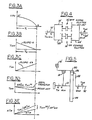
- Figure 1 is a schematic diagram of a gear set and clutch arrangement of an automatic transmission suited for control by the system according to this invention.
- Figure 2 is a graph showing the variation with time of engine speed, output torque and hydraulic pressure in the offgoing and oncoming function elements.
- Figures 3A-3E show the variation of engine speed, torque of the offgoing clutch, torque of the oncoming clutch, output torque and input torque during the clutch load transfer controlled by the method of this invention.
- Figure 4 is a schematic diagram showing the gear set of a multiple countershaft automatic transmission and the associated clutches whose selective engagement produces the various speed ratios.
- Figure 5 is a schematic diagram illustrating a planetary gear set and the friction elements whose selective operation produces the speed ratios.
- Referring first to Figure 1, the
crankshaft 10 of anengine 12 or other power source is adapted for connection by first andsecond clutches 14, 16 to first andsecond driveshafts -
Input shaft 18 is a sleeve shaft through whichinput shaft 20 extends. Support for the shaft is provided by bearings retained in recesses formed in the transmission case. - Shaft 18 has a first forward
speed ratio pinion 22 and a third-fifth forwardspeed ratio pinion 24 fixed to the shaft.Input shaft 20 has a fourth-sixth forward speed ratio pinion 26 and a second forward speed-reverse drive pinion 28 fixed to the shaft. - A
first countershaft 30 rotatably supported on the transmission casing parallel to the axis of the input shafts supports first, third and fourth forwardspeed ratio gears reverse gear 38, all of which are journalled on the surface of the countershaft. Located betweengears synchronizer clutch 40, whose hub is fixed to the countershaft and is adapted to drivably connectgears gear wheels gears synchronizer clutch 42, whose hub is fixed to countershaft 30 and is adapted to selectively drivably connectgears gear wheels - A
second countershaft 44 is rotatably supported on the transmission casing parallel to the axis of the input shafts. Journalled on the surface ofcountershaft 44 is a gear wheel 46 that includes reverse pinion 48 and a second speed gear 50. Also journalled oncountershaft 44 are afifth speed gear 52 and asixth speed gear 54. Located betweengears 50 and 54 is a third coupler or synchronizer clutch 56, whose hub is fixed tocountershaft 44 and is adapted to selectively drivably connectgears 50 and 54 to the countershaft by sliding the clutch sleeve into engagement with dog teeth carried on the gear wheels. A fourth coupler orsynchronizer clutch 58 has its hub fixed tocountershaft 44 and is adapted to selectively drivably connectgear 52 to the countershaft by engaging dog teeth formed on the gear wheel. A reverse idler pinion 59 is in continuous meshing engagement with second speed gear 50 andreverse gear 38. - Formed integrally with
countershaft 30 is an output gear 60, and formed integrally withcountershaft 44 is anoutput gear 62. The output gears are held in continuous meshing engagement with thedifferential input gear 64, which carriesbevel pinions 66, 68 that are continuously engaged withside bevel gears Output gear 64 turns the carrier on which the bevel gears are supported, and axle shafts 74, 76, which are fixed to the side bevel gears, are driven rotatably about their axes through operation of the differential mechanism. - The first forward speed ratio is produced when
clutch 14 is engaged, clutch 16 is disengaged,synchronizer clutch 58 is in its neutral position, the sleeve ofsynchronizer clutch 40 is moved rightward to the first speed ratio position, and the clutches ofsynchronizer clutches 42 and 56 are moved leftward to preselect the reverse and second speed ratios, respectively. With the transmission disposed in this way,crankshaft 10 is clutched to the first input shaft 13,pinion 22drives gear 32,countershaft 30 is driven throughsynchronizer clutch 40 and output gear 60 drives thedifferential ring gear 64. - A speed ratio change to the second gear ratio results after
friction clutch 14 is disengaged and clutch 16 is engaged. Thereafter,synchronizer 40 is shifted to the left thereby preselecting the third speed ratio, the sleeves ofsynchronizer clutches second input shaft 20, input pinion 28, gears 48 and 50, synchronizer clutch 56,countershaft 44,output gear 62,differential ring gear 64, the differential mechanism, and axle shafts 74, 76. - Therefore, the transmission is characterized by two possible torque paths, one associated with odd-numbered gear ratios, the other with even-numbered gear ratios, and each is activated via appropriate clutch-synchronizer combinations. The mechanism for transferring the load from the first or offgoing
clutch 14 to the second or oncoming clutch 16 while making a power-on upshift from the first speed ratio to the second speed ratio is described next with reference to Figure 2. In the following development, it is assumed that I is the rotating engine inertia about its axis; however, the results can be applied with minor modifications to more general cases, such as those where I includes also the rotating inertia of a torque converter turbine and other rotating components of the driveline located between the clutches and the engine. Further, in the following development, it is assumed that engine torque is held constant while the load is transferred from the first clutch to the second clutch, and the vehicle speed is assumed to be constant during the load transfer from the first clutch to the second clutch. - Referring now to Figure 2, a power-on upshift from the first to the second gear ratio results when first the pressure in the offgoing
clutch 14 is decreased at 78 until the slip across that clutch reaches a prescribed value corresponding to an increase in engine speed of ΔNe revolutions per minute at point G′. This amount of slip is then maintained by controlling, through operation of the closed loop electronic control circuit, the pressure in the offgoingclutch 14. - The present invention pertains to the torque phase of the clutch-to-clutch load transfer that occurs between times tD and tE hereinafter referred to as the clutch-to-clutch torque (CTCT) transfer. In the prior art the CTCT transfer operates to change the engine torque between the two clutches without altering the engine speed, thereby creating the aforementioned inescapable output torque reduction or depression indicated by the dashed line in the graph of the output torque of Figure 2. According to the method of this invention, at time tD, engine inertia or its equivalent is used to fill as much of the output torque depression as is deemed necessary. In this way, contrary to common belief, at the end of the CTCT transfer at time tE, any level of output torque, such as the range between points F-F′ can be realized at the conclusion of the torque phase of the gear ratio change.
- The clutch load transfer period lasts for t seconds and extends over the period from the occurrence of maximum engine speed produced by slipping the offgoing clutch 14 at point G′ to the zero slip point G. The conclusion of CTCT transfer can also be identified by the occurrence of zero pressure in the offgoing clutch 14 or of a predetermined level of stroking pressure within the offgoing clutch, as represented by point H. Ideally, points G and H should substantially coincide, and the mathematical relationships that ensure this are developed subsequently for a wide class of transmissions, such as those having planetary gear sets, as illustrated in Figure 5, and multiple countershaft gear sets, as illustrated in Figures 1 and 4.
- Hydraulic pressure in
clutches 14 and 16, and the speeds of the various shafts of the driveline are determined from the output of suitable transducers that produce an electrical signal representing the respective variable. First, by controlling the slip of clutch 14, engine speed increases by the amount ΔNe desired to be produced at the output torque level at the beginning of the CTCT transfer. Then at point I, a maximum offgoing clutch pressure slope is chosen. Using this information, transfer constant C₁ is calculated off-line and stored in a memory accessible to a microprocessor onboard the motor vehicle. During the clutch load transfer at time tD, when the desired slip across the offgoing clutch is present, the pressure of the offgoing clutch, point I, is measured and the offgoing clutch pressure slope kp is calculated. The clutch load transfer during the torque phase of the gear ratio change occurs over the period from tD to tE by controlling the linear increase of the pressure of the oncoming clutch 16, represented by line 80 and the linear decrease of pressure in the offgoing clutch 14, represented byline 82. The slopes of the clutch pressure ramps are determined according to the mathematical development that follows. Finally, at time tE when the torque phase of the gear shift is completed, the remaining portion of the gear shift is controlled through the operation of a closed-loop control. After time tE, the gearshift would proceed with closed loop speed ratio control over the oncoming clutch pressure until time tF, the conclusion of the ratio change. - If pressure transducers are unavailable to produce signals representing the pressure in
clutches 14 and 16, the control method of this invention can be approximated by using the closed loop speed ratio control. For example at time tD, the pressure in clutch 16 is rising according to the slope of line 80; concurrently a predetermined speed ratio and slip are being maintained using a closed loop PID control. Because the pressure ramp of ongoing clutch 16 acts as a disturbance to the single integrator or PID controller, the offgoing clutch pressure will fall; concurrently, due to the unavoidable steady-state error, the clutch slip and engine speed will decrease. This action approximates the ideal curve G′-G of Figure 2. - The method according to this invention can be applied equally well for CTCT transfer during power-on downshifts. In this instance, however, the engine speed is held below the synchronous speed by ΔNe revolutions per minute and the ideal CTCT transfer can be achieved without output torque spikes using the inertia of the engine or a comparable rotating inertia.
- Throughout the following development, the power-on upshift from the first speed ratio to the second speed ratio is described. With reference to Figure 3, as the pressure of the offgoing clutch reduces the slip across the offgoing clutch, i. e., the difference in speed between the input member of the clutch and its output member increases, thereby removing load from the engine and increasing the speed of the engine shaft by an amount ΔNe above the synchronous engine speed corresponding to the current operating speed ratio. The rise in engine speed occurs over a period preceding time tD. Thereafter, the torque transmitted by the offgoing clutch decreases and the torque carried by the oncoming clutch decreases in accordance with the following relationships:
Toff (t) = -kt + Toff (0) (1)
Ton (t) = s′ · k · t (2)
where Toff and Ton are the torques ofclutches 14 and 16, respectively, k is the time rate of change of the offgoing clutch torque, t is time and s′ is a variable whose magnitude is in the range 1 ≦ s′ ≦ s. During the torque transfer, the transmission output torque is given by:

- Figure 3D is a graph of the variation with time of the transmission output torque for the ideal clutch load transfer and for the prior art clutch load transfer. Now if

Tout = SR· Toff (0) (5)
- However, for the conventional automatic transmission, the output torque at the end of the torque phase of the clutch load transfer reduces to
Tout = SR· Toff (0) (6)
along the dashed line in Figure 3D. Therefore, by varying s′ between 1 and s, any output torque between the ideal clutch load transfer, represented by equation (5), and the conventional or prior art value, represented by equation (6), can be produced. This ideal clutch load transfer is possible because of the change in engine momentum
I .. ΔNe = t₁ ΔTin(t) · dt = t₁ · ΔTin (t₁)/2 (7)
where I is the rotational inertia of the engine or of other rotating components in the driveline upstream of the transmission input shaft and ΔTin is the time rate of change of engine load torque due to the CTCT transfer. It can be shown that

- Combining equations (7) and (8) and noting that for optimal clutch load transfer t₁ = t₂ = t, the time to complete the torque phase of the gear shift is given by:

- The time rate of change of torque transmitted by the offgoing clutch at time t(0) is k = Toff(0)/t. Substituting from equation (9), that time rate or slope becomes


- The CTCT transfer method according to this invention therefore begins by predetermining the allowable increase in engine speed that results from slipping the offgoing clutch and predetermining the value for s′. The constant c₁ is calculated from equation (11) using the values of certain predetermined parameters, engine inertia and the speed ratios of the gear set upstream of the respective clutches. Then, after the slip across the offgoing clutch increases sufficiently to produce the predetermined increase in engine speed, the offgoing clutch torque or pressure slope is calculated from equation (10a), where the torque of the offgoing clutch at t(0) is calculated from either engine torque or offgoing clutch pressure. Then, the two clutch torque ramps, whose slopes correspond to -k and +ks′, are supplied to the offgoing clutch and oncoming clutch, respectively. The change in engine speed during the power-on upshift or torque across the offgoing clutch, and the clutch pressure in the offgoing clutch are monitored continuously during the gear shift. If either the change in engine speed becomes equal to zero, i.e., engine speed returns to the synchronous speed corresponding to the initial speed ratio at the beginning of the gear shift, or the torque across the offgoing clutch becomes zero, then the offgoing clutch is vented to atmosphere or its pressure is reduced substantially to a value that permits that clutch to be barely stroked. Then the pressure of the oncoming clutch is controlled through operation of the closed loop control.
- In the gear set arrangement of Figure 1, the gear set speed ratio upstream of offgoing clutch 14 and oncoming clutch 16 is equal to unity, but the gear set speed ratio downstream from these clutches are positive non-equal integrals or mixed numbers. Ideally, ΔNe is approximately 150 rpm, and s′, stated in terms of s, which is the gear set speed ratio downstream of the offgoing clutch divided by the gear set speed ratio downstream of the ongoing clutch, is

- The corresponding gear set speed ratios for the arrangement of Figure 5 are:


sun gear 84 and r₂ is the radius of theplanetary pinions 86, which are rotatably supported oncarrier 88 and are engaged continuously withring gear 90. The oncoming clutch 14 selectively connectsring gear 90 to theengine crankshaft 10; the offgoing brake 16′ selectively connects the ring gear to the transmission casing, thereby preventing rotation of the ring gear. - The corresponding gear set speed ratios of the gear arrangement shown in Figure 4 depend upon the corresponding sizes of the meshing gears.
- The slopes of the friction element pressures are related linearly to k, the slope of the offgoing clutch torque, the relationship:
kp = k/G (17)
where Kp is the slope of the clutch pressure ramp and G is the clutch gain.
Claims (3)
increasing the engine speed to a first predetermined speed by increasing the slip across the first friction element to a first predetermined slip;
calculating the CTCT transfer constant c₁ from the relationship;
calculating the slope kp of the pressure ramp for the first friction element from the relationship

determining the rotational inertia I of the engine and other rotating components of the drivetrain upstream of the transmisssion gearset, the gearset speed ratios downstream of the offgoing friction element

increasing the engine speed to a first predetermined speed by increasing the slip across the first friction element to a first predetermined slip;
calculating the CTCT transfer constant c₁ from the relationship

calculating the slope Kp of the pressure ramp for the first friction element from the relationship

determining the rotational inertia I of the engine and other rotating components of the drivetrain upstream of the transmisssion gearset, the gearset speed ratios downstream of the offgoing friction element


calculating the time rate of change of torque of the offgoing friction element from the relationship k=c₁ T
increasing the pressure of the second friction element at a time rate substantially equal to k(s′);
concurrently decreasing the pressure of the first friction element at a time rate substantially equal to k; and
reducing the pressure of the first friction element when the engine speed at the beginning of the exchange of load from the first friction element to the second friction element and the engine speed that corresponds to the current speed ratio and the vehicle speed becomes substantially equal.
Applications Claiming Priority (2)
| Application Number | Priority Date | Filing Date | Title |
|---|---|---|---|
| US44094 | 1987-04-30 | ||
| US07/044,094 US4790418A (en) | 1987-04-30 | 1987-04-30 | Transmission clutch loop transfer control |
Publications (3)
| Publication Number | Publication Date |
|---|---|
| EP0288779A2 true EP0288779A2 (en) | 1988-11-02 |
| EP0288779A3 EP0288779A3 (en) | 1989-05-03 |
| EP0288779B1 EP0288779B1 (en) | 1991-11-21 |
Family
ID=21930501
Family Applications (1)
| Application Number | Title | Priority Date | Filing Date |
|---|---|---|---|
| EP88105325A Expired - Lifetime EP0288779B1 (en) | 1987-04-30 | 1988-04-01 | Transmission clutch loop transfer control |
Country Status (4)
| Country | Link |
|---|---|
| US (1) | US4790418A (en) |
| EP (1) | EP0288779B1 (en) |
| JP (1) | JPS63297849A (en) |
| DE (1) | DE3866275D1 (en) |
Cited By (30)
| Publication number | Priority date | Publication date | Assignee | Title |
|---|---|---|---|---|
| EP0435376A2 (en) * | 1989-12-26 | 1991-07-03 | General Motors Corporation | Method of controlling gear change in an automatic transmission |
| EP0525853A2 (en) * | 1991-07-31 | 1993-02-03 | Saturn Corporation | A method of operation for an automatic transmission |
| WO1994012814A1 (en) * | 1992-12-03 | 1994-06-09 | Zf Friedrichshafen Aktiengesellschaft | Process for controlling and regulating the load take-up in an automatic gearbox |
| EP0627336A2 (en) * | 1993-06-03 | 1994-12-07 | Aisin Aw Co., Ltd. | Shift control system for automatic transmissions |
| EP0753688A1 (en) * | 1994-03-31 | 1997-01-15 | Komatsu Ltd. | Method of power transmission in mechanical/hydraulic type transmission |
| EP0825058A3 (en) * | 1996-08-08 | 1998-09-09 | Volkswagen Aktiengesellschaft | Method for gear shift of a doulble clutch gearbox and doulble clutch transmission with synchronizing device |
| WO1998054490A1 (en) * | 1997-05-31 | 1998-12-03 | Zf Friedrichshafen Ag | Increased automatic gear box spontaneity |
| DE19821164A1 (en) * | 1998-05-12 | 1999-11-18 | Volkswagen Ag | Double clutch gearing for automobile use |
| DE19923185A1 (en) * | 1999-05-20 | 2000-12-07 | Daimler Chrysler Ag | Variable speed transmission for motor vehicles has second output shaft parallel to first and with axial spacing from intermediate shafts or differential deviating from that of first output shaft |
| GB2352278A (en) * | 1999-05-11 | 2001-01-24 | Ford Global Tech Inc | A method of improving shift feel in an automatic transmission |
| DE19944879A1 (en) * | 1999-09-18 | 2001-03-22 | Volkswagen Ag | Double clutch |
| EP1106876A2 (en) | 1999-12-09 | 2001-06-13 | Honda Giken Kogyo Kabushiki Kaisha | Control system for automatic vehicle transmissions |
| DE10015336A1 (en) * | 2000-03-28 | 2001-10-04 | Volkswagen Ag | Dual clutch gearbox has elements arranged so that for certain engaged gear drive train consists of first drive shaft, parallel shaft, second input shaft and output shaft |
| WO2002055910A1 (en) * | 2001-01-12 | 2002-07-18 | Zf Sachs Ag | Method for the operation of a multiple clutching device and a power shift transmission |
| EP1367294A3 (en) * | 1998-12-24 | 2004-02-04 | DaimlerChrysler AG | Toothed speed-changing gearing with two parallel transmission paths |
| FR2852651A1 (en) * | 2003-03-17 | 2004-09-24 | Renault Sa | Gear box for motor vehicle, has primary solid shaft and concentric primary hollow shaft holding fixed pinions, and secondary shafts holding idle pinions, where fixed pinions are engaged with respective idle pinions |
| FR2861447A1 (en) * | 2003-10-22 | 2005-04-29 | Renault Sa | Gearbox for motor vehicles driving system, has jaw clutching to couple set of pinions on their shafts for selection of pinions, where pinions for first gear and reverse gear are driven by respective primary shafts |
| EP1245863A3 (en) * | 2001-03-27 | 2005-09-14 | C.R.F. Società Consortile per Azioni | A motor-vehicle gearbox |
| WO2005093289A1 (en) * | 2004-03-17 | 2005-10-06 | Daimlerchrysler Ag | Double-clutch gearbox |
| WO2006056325A2 (en) * | 2004-11-23 | 2006-06-01 | Getrag Getriebe- Und Zahnradfabrik Hermann Hagenmeyer Gmbh & Cie Kg | Stepped transmission for a motor vehicle |
| WO2006056326A1 (en) * | 2004-11-23 | 2006-06-01 | Getrag Getriebe-Und Zahnradfabrik Hermann Hagenmeyer Gmbh & Cie Kg | Actuator arrangement with selector drum for a double-clutch gearbox |
| FR2880089A1 (en) * | 2004-12-29 | 2006-06-30 | Renault Sas | Gearbox for motor vehicle, has filled primary shaft transmitting engine torque for forward gear ratio and hollow primary shaft transmitting engine torque for reverse gear ratio, where shafts are alternatively connected to engine shaft |
| US7258032B2 (en) | 2003-12-10 | 2007-08-21 | Hyundai Motor Company | Double clutch transmission |
| WO2009121568A1 (en) * | 2008-03-31 | 2009-10-08 | Gm Global Technology Operations, Inc. | Double-clutch transmission for vehicles |
| EP1445516A3 (en) * | 2003-02-05 | 2010-02-24 | Nissan Motor Company, Limited | Multistage automatic transmission |
| CN102444696A (en) * | 2010-09-30 | 2012-05-09 | C.R.F.阿西安尼顾问公司 | Gear change device for a motor-vehicle |
| DE102006022183B4 (en) * | 2006-05-12 | 2015-04-09 | Daimler Ag | Double clutch |
| CN113007239A (en) * | 2021-04-28 | 2021-06-22 | 一汽解放汽车有限公司 | AMT clutch friction point self-learning method and system and vehicle |
| US11076616B2 (en) | 2013-10-24 | 2021-08-03 | Evonik Operations Gmbh | L-amino acid-containing feedstuff additive |
| US11723384B2 (en) | 2013-10-24 | 2023-08-15 | Evonik Operations Gmbh | L-amino acid-containing feedstuff additive |
Families Citing this family (90)
| Publication number | Priority date | Publication date | Assignee | Title |
|---|---|---|---|---|
| US4984483A (en) * | 1987-04-15 | 1991-01-15 | Mitsubishi Jidosha Kogyo Kabushiki Kaisha | Control system for an automatic transmission of a motor vehicle |
| US4855914A (en) * | 1987-11-27 | 1989-08-08 | Davis Roy I | Computer controlled synchronous shifting of an automatic transmission |
| US4982620A (en) * | 1988-04-29 | 1991-01-08 | Chrysler Corporation | Method of learning for adaptively controlling an electronic automatic transmission system |
| US5211080A (en) * | 1988-04-29 | 1993-05-18 | Chrysler Corporation | Method of shift control during a coastdown shift for an electronic automatic transmission system |
| JPH07113408B2 (en) * | 1989-02-28 | 1995-12-06 | 日産自動車株式会社 | Hydraulic control device for automatic transmission |
| US5014573A (en) * | 1989-12-11 | 1991-05-14 | General Motors Corporation | Double transition upshift control in an automatic transmission |
| US5058460A (en) * | 1990-01-11 | 1991-10-22 | General Motors Corporation | Clutch-to-clutch control in an automatic transmission |
| US4989477A (en) * | 1990-01-11 | 1991-02-05 | General Motors Corporation | Double transition closed throttle downshift control in an automatic transmissions |
| JP2822527B2 (en) * | 1990-01-19 | 1998-11-11 | トヨタ自動車株式会社 | Automatic transmission for vehicles |
| DE4003866A1 (en) * | 1990-02-09 | 1991-08-14 | Man Nutzfahrzeuge Ag | CONTROL FOR THE CLUTCH OF A TRANSMISSION IN A MOTOR VEHICLE |
| EP0517705B1 (en) * | 1990-03-01 | 1994-07-06 | Volkswagen Aktiengesellschaft | Process for changing a step-by-step variable gear |
| US5188005A (en) * | 1990-09-14 | 1993-02-23 | Ford Motor Company | Method and system for improving smoothness of shifts in an automatic transmission |
| US5121820A (en) * | 1990-12-24 | 1992-06-16 | Ford Motor Company | Feedforward control for automatic transmission torque converter bypass clutch slip |
| US5123302A (en) * | 1990-12-24 | 1992-06-23 | Ford Motor Company | Automatic transmission gearshift control having feedforward response of clutch and its hydraulic actuation |
| US5251132A (en) * | 1991-02-05 | 1993-10-05 | Ford New Holland, Inc. | Clutch pressure control based on output shaft speed |
| US5304102A (en) * | 1991-02-21 | 1994-04-19 | Nissan Motor Co., Ltd. | Control for shift in automatic transmission |
| JP2616603B2 (en) * | 1991-05-23 | 1997-06-04 | 日産自動車株式会社 | Transmission control device for automatic transmission |
| US5303794A (en) * | 1991-12-17 | 1994-04-19 | Ford Motor Company | Wheel spin control using electronically controlled clutches and engine controls |
| JPH05180316A (en) * | 1992-01-07 | 1993-07-20 | Nissan Motor Co Ltd | Transmission control device for automatic transmission |
| JP2850615B2 (en) * | 1992-01-07 | 1999-01-27 | 日産自動車株式会社 | Transmission control device for automatic transmission |
| JPH05306752A (en) * | 1992-04-28 | 1993-11-19 | Jatco Corp | Controller for automatic transmission |
| JP3283323B2 (en) * | 1993-03-26 | 2002-05-20 | マツダ株式会社 | Hydraulic control device for shifting of automatic transmission |
| US5456647A (en) * | 1993-05-24 | 1995-10-10 | Chrysler Corporation | End of line volume learn sequence of friction element fill volumes for automatic transmission |
| JPH0771580A (en) * | 1993-09-01 | 1995-03-17 | Honda Motor Co Ltd | Control device of hydraulic actuation type transmission for vehicle |
| US5581479A (en) * | 1993-10-15 | 1996-12-03 | Image Telecommunications Corp. | Information service control point, which uses different types of storage devices, which retrieves information as blocks of data, and which uses a trunk processor for transmitting information |
| JP2977015B2 (en) * | 1994-12-28 | 1999-11-10 | 本田技研工業株式会社 | Hydraulic control device for hydraulically operated transmission for vehicle |
| US5568748A (en) * | 1995-01-11 | 1996-10-29 | Caterpillar Inc. | Method for modifying the shiftpoints of an automatic transmission |
| US5527238A (en) * | 1995-04-10 | 1996-06-18 | Ford Motor Company | Automatic transmission bypass clutch slip control using nonlinear nverse dynamics |
| US5551930A (en) * | 1995-04-13 | 1996-09-03 | Caterpillar Inc. | Adaptive control method for an automatic transmission |
| US5580332A (en) * | 1995-04-13 | 1996-12-03 | Caterpillar Inc. | Method for determining the fill time of a transmission clutch |
| US5655993A (en) * | 1995-04-17 | 1997-08-12 | Honda Giken Kogyo Kabushiki Kaisha | Shift control apparatus for an automatic transmission |
| US5630096A (en) * | 1995-05-10 | 1997-05-13 | Microunity Systems Engineering, Inc. | Controller for a synchronous DRAM that maximizes throughput by allowing memory requests and commands to be issued out of order |
| JP3536537B2 (en) * | 1996-06-28 | 2004-06-14 | トヨタ自動車株式会社 | Shift control device for automatic transmission for vehicle |
| DE69738010T2 (en) * | 1996-09-25 | 2008-04-30 | Honda Giken Kogyo K.K. | Control device for hydraulically operated vehicle |
| US5806370A (en) * | 1996-11-13 | 1998-09-15 | Caterpillar Inc. | Method for modifying the shiftpoints of an automatic transmission |
| JP3744192B2 (en) * | 1998-03-17 | 2006-02-08 | アイシン・エィ・ダブリュ株式会社 | Control device for automatic transmission |
| US6115661A (en) * | 1998-04-09 | 2000-09-05 | Caterpillar Inc. | End-of-fill detector for a fluid actuated clutch |
| US5950789A (en) * | 1998-04-27 | 1999-09-14 | Caterpillar Inc. | End of fill detector for a fluid actuated clutch |
| EP1132660B1 (en) * | 1998-11-16 | 2007-09-12 | Yanmar Co., Ltd. | Method of controlling hydraulic pressure in speed change mechanism having hydraulic clutch |
| US6350213B1 (en) | 2000-06-29 | 2002-02-26 | Borgwarner Inc. | Direct computer controlled electro hydraulic device for multi-speed transmission friction element control |
| US6463821B1 (en) | 2001-06-29 | 2002-10-15 | Daimlerchrysler Corporation | Method of controlling a transmission having a dual clutch system |
| US6754574B2 (en) * | 2002-01-24 | 2004-06-22 | Toyota Jidosha Kabushiki Kaisha | Controller for automatic transmission |
| EP1353095A1 (en) * | 2002-04-10 | 2003-10-15 | Van Doorne's Transmissie B.V. | Control method for an automatic transmission |
| US7197662B2 (en) * | 2002-10-31 | 2007-03-27 | Ring Technology Enterprises, Llc | Methods and systems for a storage system |
| US6879526B2 (en) * | 2002-10-31 | 2005-04-12 | Ring Technology Enterprises Llc | Methods and apparatus for improved memory access |
| US7415565B2 (en) | 2002-10-31 | 2008-08-19 | Ring Technology Enterprises, Llc | Methods and systems for a storage system with a program-controlled switch for routing data |
| US7707351B2 (en) * | 2002-10-31 | 2010-04-27 | Ring Technology Enterprises Of Texas, Llc | Methods and systems for an identifier-based memory section |
| US6832978B2 (en) * | 2003-02-21 | 2004-12-21 | Borgwarner, Inc. | Method of controlling a dual clutch transmission |
| US6869382B2 (en) | 2003-05-07 | 2005-03-22 | Daimlerchrysler Corporation | Double-downshift gear strategy for a dual clutch automatic transmission |
| DE10324095A1 (en) * | 2003-05-27 | 2004-12-16 | Deere & Company, Moline | Gear arrangement and method for operating a gear arrangement |
| FR2847637B1 (en) * | 2003-07-28 | 2005-05-06 | Michel Alain Leon Marchisseau | SYNCHRONIZATION MODULE WITH TORQUE FOR GEARBOX |
| EP1507103B1 (en) * | 2003-08-14 | 2006-04-05 | Getrag Ford Transmissions GmbH | Method for shifting dual clutches |
| US6991584B2 (en) * | 2003-11-12 | 2006-01-31 | Ford Global Technologies, Llc | Control of powertrain smoothness using output torque sensing and input torque control |
| ATE549550T1 (en) * | 2004-02-13 | 2012-03-15 | Schaeffler Technologies Ag | METHOD AND DEVICE FOR CONTROLLING A GEAR CHANGE IN A PARALLEL SHIFTING TRANSMISSION OF A VEHICLE |
| ATE423921T1 (en) * | 2004-04-06 | 2009-03-15 | Luk Lamellen & Kupplungsbau | METHOD FOR CONTROLLING THE CLUTCH TORQUE OF A CLUTCH OF AN AUTOMATED TRANSMISSION AND A DEVICE FOR CARRYING OUT THE METHOD |
| US7326149B2 (en) * | 2004-11-05 | 2008-02-05 | Ford Global Technologies, Llc | Converterless transmission shift control system |
| US7384374B2 (en) * | 2005-12-16 | 2008-06-10 | Ford Global Technologies, Llc | Tip-in/tip-out gear shift control for a powershift automatic transmission |
| JP4828929B2 (en) * | 2005-12-19 | 2011-11-30 | 日立オートモティブシステムズ株式会社 | Automatic transmission control device, control method, and automatic transmission |
| JP4533859B2 (en) * | 2006-03-09 | 2010-09-01 | ジヤトコ株式会社 | Shift control device and shift control method for twin clutch transmission for vehicle |
| US7752934B2 (en) * | 2007-02-20 | 2010-07-13 | Gm Global Technology Operations, Inc. | Multi speed transmission having a countershaft gearing arrangement |
| US7703346B2 (en) * | 2007-02-22 | 2010-04-27 | Gm Global Technology Operations, Inc. | Multi-speed transmission with countershaft gearing |
| US7499784B2 (en) * | 2007-04-09 | 2009-03-03 | General Motors Corporation | Method of selecting a transmission shift schedule |
| CN102047003A (en) * | 2008-03-31 | 2011-05-04 | 通用汽车环球科技运作公司 | Double-clutch transmission for vehicles |
| CN102047002A (en) * | 2008-03-31 | 2011-05-04 | 通用汽车环球科技运作公司 | Double-clutch transmission for vehicles |
| EP2370286B1 (en) * | 2008-12-09 | 2013-09-18 | Borgwarner Inc. | Automatic transmission for a hybrid vehicle |
| JP5238958B2 (en) | 2009-02-24 | 2013-07-17 | アイシン・エーアイ株式会社 | Dual clutch automatic transmission |
| WO2011008428A2 (en) | 2009-06-29 | 2011-01-20 | Borgwarner Inc. | Hydraulic valve for use in a control module of an automatic transmission |
| US8328688B2 (en) | 2010-01-25 | 2012-12-11 | Ford Global Technologies, Llc | Ratio shift control system and method for a multiple-ratio automatic transmission |
| US8337361B2 (en) | 2010-01-25 | 2012-12-25 | Ford Global Technologies, Llc | Multiple-ratio automatic transmission control method and system for ratio upshifts |
| FR2970054B1 (en) * | 2011-01-03 | 2013-01-18 | Renault Sa | METHOD FOR CONTROLLING AN AUTOMATIC SPEED BOX |
| DE102011000957A1 (en) * | 2011-02-28 | 2012-08-30 | Dr. Ing. H.C. F. Porsche Aktiengesellschaft | Method for switching a semi-automatic powershift transmission |
| US8821344B2 (en) * | 2011-06-08 | 2014-09-02 | Ford Global Technologies, Llc | Controlling a transmission skip change upshift |
| US8775044B2 (en) | 2011-06-08 | 2014-07-08 | Ford Global Technologies, Llc | Clutch torque trajectory correction to provide torque hole filling during a ratio upshift |
| US8636613B2 (en) | 2011-12-19 | 2014-01-28 | Ford Global Technologies, Llc | Clutch torque trajectory correction to provide torque hole filling during a ratio upshift |
| US8744705B2 (en) * | 2012-03-15 | 2014-06-03 | GM Global Technology Operations LLC | System and method for determining clutch gains in a transmission during a power downshift |
| US8808141B2 (en) | 2012-05-07 | 2014-08-19 | Ford Global Technologies, Llc | Torque hole filling in a hybrid vehicle during automatic transmission shifting |
| US8827060B2 (en) | 2012-09-13 | 2014-09-09 | Ford Global Technologies, Llc | Transmission and method of controlling clutch during ratio change |
| US8938340B2 (en) | 2013-03-13 | 2015-01-20 | Ford Global Technologies, Llc | Automatic transmission shift control based on clutch torque capacity detection using calculated transmission input torque |
| JP6278332B2 (en) * | 2013-04-22 | 2018-02-14 | スズキ株式会社 | Transmission control device |
| US9512889B2 (en) * | 2013-04-30 | 2016-12-06 | Ford Global Technologies, Llc | Control of a transmission friction element using an adaptive transfer function |
| US9933069B2 (en) | 2013-04-30 | 2018-04-03 | Ford Global Technologies, Llc | Dynamic compensation for clutch control during shift |
| US9829411B2 (en) | 2013-04-30 | 2017-11-28 | Ford Global Technologies, Llc | Method of calibrating a wet clutch for generating transfer functions on a test bench |
| US8965649B1 (en) * | 2013-08-08 | 2015-02-24 | GM Global Technology Operations LLC | Transmission with power downshift anticipation logic |
| KR101558688B1 (en) * | 2013-12-13 | 2015-10-07 | 현대자동차주식회사 | Transmission for vehicle |
| US9404571B2 (en) | 2014-06-04 | 2016-08-02 | Ford Global Technologies, Llc | Controlling an automatic transmission |
| GB2547650B (en) * | 2016-02-23 | 2022-01-12 | Chongqing Changan Automobile Co Ltd | A dual clutch transmission |
| US9951827B2 (en) | 2016-03-11 | 2018-04-24 | Ford Global Technologies, Llc | Method to identify automatic transmission lubrication oil flow rates corresponding to a running vehicle without direct oil flow measurements |
| JP6673261B2 (en) * | 2017-02-24 | 2020-03-25 | トヨタ自動車株式会社 | Vehicle speed change control device |
| US10399557B2 (en) | 2017-11-10 | 2019-09-03 | Ford Global Technologies, Llc | Engine/motor torque control for torque hole filling in a hybrid vehicle during automatic transmission shifting |
| CN110375011B (en) * | 2019-07-24 | 2020-10-02 | 合肥工业大学 | Control method for avoiding power-shifting transmission gear-up power circulation |
Citations (4)
| Publication number | Priority date | Publication date | Assignee | Title |
|---|---|---|---|---|
| DE2758651A1 (en) * | 1977-01-03 | 1978-07-13 | Borg Warner | ELECTRONIC CONTROL FOR AN AUTOMATIC MANUAL GEARBOX |
| GB1586923A (en) * | 1977-02-14 | 1981-03-25 | Toyota Motor Co Ltd | Oil presure control means for an automatic transmission |
| GB2117462A (en) * | 1982-02-27 | 1983-10-12 | Toyota Motor Co Ltd | Transmission control method and transmission control device providing snappy downshifting |
| US4468987A (en) * | 1980-05-09 | 1984-09-04 | Ab Volvo | Control system for multi-ratio gearing |
Family Cites Families (4)
| Publication number | Priority date | Publication date | Assignee | Title |
|---|---|---|---|---|
| US3956947A (en) * | 1974-06-14 | 1976-05-18 | Chrysler Corporation | Adaptive control system for automatic transmission |
| DE2913824A1 (en) * | 1979-04-06 | 1980-10-16 | Bosch Gmbh Robert | METHOD FOR DETERMINING THE FREEWHEEL POINT AND GEARBOX WITH MEASURING DEVICE |
| US4527678A (en) * | 1982-12-27 | 1985-07-09 | Ford Motor Company | Transmission clutch control system and method |
| JPS61241558A (en) * | 1985-04-18 | 1986-10-27 | Toyota Motor Corp | Method of controlling speed change of automatic transmission for vehicle |
-
1987
- 1987-04-30 US US07/044,094 patent/US4790418A/en not_active Expired - Fee Related
-
1988
- 1988-04-01 DE DE8888105325T patent/DE3866275D1/en not_active Expired - Lifetime
- 1988-04-01 EP EP88105325A patent/EP0288779B1/en not_active Expired - Lifetime
- 1988-04-28 JP JP63107446A patent/JPS63297849A/en active Pending
Patent Citations (4)
| Publication number | Priority date | Publication date | Assignee | Title |
|---|---|---|---|---|
| DE2758651A1 (en) * | 1977-01-03 | 1978-07-13 | Borg Warner | ELECTRONIC CONTROL FOR AN AUTOMATIC MANUAL GEARBOX |
| GB1586923A (en) * | 1977-02-14 | 1981-03-25 | Toyota Motor Co Ltd | Oil presure control means for an automatic transmission |
| US4468987A (en) * | 1980-05-09 | 1984-09-04 | Ab Volvo | Control system for multi-ratio gearing |
| GB2117462A (en) * | 1982-02-27 | 1983-10-12 | Toyota Motor Co Ltd | Transmission control method and transmission control device providing snappy downshifting |
Cited By (54)
| Publication number | Priority date | Publication date | Assignee | Title |
|---|---|---|---|---|
| EP0435376A2 (en) * | 1989-12-26 | 1991-07-03 | General Motors Corporation | Method of controlling gear change in an automatic transmission |
| EP0435376A3 (en) * | 1989-12-26 | 1993-03-03 | General Motors Corporation | Method of controlling gear change in an automatic transmission |
| EP0525853A2 (en) * | 1991-07-31 | 1993-02-03 | Saturn Corporation | A method of operation for an automatic transmission |
| EP0525853A3 (en) * | 1991-07-31 | 1994-03-02 | Saturn Corp | |
| US5609068A (en) * | 1992-12-03 | 1997-03-11 | Zf Friedrichshafen Ab | Process for controlling and regulating the load take-up in an automatic gearbox |
| WO1994012814A1 (en) * | 1992-12-03 | 1994-06-09 | Zf Friedrichshafen Aktiengesellschaft | Process for controlling and regulating the load take-up in an automatic gearbox |
| EP0627336A2 (en) * | 1993-06-03 | 1994-12-07 | Aisin Aw Co., Ltd. | Shift control system for automatic transmissions |
| EP0627336A3 (en) * | 1993-06-03 | 1996-05-08 | Aisin Aw Co | Shift control system for automatic transmissions. |
| US5583768A (en) * | 1993-06-03 | 1996-12-10 | Aisin Aw Co., Ltd. | Shift control system for preventing engine racing |
| EP0753688A1 (en) * | 1994-03-31 | 1997-01-15 | Komatsu Ltd. | Method of power transmission in mechanical/hydraulic type transmission |
| EP0753688A4 (en) * | 1994-03-31 | 1998-09-16 | Komatsu Mfg Co Ltd | Method of power transmission in mechanical/hydraulic type transmission |
| EP0825058A3 (en) * | 1996-08-08 | 1998-09-09 | Volkswagen Aktiengesellschaft | Method for gear shift of a doulble clutch gearbox and doulble clutch transmission with synchronizing device |
| US5890392A (en) * | 1996-08-08 | 1999-04-06 | Volkswagen Ag | Method for shifting a twin-clutch transmission and twin-clutch transmission arrangement |
| WO1998054490A1 (en) * | 1997-05-31 | 1998-12-03 | Zf Friedrichshafen Ag | Increased automatic gear box spontaneity |
| DE19821164A1 (en) * | 1998-05-12 | 1999-11-18 | Volkswagen Ag | Double clutch gearing for automobile use |
| DE19821164B4 (en) * | 1998-05-12 | 2008-04-17 | Volkswagen Ag | Double clutch |
| EP1367293A3 (en) * | 1998-12-24 | 2004-02-04 | DaimlerChrysler AG | Toothed speed-changing gearing with two parallel transmission paths |
| EP1367294A3 (en) * | 1998-12-24 | 2004-02-04 | DaimlerChrysler AG | Toothed speed-changing gearing with two parallel transmission paths |
| GB2352278B (en) * | 1999-05-11 | 2003-11-05 | Ford Global Tech Inc | Automatic transmission |
| GB2352278A (en) * | 1999-05-11 | 2001-01-24 | Ford Global Tech Inc | A method of improving shift feel in an automatic transmission |
| DE19923185A1 (en) * | 1999-05-20 | 2000-12-07 | Daimler Chrysler Ag | Variable speed transmission for motor vehicles has second output shaft parallel to first and with axial spacing from intermediate shafts or differential deviating from that of first output shaft |
| DE19944879B4 (en) * | 1999-09-18 | 2010-12-30 | Volkswagen Ag | Double clutch |
| DE19944879A1 (en) * | 1999-09-18 | 2001-03-22 | Volkswagen Ag | Double clutch |
| EP1106876A2 (en) | 1999-12-09 | 2001-06-13 | Honda Giken Kogyo Kabushiki Kaisha | Control system for automatic vehicle transmissions |
| EP1106876A3 (en) * | 1999-12-09 | 2006-08-02 | Honda Giken Kogyo Kabushiki Kaisha | Control system for automatic vehicle transmissions |
| DE10015336A1 (en) * | 2000-03-28 | 2001-10-04 | Volkswagen Ag | Dual clutch gearbox has elements arranged so that for certain engaged gear drive train consists of first drive shaft, parallel shaft, second input shaft and output shaft |
| WO2002055910A1 (en) * | 2001-01-12 | 2002-07-18 | Zf Sachs Ag | Method for the operation of a multiple clutching device and a power shift transmission |
| EP1245863A3 (en) * | 2001-03-27 | 2005-09-14 | C.R.F. Società Consortile per Azioni | A motor-vehicle gearbox |
| EP1445516A3 (en) * | 2003-02-05 | 2010-02-24 | Nissan Motor Company, Limited | Multistage automatic transmission |
| EP1471282A1 (en) * | 2003-03-17 | 2004-10-27 | Renault s.a.s. | Compact transmission with two clutches |
| FR2852651A1 (en) * | 2003-03-17 | 2004-09-24 | Renault Sa | Gear box for motor vehicle, has primary solid shaft and concentric primary hollow shaft holding fixed pinions, and secondary shafts holding idle pinions, where fixed pinions are engaged with respective idle pinions |
| FR2861447A1 (en) * | 2003-10-22 | 2005-04-29 | Renault Sa | Gearbox for motor vehicles driving system, has jaw clutching to couple set of pinions on their shafts for selection of pinions, where pinions for first gear and reverse gear are driven by respective primary shafts |
| US7258032B2 (en) | 2003-12-10 | 2007-08-21 | Hyundai Motor Company | Double clutch transmission |
| WO2005093289A1 (en) * | 2004-03-17 | 2005-10-06 | Daimlerchrysler Ag | Double-clutch gearbox |
| US7487691B2 (en) | 2004-11-23 | 2009-02-10 | Getrag Getriebe- Und Zahnradfabrik Hermann Hagenmeyer Gmbh & Cie Kg | Actuator arrangement having selector drums for a twin-clutch transmission |
| EP2444693A3 (en) * | 2004-11-23 | 2012-12-12 | GETRAG Getriebe- und Zahnradfabrik Hermann Hagenmeyer GmbH & Cie KG | Multi-speed drive for a motor vehicle |
| WO2006056326A1 (en) * | 2004-11-23 | 2006-06-01 | Getrag Getriebe-Und Zahnradfabrik Hermann Hagenmeyer Gmbh & Cie Kg | Actuator arrangement with selector drum for a double-clutch gearbox |
| WO2006056325A3 (en) * | 2004-11-23 | 2006-08-31 | Getrag Getriebe Zahnrad | Stepped transmission for a motor vehicle |
| EP2444693A2 (en) * | 2004-11-23 | 2012-04-25 | GETRAG Getriebe- und Zahnradfabrik Hermann Hagenmeyer GmbH & Cie KG | Multi-speed drive for a motor vehicle |
| US7950302B2 (en) | 2004-11-23 | 2011-05-31 | Getrag Getriebe- Und Zahnradfabrik Hermann Hagenmeyer Gmbh & Cie Kg | Step variable transmission for a motor vehicle |
| WO2006056325A2 (en) * | 2004-11-23 | 2006-06-01 | Getrag Getriebe- Und Zahnradfabrik Hermann Hagenmeyer Gmbh & Cie Kg | Stepped transmission for a motor vehicle |
| US7690278B2 (en) | 2004-11-23 | 2010-04-06 | Getrag Getriebe- Und Zahnradfabrik Hermann Hagenmeyer Gmbh & Cie Kg | Step variable transmission for a motor vehicle |
| DE102004056936B4 (en) * | 2004-11-23 | 2011-02-03 | Getrag Getriebe- Und Zahnradfabrik Hermann Hagenmeyer Gmbh & Cie Kg | Variable speed gearbox for a motor vehicle |
| FR2880089A1 (en) * | 2004-12-29 | 2006-06-30 | Renault Sas | Gearbox for motor vehicle, has filled primary shaft transmitting engine torque for forward gear ratio and hollow primary shaft transmitting engine torque for reverse gear ratio, where shafts are alternatively connected to engine shaft |
| DE102006022183B4 (en) * | 2006-05-12 | 2015-04-09 | Daimler Ag | Double clutch |
| WO2009121571A1 (en) * | 2008-03-31 | 2009-10-08 | Gm Global Technology Operations, Inc. | Double-clutch transmission for vehicles |
| WO2009121572A1 (en) * | 2008-03-31 | 2009-10-08 | Gm Global Technology Operations, Inc. | Double-clutch transmission for vehicles |
| WO2009121568A1 (en) * | 2008-03-31 | 2009-10-08 | Gm Global Technology Operations, Inc. | Double-clutch transmission for vehicles |
| CN102444696A (en) * | 2010-09-30 | 2012-05-09 | C.R.F.阿西安尼顾问公司 | Gear change device for a motor-vehicle |
| CN102444696B (en) * | 2010-09-30 | 2015-06-03 | C.R.F.阿西安尼顾问公司 | Gear change device for a motor-vehicle |
| US11076616B2 (en) | 2013-10-24 | 2021-08-03 | Evonik Operations Gmbh | L-amino acid-containing feedstuff additive |
| US11723384B2 (en) | 2013-10-24 | 2023-08-15 | Evonik Operations Gmbh | L-amino acid-containing feedstuff additive |
| CN113007239A (en) * | 2021-04-28 | 2021-06-22 | 一汽解放汽车有限公司 | AMT clutch friction point self-learning method and system and vehicle |
| CN113007239B (en) * | 2021-04-28 | 2022-11-15 | 一汽解放汽车有限公司 | AMT clutch friction point self-learning method and system and vehicle |
Also Published As
| Publication number | Publication date |
|---|---|
| EP0288779A3 (en) | 1989-05-03 |
| US4790418A (en) | 1988-12-13 |
| JPS63297849A (en) | 1988-12-05 |
| DE3866275D1 (en) | 1992-01-02 |
| EP0288779B1 (en) | 1991-11-21 |
Similar Documents
| Publication | Publication Date | Title |
|---|---|---|
| EP0288779B1 (en) | Transmission clutch loop transfer control | |
| US4131036A (en) | Method and apparatus for transmission control system | |
| US3890856A (en) | Creep preventing hydraulic control circuit for vehicle automatic transmission | |
| KR100316749B1 (en) | Shift control device and method | |
| JP2848401B2 (en) | Shift pressure control device for automatic transmission | |
| US4662488A (en) | Control system for a clutch interposed between input and output shafts of hydrodynamic power transmitting device | |
| US4360092A (en) | Gearshift method and apparatus | |
| US5603241A (en) | Vehicle transmission system capable of simultaneous slipping of frictional coupling devices disposed in different gear trains between input and output shafts | |
| JP2921764B2 (en) | Hydraulic pressure control device for automatic transmission | |
| EP0326119B1 (en) | Shift control system for automatic transmission | |
| US6634988B2 (en) | Transmission shift control | |
| US6254508B1 (en) | Engine torque control during multiple speed changes of an automatic transmission | |
| JP2950021B2 (en) | Motor control device for electric vehicle with automatic transmission | |
| JP3399303B2 (en) | Hydraulic control device for automatic transmission for vehicles | |
| US5150634A (en) | Control arrangement for automatic automotive transmission | |
| US5390562A (en) | Power transmission and control | |
| EP0742388A2 (en) | Control system for an automatic transmission | |
| US5303615A (en) | Line pressure control of automatic transmission | |
| JPH03204443A (en) | Control system for continuously variable transmission | |
| EP0493808A2 (en) | Control system for automatic transmission | |
| JPS621142B2 (en) | ||
| KR100293653B1 (en) | Method for controlling shift of automatic transmission in vehicle | |
| JP2791374B2 (en) | Shift control device for automatic transmission for vehicle | |
| JP2804105B2 (en) | Line pressure control device for automatic transmission | |
| JP2871132B2 (en) | Transmission control device for automatic transmission |
Legal Events
| Date | Code | Title | Description |
|---|---|---|---|
| PUAI | Public reference made under article 153(3) epc to a published international application that has entered the european phase |
Free format text: ORIGINAL CODE: 0009012 |
|
| AK | Designated contracting states |
Kind code of ref document: A2 Designated state(s): DE FR GB |
|
| PUAL | Search report despatched |
Free format text: ORIGINAL CODE: 0009013 |
|
| AK | Designated contracting states |
Kind code of ref document: A3 Designated state(s): DE FR GB |
|
| 17P | Request for examination filed |
Effective date: 19890331 |
|
| 17Q | First examination report despatched |
Effective date: 19900510 |
|
| GRAA | (expected) grant |
Free format text: ORIGINAL CODE: 0009210 |
|
| AK | Designated contracting states |
Kind code of ref document: B1 Designated state(s): DE FR GB |
|
| REF | Corresponds to: |
Ref document number: 3866275 Country of ref document: DE Date of ref document: 19920102 |
|
| REG | Reference to a national code |
Ref country code: GB Ref legal event code: 746 |
|
| ET | Fr: translation filed | ||
| PLBE | No opposition filed within time limit |
Free format text: ORIGINAL CODE: 0009261 |
|
| STAA | Information on the status of an ep patent application or granted ep patent |
Free format text: STATUS: NO OPPOSITION FILED WITHIN TIME LIMIT |
|
| 26N | No opposition filed | ||
| REG | Reference to a national code |
Ref country code: FR Ref legal event code: DL |
|
| PGFP | Annual fee paid to national office [announced via postgrant information from national office to epo] |
Ref country code: DE Payment date: 19961221 Year of fee payment: 10 |
|
| PGFP | Annual fee paid to national office [announced via postgrant information from national office to epo] |
Ref country code: GB Payment date: 19980325 Year of fee payment: 11 |
|
| PG25 | Lapsed in a contracting state [announced via postgrant information from national office to epo] |
Ref country code: DE Free format text: LAPSE BECAUSE OF THE APPLICANT RENOUNCES Effective date: 19980415 |
|
| PGFP | Annual fee paid to national office [announced via postgrant information from national office to epo] |
Ref country code: FR Payment date: 19980416 Year of fee payment: 11 |
|
| PG25 | Lapsed in a contracting state [announced via postgrant information from national office to epo] |
Ref country code: GB Free format text: LAPSE BECAUSE OF NON-PAYMENT OF DUE FEES Effective date: 19990401 |
|
| GBPC | Gb: european patent ceased through non-payment of renewal fee |
Effective date: 19990401 |
|
| PG25 | Lapsed in a contracting state [announced via postgrant information from national office to epo] |
Ref country code: FR Free format text: LAPSE BECAUSE OF NON-PAYMENT OF DUE FEES Effective date: 19991231 |
|
| REG | Reference to a national code |
Ref country code: FR Ref legal event code: ST |