EP0283880A1 - Electrically controlled spring element - Google Patents
Electrically controlled spring element Download PDFInfo
- Publication number
- EP0283880A1 EP0283880A1 EP88103936A EP88103936A EP0283880A1 EP 0283880 A1 EP0283880 A1 EP 0283880A1 EP 88103936 A EP88103936 A EP 88103936A EP 88103936 A EP88103936 A EP 88103936A EP 0283880 A1 EP0283880 A1 EP 0283880A1
- Authority
- EP
- European Patent Office
- Prior art keywords
- plunger
- spring element
- electrically controlled
- elements
- basic
- Prior art date
- Legal status (The legal status is an assumption and is not a legal conclusion. Google has not performed a legal analysis and makes no representation as to the accuracy of the status listed.)
- Granted
Links
Images


Classifications
-
- F—MECHANICAL ENGINEERING; LIGHTING; HEATING; WEAPONS; BLASTING
- F16—ENGINEERING ELEMENTS AND UNITS; GENERAL MEASURES FOR PRODUCING AND MAINTAINING EFFECTIVE FUNCTIONING OF MACHINES OR INSTALLATIONS; THERMAL INSULATION IN GENERAL
- F16F—SPRINGS; SHOCK-ABSORBERS; MEANS FOR DAMPING VIBRATION
- F16F6/00—Magnetic springs; Fluid magnetic springs, i.e. magnetic spring combined with a fluid
-
- H—ELECTRICITY
- H10—SEMICONDUCTOR DEVICES; ELECTRIC SOLID-STATE DEVICES NOT OTHERWISE PROVIDED FOR
- H10N—ELECTRIC SOLID-STATE DEVICES NOT OTHERWISE PROVIDED FOR
- H10N35/00—Magnetostrictive devices
Definitions
- the invention relates to an electrically controlled spring element according to the precharacterising part of Claim 1.
- an electrically controlled spring element can be specially designed to provide it with extremely good frequency properties. This enables it to be used as basic element in equipment for vibration-free suspension of extremely sensitive instruments, for instance, vibration-free mechanical transmission, as active mechanical moderator or actuator, controllable inductance, electromechanical transformer, etc.
- the main and essential difference between a passive, conventional spring element, and an electrically controllable spring element resides in the property of the latter that its spring constant, spring force and stretch can all be electrically controlled.
- the spring element can be caused within an extremely short time, in the region of 50 ms, to behave as a pre-stressed, mechanically passive spring element. Thanks to the good frequency properties the element can be designed with, it can also be altered in a very short time from one static, spring-force state into another and can thus also respond very well to dynamic electric control.
- US-A-4 378 258 shows a method of converting magnetic energy into mechanical energy, in which the mechanical energy appears in a change in the dimensions of a special alloy caused by a change in the magnetic field.
- These particular alloys have now been used in several practical applications, e.g. in the form of a SONAR, see US-A-4 438 509, and in valves, see US-A-4 158 368.
- the rare earth metals are generally expensive. Furthermore, the production of materials containing these alloys entails relatively complicated processes. Intensive research has therefore been carried on to develop alloys with optimal data both from the cost and the manufacturing aspects.
- the best composition discovered so far consists of Tb 0.27 DY 0.73 Fe 1.9 , and the alloy has been called TERFENOL-D.
- the material is currently manufactured in a limited number of places in the world and is supplied in the form of cylindrical rods having a diameter of about 6 to 40 mm and a length of up to about 300 mm.
- the invention aims at developing an electrically controlled spring element of the above-mentioned kind in which the necessary mechanical prestressing which is required to avoid tensile strain in the magnetostrictive material is provided in a very economical way without the need for excess magnetic energy.
- a further object of the invention is to design an electrically controlled spring element that exhibits a considerably magnified stretch in comparison to the stretch obtainable in the proper magnetostrictive material.
- the invention suggests an electrically controlled spring element according to the introductory part of Claim 1, which is characterized by the features of the characterizing part of Claim 1.
- Figure 1 the relative linear expansion ⁇ l/l (mm/m) is shown for a T-rod which is subjected to a magnetizing magnetic field strength H (A/m) along the symmetry axis of the rod.
- the graph shows how the linear expansion is dependent on the mechanical stress (MPa) applied on the T-rod.
- an electrically controlled spring element In an electrically controlled spring element according to the invention it is the mechanical properties which are utilized more in isolation, but of course intimately associated with the linear alterations in the T-rod.
- the alteration in length which can be obtained at various magnetization conditions of the highly magnetostrictive materials means that the stretch range, which may be up to about 100 ⁇ m, will in many applications be insufficient in a spring element based solely on the linear expansion of a T-rod.
- a spring element according to the invention therefore also includes a mechanical transmission between the highly magnetostrictive material and the mechanical load, in the form of a mechanical transformer permitting a considerably increased stretch range.
- the magnetostriction is dependent on the magnetizing field strength H. If the magnetization in a quasi-stationary state is to be proportional to an applied time-varying magnetization, therefore, the T-rod must be premagnetized, preferably by means of permanent magnets. According to a known method, e.g. described in WO 86/03888, this can be achieved by dividing the T-rod in axial direction into a number of pellets between which permanent magnets are placed, in order to ensure a magnetization distributed as uniformly as possible.
- various forms of lamination may be advisable, such as dividing the T-rod axially into a number of straight lamina of substantially equal width, by slicing the T-rod as shown in WO 86/03888, or by producing a spiral air gap by means of spark treating.
- a correspondingly large dynamic magnetizing field strength H is also required.
- the excitation coil surrounding the T-rod shall be able to generate this.
- the dynamic magnetization can be effected in conventional manner by increasing the supply voltage at increasing frequency.
- Another method might be the use of a coil system consisting of a number of coaxial, concentric coils supplied via galvanically separated, frequency-selecting amplifiers in such a way that the innermost coil is supplied by high-frequency components and the outermost coil is connected to an amplifier step with low frequency components.
- T-rod the tensile strength of a T-rod is considerably lower than its compressive strength.
- Mechanical pre-stressing is thus also necessary for T-rods under strong mechanical and electrical loads, to prevent them from being subjected to tensile stress.
- the mechanical pre-stressing required to prevent the occurrence of tensile stress in the T-rod, in the case of transient magnetic excitation and considerable mechanical load, is considerably greater than the pre-stressing required when taking into consideration only the selection of optimum operating point.
- Characteristic of the invention is that two such elementary elements A and B comprised in Figure 4 form an electrically controlled so-called "basic spring element" (AB).
- the elementary elements are mounted in a frame 1, the rods TA and TB being aligned with their axial centre lines and being separated by an intermediate transmission element with a power output 2.
- Pre-magnetization is suitably effected by dividing the T-rods into axially aligned pellets with permanent magnets inserted between them, indicated symbolically in Figure 4 as PA and PB.
- the excitation coils are designated 3 and 4.
- the magnetization circuits for the two elements should be spaced such that they do not noticeably influence each other.
- pre-stressing is effected by mechanically counter-connecting the two elementary elements comprised in the basic spring element. This can be achieved by ensuring that the magnetic orientation of the pre-magnetization and the excitation coils are always directed in a certain manner, i.e. the external electrically controlled magnetization must always be directed in the same direction as the pre-magnetization in one element and always directed opposite to the pre-magnetization direction in the other element.
- the external electrically controlled magnetization must always be directed in the same direction as the pre-magnetization in one element and always directed opposite to the pre-magnetization direction in the other element.
- magnetization is harmonious and the coils are otherwise identical, they may suitably be connected in series.
- the elementary elements may be supplied from different sources, mutually synchronized. Control is increased by this arrangement both because the resonance frequency of the system can be controlled and because no unnecessary energy is utilized to stress springs, as is the case in the state of the art when passive springs are used in strong transient magnetization. As explained, this is because the material must be protected against tensile stress by considerably over-dimensioned, mechanical pre-stressing. Furthermore, if passive springs are used for pre-stressing, they will also serve as pull-off springs for the previously mentioned simple spring elements, as e.g. sonars, etc.
- an electrically controlled spring element according to the invention includes a mechanical transformer composed in principle as a differential plunger arrangement in order to increase the stretch range further than is permitted by the T-rod.
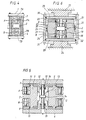
- This transformer and two electrically controlled basic spring elements AB mechanically counter-connected as shown in Figure 4 constitute a preferred embodiment of a complete, electrically controlled spring element according to the invention and will be described with reference to Figure 5.
- the complete spring element consists of a body with a central symmetry plane as shown in Figure 5. In a preferred embodiment the body is cylindrical, with central cylindrical openings in the end surfaces for power outputs.
- the construction consists of an upper lid 5, a lower lid 6 and two rings 7 and 8 abutting the inner side of the upper and lower lids, respectively.
- the rings may also constitute an integral part of each lid.
- the construction is made up of two complete basic spring elements according to Figure 4. Each of these is located between the lids and on opposite sides and equidistant from the symmetry axis (mid-line in Figure 5) of the symmetry plane. Lids, rings and basic spring elements are held together by a screw arrangement, not shown. Inside the construction is a first plunger 9 having two diametrically located power outputs 2, located centrally and extending radially outwards from the plunger, corresponding to the power outputs on the basic spring element according to Figure 4.
- This first plunger thus moves synchronously with the upward and downward movement of the T-rods which, as mentioned above, in practice move maximally 50-100 ⁇ m.
- the upward and downward movement of this plunger is controlled by the inner surface of the rings 7 and 8 and a seal is located in grooves in plunger and rings in the form of low-friction seals 10 and 11, permitting the upward and downward movement of the plunger.
- This first plunger has a central, cylindrical through-opening with a lining 12, inside which a second plunger 13 can move.
- the second plunger is sealed by a piston ring 14 to the lining of the first plunger.
- a tapped pin 15 runs centrally through the second plunger and is guided by said central openings in the lids 5 and 6. Seals in the form of piston rings 16 and 17 are also provided between each lid and the central pin.
- the free, sealed space defined by the top of the first plunger, the inner surface of lid 5, the lining 12, the central pin and the top of the second plunger is filled with a low-compressive medium having low internal friction, e.g. silicon oil, under a certain over-pressure.
- the corresponding space in the lower half of the complete spring element is also filled with the same medium under the same over-pressure.
- the second plunger with its central pin will move in the opposite direction to the first plunger with an amplitude/stretch gain corresponding to the ratio between the active hydraulic areas of the two plungers.
- an active area ratio of 200 which, with a maximum movement of about 100 ⁇ m of the first plunger, would give a movement of 20 mm for the second plunger including its central pin.
- the available force on the central pin will be a corresponding number of times lower than the force on the output shoulders 2.
- An extremely simple way of influencing the stretch increase or the tensile or compressive force is to alter the ratio between the active areas of the plungers. This can be done, for instance, by altering the inner diameter of the lining ring 12 and thus the outer diameter of the second plunger.
- the number of pairs of mechanically connected electrically controlled basic spring elements according to Figure 4 may be increased.
- the basic spring elements are preferably located in a symmetrical or mirror-symmetrical configuration.
- the shape of the complete spring element need not necessarily be cylindrical.
- the lids, and thus the outer contours, may have elliptical, rectangular, quadratic or some other shape depending on the application.
- FIG. 6 An electrically controlled spring element having only one basic spring element AB according to Figure 4 is also possible.
- An embodiment of this kind with substantially the same principle for the mechanical transformer is shown in Figure 6.
- the basic spring element AB is located centrally.
- the power outputs 2 are in engagement with a plunger 18 surrounding the basic spring element and controlled by two sleeves 19 and 20.
- the plunger is sealed from the outer spaces 21 and 22, filled with low-compressive medium, by means of low-friction seals 23 and 24.
- the piston 18 is provided with an outer lining ring 25 against which an outer plunger 26 can move.
- This plunger constitutes an integral part of an outer, tubular casing 27 from which power output occurs from the electrically controlled spring element.
- the tubular casing is guided by the two lids 28 and 29.
- the two spaces 21 and 22 filled with low-compressive medium are provided with seals 30 and 31 between the casing and respective lids, and a seal 32 between the spaces 21 and 22.
- Other external positioning means are supports 33 and 34.
- the plungers 18 and 26 move in opposite directions and the amplitude/stretch gain is dependent on the ratio between the hydraulic areas of the plungers.
Landscapes
- Engineering & Computer Science (AREA)
- General Engineering & Computer Science (AREA)
- Mechanical Engineering (AREA)
- Springs (AREA)
- General Electrical Machinery Utilizing Piezoelectricity, Electrostriction Or Magnetostriction (AREA)
- Surgical Instruments (AREA)
- Dry Shavers And Clippers (AREA)
- Registering, Tensioning, Guiding Webs, And Rollers Therefor (AREA)
Abstract
Description
- The invention relates to an electrically controlled spring element according to the precharacterising part of
Claim 1. - Besides being perfectly suitable for use as a passive spring, such an electrically controlled spring element can be specially designed to provide it with extremely good frequency properties. This enables it to be used as basic element in equipment for vibration-free suspension of extremely sensitive instruments, for instance, vibration-free mechanical transmission, as active mechanical moderator or actuator, controllable inductance, electromechanical transformer, etc.
- The main and essential difference between a passive, conventional spring element, and an electrically controllable spring element resides in the property of the latter that its spring constant, spring force and stretch can all be electrically controlled. By applying stationary electrical control, the spring element can be caused within an extremely short time, in the region of 50 ms, to behave as a pre-stressed, mechanically passive spring element. Thanks to the good frequency properties the element can be designed with, it can also be altered in a very short time from one static, spring-force state into another and can thus also respond very well to dynamic electric control.
- The fundamental principle for electrically controlled spring elements has long pertained to the state of the art. However, hitherto known applications are primarily for mechanical actuators, such as sonar, and in connection with certain types of transducers. The unique properties which can be achieved are due to the active material in the spring element consisting of a magnetic core having very special properties, i.e. its physical form, E-module and relative permeability are altered when the material is subjected to varying degrees of magnetization and also when it is in various states of mechanical stress.
- It has been known for some time that the so-called rare earth metals samarium (Sm), terbium (Tb), dysprosium (Dy), holmium (Ho), erbium (Er), and so on, exhibit extremely high magnetostrictive behavior at very low temperatures. If an ordinary metal material, for instance, has a magnetostrictive linear expansion of about 10 µm/m, the rare earth metals have a linear expansion of up to 4400 µm/m at cryotemperature. Unfortunately, however, this pronounced magnetostrictive effect appears only at extremely low temperatures, what greatly curtails the list of possible applications.
- It was discovered relatively soon, however, that extremely high magnetostriction in comparison with ordinary metals could also be obtained at room temperature, or even temperatures up to several hundred degrees, by alloying the rare earth metals with iron (Fe) and nickel (Ni) inter alia. Purely practically it is possible to obtain magnetostriction in the order of 2000 µm/m at room temperature. This in any case constitutes a
linear expansion 150 times that of ordinary metallic substances. Elements made of alloys between ferro-metals and the rare earth metals can thus be utilized in many applications based on the magnetostrictive effect, which would previously have been impossible or which did not give sufficient effect to be economically exploitable. - The properties of these alloys have been documented in articles such as "Giant magnetostriction gives more sensitive transducers" by L. Jansson, published in "Elteknik med aktuel elektronik" 1984:16, page 57, and in a multitude of patents, e.g. US-A-4 308 474, "Rare Earth-Iron Magnetostrictive Materials and Devices using these Materials". This publication states a plurality of different alloys. However, it is intimated here, without any further description, that these materials can be used as magnetostrictive elements in magnetostrictive transducers, time-delaying elements, variable frequency oscillators and filters.
- US-A-4 378 258 shows a method of converting magnetic energy into mechanical energy, in which the mechanical energy appears in a change in the dimensions of a special alloy caused by a change in the magnetic field. These particular alloys have now been used in several practical applications, e.g. in the form of a SONAR, see US-A-4 438 509, and in valves, see US-A-4 158 368.
- The rare earth metals are generally expensive. Furthermore, the production of materials containing these alloys entails relatively complicated processes. Intensive research has therefore been carried on to develop alloys with optimal data both from the cost and the manufacturing aspects. The best composition discovered so far consists of Tb0.27DY0.73Fe1.9, and the alloy has been called TERFENOL-D. The material is currently manufactured in a limited number of places in the world and is supplied in the form of cylindrical rods having a diameter of about 6 to 40 mm and a length of up to about 300 mm.
- The invention aims at developing an electrically controlled spring element of the above-mentioned kind in which the necessary mechanical prestressing which is required to avoid tensile strain in the magnetostrictive material is provided in a very economical way without the need for excess magnetic energy. A further object of the invention is to design an electrically controlled spring element that exhibits a considerably magnified stretch in comparison to the stretch obtainable in the proper magnetostrictive material.
- To achieve this aim the invention suggests an electrically controlled spring element according to the introductory part of
Claim 1, which is characterized by the features of the characterizing part ofClaim 1. - Further developments of the invention are characterized by the features of the additional claims.
- The invention will be described with the aid of graphs showing the technical capabilities of the material and figures giving examples of how an electrically controlled spring element according to the invention may be constructed. In particular the accompanying drawings show - by way of example - in
- Figure 1 the ratio between a magnetizing magnetic field strength H applied axially on a TERFENOL rod, hereinafter called T-rod, and the relative linear expansion when the T-rod is subjected to various mechanical stress conditions,
- Figure 2 how the E-module of the material varies dependent on the same parameters,
- Figure 3 the ratio between the magnetic field strength H and the magnetic flux density B for various mechanical stress conditions,
- Figure 4 an electrically controlled basic spring element according to the invention and how mechanical prestressing can be achieved in such an element,
- Figure 5 a preferred embodiment of a complete spring element, including a mechanical transformer to increase the magnetostrictive stretch,
- Figure 6 an alternative embodiment of a complete spring element according to the invention,
- Figures 7 and 8 show various control characteristics for an electrically controlled basic spring element.
- In Figure 1 the relative linear expansion Δl/l (mm/m) is shown for a T-rod which is subjected to a magnetizing magnetic field strength H (A/m) along the symmetry axis of the rod. The graph shows how the linear expansion is dependent on the mechanical stress (MPa) applied on the T-rod.
- In Figure 2 the equivalent ratio is shown between the magnetizing field strength H and the E-module (N/m²) of the material at various mechanical stress conditions.
- In Figure 3 the ratio is shown between the magnetizing field strength H and the corresponding magnetic flux density (tesla) for various mechanical stress conditions. Of the properties exhibited by T-rods the one which has been utilized most is the T-rods' great alteration in length, compared with known magnetic materials. This is particularly evident from patent specifications such as US-A-4 438 509 "Transducer with Tensioned-Wire Precompression",
GB 2 174 863 A "Permanent magnet biased magnetostrictive transducer", WO 85/02084 "Low Frequency Sound Transducer" and WO 86/03888 "A Rare Earth Flextensional Transducer". The alteration in length of the T-rod is used here to cause some type of membrane to oscillate in time with the magnetization. - In an electrically controlled spring element according to the invention it is the mechanical properties which are utilized more in isolation, but of course intimately associated with the linear alterations in the T-rod. Although relatively modest, the alteration in length which can be obtained at various magnetization conditions of the highly magnetostrictive materials means that the stretch range, which may be up to about 100 µm, will in many applications be insufficient in a spring element based solely on the linear expansion of a T-rod.
- A spring element according to the invention therefore also includes a mechanical transmission between the highly magnetostrictive material and the mechanical load, in the form of a mechanical transformer permitting a considerably increased stretch range.
- As will be seen in Figure 1, the magnetostriction is dependent on the magnetizing field strength H. If the magnetization in a quasi-stationary state is to be proportional to an applied time-varying magnetization, therefore, the T-rod must be premagnetized, preferably by means of permanent magnets. According to a known method, e.g. described in WO 86/03888, this can be achieved by dividing the T-rod in axial direction into a number of pellets between which permanent magnets are placed, in order to ensure a magnetization distributed as uniformly as possible.
- In order to obtain the best possible dynamic properties various forms of lamination may be advisable, such as dividing the T-rod axially into a number of straight lamina of substantially equal width, by slicing the T-rod as shown in WO 86/03888, or by producing a spiral air gap by means of spark treating.
- In the case of large dynamic loads on a spring element based on T-rods, a correspondingly large dynamic magnetizing field strength H is also required. The excitation coil surrounding the T-rod shall be able to generate this. The dynamic magnetization can be effected in conventional manner by increasing the supply voltage at increasing frequency. Another method might be the use of a coil system consisting of a number of coaxial, concentric coils supplied via galvanically separated, frequency-selecting amplifiers in such a way that the innermost coil is supplied by high-frequency components and the outermost coil is connected to an amplifier step with low frequency components.
- To obtain an optimum operating point with a given pre-magnetization of a T-rod forming part of an electrically controlled spring element, there must also be adequate mechanical pre-stressing. Such mechanical pre-stressing can be achieved in many ways. An example is shown in US-A-4 438 509 already mentioned, where the T-rod is used in a SONAR application. The T-rod is here secured between two yokes and the mechanical pre-stressing in the rod is achieved by tensioning wires pulling the yokes together. Of course ordinary helical extension springs may also be used.
- Unfortunately, the tensile strength of a T-rod is considerably lower than its compressive strength. Mechanical pre-stressing is thus also necessary for T-rods under strong mechanical and electrical loads, to prevent them from being subjected to tensile stress. The mechanical pre-stressing required to prevent the occurrence of tensile stress in the T-rod, in the case of transient magnetic excitation and considerable mechanical load, is considerably greater than the pre-stressing required when taking into consideration only the selection of optimum operating point.
- The above belongs substantially to the state of the art concerning the use of T-rods in various types of actuators and transducers. To obtain a technically acceptable electrically controlled spring element according to the invention it is advisable, and sometimes necessary depending on the application, to provide the element with one or more of the technical partial solutions described.
- The basis of an electrically controlled spring element according to the invention in an elementary element, known per se, comprising a rod of highly magnetostrictive material, pre-magnetized by permanent magnets, and surrounded by an excitation coil.
- Characteristic of the invention is that two such elementary elements A and B comprised in Figure 4 form an electrically controlled so-called "basic spring element" (AB). The elementary elements are mounted in a
frame 1, the rods TA and TB being aligned with their axial centre lines and being separated by an intermediate transmission element with apower output 2. Pre-magnetization is suitably effected by dividing the T-rods into axially aligned pellets with permanent magnets inserted between them, indicated symbolically in Figure 4 as PA and PB. The excitation coils are designated 3 and 4. The magnetization circuits for the two elements should be spaced such that they do not noticeably influence each other. Contrary to the mechanical pre-stressing methods described, pre-stressing according to the invention is effected by mechanically counter-connecting the two elementary elements comprised in the basic spring element. This can be achieved by ensuring that the magnetic orientation of the pre-magnetization and the excitation coils are always directed in a certain manner, i.e. the external electrically controlled magnetization must always be directed in the same direction as the pre-magnetization in one element and always directed opposite to the pre-magnetization direction in the other element. Thus, regardless of the direction of the excitation current in the coils, one of the elementary elements will always, and alternating with the current direction, be more compressively pre-stressed than the other elementary element. Thus no pre-stressing in the proper mechanical sense will be necessary. The least compressively pre-stressed element will thus constitute pre-stressing for the most compressively pre-stressed element. The difference in spring force between the two elementary elements constitutes the force supplied to the load. - An example of the coordination between the pre-magnetization directions and the direction of the electrical excitation required to achieve this form of "mechanical" pre-stressing can be seen in Figure 4. If the coils are connected in order to magnetically act in the same direction, the winding direction marked by points (.), the pre-magnetization in the two elements A and B shall be directed in opposite directions, e.g. with both S poles or both N poles facing each other. Thus, regardless of the direction of the excitation current, one of the elements will be more compressively pre-stressed than the other.
- If magnetization is harmonious and the coils are otherwise identical, they may suitably be connected in series. In the case of broad-band magnetization the elementary elements may be supplied from different sources, mutually synchronized. Control is increased by this arrangement both because the resonance frequency of the system can be controlled and because no unnecessary energy is utilized to stress springs, as is the case in the state of the art when passive springs are used in strong transient magnetization. As explained, this is because the material must be protected against tensile stress by considerably over-dimensioned, mechanical pre-stressing. Furthermore, if passive springs are used for pre-stressing, they will also serve as pull-off springs for the previously mentioned simple spring elements, as e.g. sonars, etc.
- As mentioned, an electrically controlled spring element according to the invention includes a mechanical transformer composed in principle as a differential plunger arrangement in order to increase the stretch range further than is permitted by the T-rod. This transformer and two electrically controlled basic spring elements AB mechanically counter-connected as shown in Figure 4 constitute a preferred embodiment of a complete, electrically controlled spring element according to the invention and will be described with reference to Figure 5. The complete spring element consists of a body with a central symmetry plane as shown in Figure 5. In a preferred embodiment the body is cylindrical, with central cylindrical openings in the end surfaces for power outputs. The construction consists of an
upper lid 5, alower lid 6 and tworings first plunger 9 having two diametrically locatedpower outputs 2, located centrally and extending radially outwards from the plunger, corresponding to the power outputs on the basic spring element according to Figure 4. This first plunger thus moves synchronously with the upward and downward movement of the T-rods which, as mentioned above, in practice move maximally 50-100 µm. The upward and downward movement of this plunger is controlled by the inner surface of therings - This first plunger has a central, cylindrical through-opening with a
lining 12, inside which asecond plunger 13 can move. The second plunger is sealed by apiston ring 14 to the lining of the first plunger. A tappedpin 15 runs centrally through the second plunger and is guided by said central openings in thelids piston rings lid 5, the lining 12, the central pin and the top of the second plunger is filled with a low-compressive medium having low internal friction, e.g. silicon oil, under a certain over-pressure. The corresponding space in the lower half of the complete spring element is also filled with the same medium under the same over-pressure. - When the basic spring elements are influenced electrically the second plunger with its central pin will move in the opposite direction to the first plunger with an amplitude/stretch gain corresponding to the ratio between the active hydraulic areas of the two plungers. From the purely practical point of view there is no particular problem in achieving an active area ratio of 200 which, with a maximum movement of about 100 µm of the first plunger, would give a movement of 20 mm for the second plunger including its central pin. According to the energy principle, therefore, the available force on the central pin will be a corresponding number of times lower than the force on the output shoulders 2.
- An extremely simple way of influencing the stretch increase or the tensile or compressive force is to alter the ratio between the active areas of the plungers. This can be done, for instance, by altering the inner diameter of the
lining ring 12 and thus the outer diameter of the second plunger. - To allow increased power output with otherwise identical design and stretch, the number of pairs of mechanically connected electrically controlled basic spring elements according to Figure 4 may be increased. In order to avoid uneven loading, however, the basic spring elements are preferably located in a symmetrical or mirror-symmetrical configuration.
- Of course, the shape of the complete spring element need not necessarily be cylindrical. The lids, and thus the outer contours, may have elliptical, rectangular, quadratic or some other shape depending on the application.
- An electrically controlled spring element having only one basic spring element AB according to Figure 4 is also possible. An embodiment of this kind with substantially the same principle for the mechanical transformer is shown in Figure 6. The basic spring element AB is located centrally. The power outputs 2 are in engagement with a
plunger 18 surrounding the basic spring element and controlled by twosleeves outer spaces piston 18 is provided with anouter lining ring 25 against which anouter plunger 26 can move. This plunger constitutes an integral part of an outer,tubular casing 27 from which power output occurs from the electrically controlled spring element. The tubular casing is guided by the twolids spaces seals seal 32 between thespaces supports plungers - For all the embodiments described, and similar embodiments covered by the invention, it can be established that for the complete spring element all internal forces are compressive forces, that they can emit both compressive and tensile forces and that a relatively small quantity of hydraulic fluid is required.
- Obviously, from the design point of view, the embodiments described and mentioned can be combined in modular manner in various ways as far as the actual basic element and the mechanical transformer are concerned.
- The control obtainable with the electrically controlled basic spring element, and thus also for a complete electrically controlled spring element such as that shown in Figure 5 is evident from the characteristics shown in Figures 7 and 8. As can be seen, the scales are indicated only in standard values since the values for a specific design depend on the desired force or stretch for the application in question. The excitation current is a suitable control parameter.
Claims (3)
Applications Claiming Priority (2)
| Application Number | Priority Date | Filing Date | Title |
|---|---|---|---|
| SE8701138 | 1987-03-19 | ||
| SE8701138A SE8701138D0 (en) | 1987-03-19 | 1987-03-19 | ELECTRICALLY CONTROLLED SPRING ELEMENT |
Publications (2)
| Publication Number | Publication Date |
|---|---|
| EP0283880A1 true EP0283880A1 (en) | 1988-09-28 |
| EP0283880B1 EP0283880B1 (en) | 1993-01-13 |
Family
ID=20367915
Family Applications (1)
| Application Number | Title | Priority Date | Filing Date |
|---|---|---|---|
| EP88103936A Expired - Lifetime EP0283880B1 (en) | 1987-03-19 | 1988-03-12 | Electrically controlled spring element |
Country Status (6)
| Country | Link |
|---|---|
| US (1) | US4802660A (en) |
| EP (1) | EP0283880B1 (en) |
| JP (1) | JPS63254243A (en) |
| DE (1) | DE3877392T2 (en) |
| NO (1) | NO178710C (en) |
| SE (1) | SE8701138D0 (en) |
Cited By (6)
| Publication number | Priority date | Publication date | Assignee | Title |
|---|---|---|---|---|
| EP0379075A1 (en) * | 1989-01-16 | 1990-07-25 | Asea Brown Boveri Ab | Magnetic circuit |
| EP0425954A1 (en) * | 1989-10-31 | 1991-05-08 | Abb Atom Ab | Device for transmission of movement and compressive force |
| EP0443873A1 (en) * | 1990-02-23 | 1991-08-28 | Kabushiki Kaisha Toshiba | Magnetostriction type actuator |
| US5052529A (en) * | 1989-03-16 | 1991-10-01 | Topexpress Limited | Active control of vibration |
| US5238232A (en) * | 1991-10-09 | 1993-08-24 | Honda Giken Kogyo Kabushiki Kaisha | Self-expanding mount |
| WO2009044180A1 (en) * | 2007-10-03 | 2009-04-09 | Feonic Plc | Magnetostrictive actuator |
Families Citing this family (10)
| Publication number | Priority date | Publication date | Assignee | Title |
|---|---|---|---|---|
| SE466467B (en) * | 1987-12-10 | 1992-02-17 | Asea Atom Ab | WATER PUMP DRIVEN FROM ELEMENTS OF A JETTAGMAGNOSTICTIVE MATERIAL |
| SE464933B (en) * | 1989-12-21 | 1991-07-01 | Wabco Holdings Sab | KRAFTAKTUATORARRANGEMANG |
| DE4032555A1 (en) * | 1990-10-13 | 1992-04-16 | Teves Gmbh Alfred | Electromagnetically-operated pump for hydraulic braking system - uses magnetostrictive actuator acting on piston or membrane for varying vol. of pump pressure space |
| WO1997038242A1 (en) * | 1996-04-08 | 1997-10-16 | Delta Tooling Co., Ltd. | Magnetic spring having damping characteristics and vibration mechanism having same |
| JP3725272B2 (en) * | 1996-12-27 | 2005-12-07 | 株式会社デルタツーリング | Vibration generation mechanism |
| JPH1130274A (en) * | 1997-05-15 | 1999-02-02 | Delta Tsuuring:Kk | Vibrational mechanism with magnetic spring |
| KR100281474B1 (en) | 1997-05-16 | 2001-02-01 | 후지타 히토시 | Energy extracting mechanism having a magnetic spring |
| US20070210527A1 (en) * | 2006-03-01 | 2007-09-13 | Yoshio Yano | Seal device |
| CN104976263B (en) * | 2015-05-14 | 2017-03-15 | 上海交通大学 | A kind of symmetric form electromagnetic actuator |
| CN105840707B (en) * | 2016-06-20 | 2017-10-24 | 中国舰船研究设计中心 | Electromagnetic actuator peculiar to vessel |
Citations (4)
| Publication number | Priority date | Publication date | Assignee | Title |
|---|---|---|---|---|
| US4438509A (en) * | 1981-05-18 | 1984-03-20 | Raytheon Company | Transducer with tensioned-wire precompression |
| WO1985002084A1 (en) * | 1983-10-31 | 1985-05-09 | Gould Inc. | Low frequency sound transducer |
| WO1986003888A1 (en) * | 1984-12-19 | 1986-07-03 | Gould Inc. | A rare earth flextensional transducer |
| GB2174863A (en) * | 1985-05-10 | 1986-11-12 | Raytheon Co | Permanent magnet biased magnetostrictive transducer |
Family Cites Families (5)
| Publication number | Priority date | Publication date | Assignee | Title |
|---|---|---|---|---|
| US4378258A (en) * | 1972-03-16 | 1983-03-29 | The United States Of America As Represented By The Secretary Of The Navy | Conversion between magnetic energy and mechanical energy |
| US4158368A (en) * | 1976-05-12 | 1979-06-19 | The United States Of America As Represented By The Secretary Of The Navy | Magnetostrictive transducer |
| US4308474A (en) * | 1979-11-14 | 1981-12-29 | The United States Of America As Represented By The Secretary Of The Navy | Rare earth-iron magnetostrictive materials and devices using these materials |
| US4642802A (en) * | 1984-12-14 | 1987-02-10 | Raytheon Company | Elimination of magnetic biasing using magnetostrictive materials of opposite strain |
| US4845450A (en) * | 1986-06-02 | 1989-07-04 | Raytheon Company | Self-biased modular magnetostrictive driver and transducer |
-
1987
- 1987-03-19 SE SE8701138A patent/SE8701138D0/en unknown
-
1988
- 1988-03-12 EP EP88103936A patent/EP0283880B1/en not_active Expired - Lifetime
- 1988-03-12 DE DE8888103936T patent/DE3877392T2/en not_active Expired - Fee Related
- 1988-03-14 NO NO881123A patent/NO178710C/en not_active IP Right Cessation
- 1988-03-15 US US07/168,417 patent/US4802660A/en not_active Expired - Lifetime
- 1988-03-17 JP JP63064642A patent/JPS63254243A/en active Pending
Patent Citations (4)
| Publication number | Priority date | Publication date | Assignee | Title |
|---|---|---|---|---|
| US4438509A (en) * | 1981-05-18 | 1984-03-20 | Raytheon Company | Transducer with tensioned-wire precompression |
| WO1985002084A1 (en) * | 1983-10-31 | 1985-05-09 | Gould Inc. | Low frequency sound transducer |
| WO1986003888A1 (en) * | 1984-12-19 | 1986-07-03 | Gould Inc. | A rare earth flextensional transducer |
| GB2174863A (en) * | 1985-05-10 | 1986-11-12 | Raytheon Co | Permanent magnet biased magnetostrictive transducer |
Cited By (9)
| Publication number | Priority date | Publication date | Assignee | Title |
|---|---|---|---|---|
| EP0379075A1 (en) * | 1989-01-16 | 1990-07-25 | Asea Brown Boveri Ab | Magnetic circuit |
| US5052529A (en) * | 1989-03-16 | 1991-10-01 | Topexpress Limited | Active control of vibration |
| EP0425954A1 (en) * | 1989-10-31 | 1991-05-08 | Abb Atom Ab | Device for transmission of movement and compressive force |
| EP0443873A1 (en) * | 1990-02-23 | 1991-08-28 | Kabushiki Kaisha Toshiba | Magnetostriction type actuator |
| US5238232A (en) * | 1991-10-09 | 1993-08-24 | Honda Giken Kogyo Kabushiki Kaisha | Self-expanding mount |
| EP0536761B1 (en) * | 1991-10-09 | 1996-02-07 | Honda Giken Kogyo Kabushiki Kaisha | Self-expanding mount for controlling transmission of vibration from a vibration source to a base |
| WO2009044180A1 (en) * | 2007-10-03 | 2009-04-09 | Feonic Plc | Magnetostrictive actuator |
| US8471432B2 (en) | 2007-10-03 | 2013-06-25 | Feonic Plc | Magnetostrictive actuator |
| CN101821871B (en) * | 2007-10-03 | 2013-11-13 | Feonic公共有限公司 | Magnetostrictive actuator |
Also Published As
| Publication number | Publication date |
|---|---|
| SE8701138D0 (en) | 1987-03-19 |
| NO881123L (en) | 1988-09-20 |
| US4802660A (en) | 1989-02-07 |
| JPS63254243A (en) | 1988-10-20 |
| NO178710B (en) | 1996-02-05 |
| NO881123D0 (en) | 1988-03-14 |
| DE3877392T2 (en) | 1993-08-19 |
| DE3877392D1 (en) | 1993-02-25 |
| EP0283880B1 (en) | 1993-01-13 |
| NO178710C (en) | 1996-05-15 |
Similar Documents
| Publication | Publication Date | Title |
|---|---|---|
| EP0283880B1 (en) | Electrically controlled spring element | |
| DE69935334T2 (en) | LOW FREQUENCY SCHWINGER | |
| US7255290B2 (en) | Very high speed rate shaping fuel injector | |
| EP0838095B1 (en) | A method for producing motion and force by controlling the twin structure orientation of a material and its uses | |
| US6037682A (en) | Integrated multi-mode transducer and method | |
| JP2006521198A (en) | Damping / actuating device including magnetostrictive material, vibration damping device, and method of using the device | |
| US11302862B1 (en) | Magnetostrictive actuator with center bias | |
| EP0379075B1 (en) | Magnetic circuit | |
| JP2756471B2 (en) | Method for manufacturing radially oriented magnet and radially oriented magnet | |
| US6300855B1 (en) | Hysteresis reduction in giant magnetostrictive materials | |
| JPH05198863A (en) | Magnetostrictive element | |
| Flatau et al. | High bandwidth tunability in a smart vibration absorber | |
| JPH05236595A (en) | Magnetostriction displacement generator | |
| US10153682B2 (en) | Self-centering electromagnetic transducers | |
| JP3315235B2 (en) | Magnetostrictive actuator | |
| US20200188956A1 (en) | Vibration source | |
| JP3332125B2 (en) | Magnetostrictive actuator | |
| JP3057107B2 (en) | Magnetostrictive actuator | |
| US3439199A (en) | Magnetostrictive unit | |
| Ubaidillah et al. | Design and fabrication of magnetorheological elastomer vibration isolator/Ubaidillah...[et al.] | |
| JPH05282044A (en) | Magnetostrictive actuator | |
| EP4322552A2 (en) | Loudspeakers | |
| JP3131090U (en) | Magnetostrictive actuator | |
| JP2916879B2 (en) | Manufacturing method of radially oriented magnet | |
| JPH03285577A (en) | Magnetostriction type vibrating fan |
Legal Events
| Date | Code | Title | Description |
|---|---|---|---|
| PUAI | Public reference made under article 153(3) epc to a published international application that has entered the european phase |
Free format text: ORIGINAL CODE: 0009012 |
|
| AK | Designated contracting states |
Kind code of ref document: A1 Designated state(s): DE GB SE |
|
| 17P | Request for examination filed |
Effective date: 19890131 |
|
| 17Q | First examination report despatched |
Effective date: 19910723 |
|
| GRAA | (expected) grant |
Free format text: ORIGINAL CODE: 0009210 |
|
| AK | Designated contracting states |
Kind code of ref document: B1 Designated state(s): DE GB SE |
|
| REF | Corresponds to: |
Ref document number: 3877392 Country of ref document: DE Date of ref document: 19930225 |
|
| PLBE | No opposition filed within time limit |
Free format text: ORIGINAL CODE: 0009261 |
|
| STAA | Information on the status of an ep patent application or granted ep patent |
Free format text: STATUS: NO OPPOSITION FILED WITHIN TIME LIMIT |
|
| 26N | No opposition filed | ||
| EAL | Se: european patent in force in sweden |
Ref document number: 88103936.6 |
|
| REG | Reference to a national code |
Ref country code: GB Ref legal event code: IF02 |
|
| PGFP | Annual fee paid to national office [announced via postgrant information from national office to epo] |
Ref country code: SE Payment date: 20020306 Year of fee payment: 15 |
|
| PGFP | Annual fee paid to national office [announced via postgrant information from national office to epo] |
Ref country code: GB Payment date: 20020313 Year of fee payment: 15 |
|
| PGFP | Annual fee paid to national office [announced via postgrant information from national office to epo] |
Ref country code: DE Payment date: 20020327 Year of fee payment: 15 |
|
| PG25 | Lapsed in a contracting state [announced via postgrant information from national office to epo] |
Ref country code: GB Free format text: LAPSE BECAUSE OF NON-PAYMENT OF DUE FEES Effective date: 20030312 |
|
| PG25 | Lapsed in a contracting state [announced via postgrant information from national office to epo] |
Ref country code: SE Free format text: LAPSE BECAUSE OF NON-PAYMENT OF DUE FEES Effective date: 20030313 |
|
| PG25 | Lapsed in a contracting state [announced via postgrant information from national office to epo] |
Ref country code: DE Free format text: LAPSE BECAUSE OF NON-PAYMENT OF DUE FEES Effective date: 20031001 |
|
| EUG | Se: european patent has lapsed | ||
| GBPC | Gb: european patent ceased through non-payment of renewal fee |
Effective date: 20030312 |