EP0282466A2 - Method for measuring X-rays or gamma radiation and device for this - Google Patents
Method for measuring X-rays or gamma radiation and device for this Download PDFInfo
- Publication number
- EP0282466A2 EP0282466A2 EP88850062A EP88850062A EP0282466A2 EP 0282466 A2 EP0282466 A2 EP 0282466A2 EP 88850062 A EP88850062 A EP 88850062A EP 88850062 A EP88850062 A EP 88850062A EP 0282466 A2 EP0282466 A2 EP 0282466A2
- Authority
- EP
- European Patent Office
- Prior art keywords
- radiation
- long
- filament
- narrow
- measured
- Prior art date
- Legal status (The legal status is an assumption and is not a legal conclusion. Google has not performed a legal analysis and makes no representation as to the accuracy of the status listed.)
- Granted
Links
Images
Classifications
-
- G—PHYSICS
- G01—MEASURING; TESTING
- G01T—MEASUREMENT OF NUCLEAR OR X-RADIATION
- G01T1/00—Measuring X-radiation, gamma radiation, corpuscular radiation, or cosmic radiation
- G01T1/36—Measuring spectral distribution of X-rays or of nuclear radiation spectrometry
Definitions
- the object of the invention to enable spectrometry for high energy electromagnetic radiation by means of Compton scattering.
- This is done by utilizing as scattering element a long and narrow filament or a long and narrow rod.
- a distortion of the measured spectrum is obtained also here but it will be possible by the very use of such a rod or filament to reconstruct by calculations the original spectrum with a very good accuracy.
- a filament or rod a very well-defined scattering angle is obtained.
- the scattering from the surrounding medium (air) is minimized as it is measured from the volume determined by the intersecting beam paths of the beam incident from the source and the beam path of the detector.
- a very long and narrow filament or a very long and narrow rod having a circular cross-sectional area a possibility of varying direction is obtained as the scattering volume does not vary with the scattering angle.
- a material for the rod or filament having a low average atomic number By using in a suitable further development of the invention a material for the rod or filament having a low average atomic number the Doppler effect is reduced which, in turn, brings a better reproduction of adjacent peaks in the spectrum.
- suitable materials polyethylene, lucite or another material having a low average atomic number is suggested.
- the reconstruction of the primary spectrum from the measured spectrum is carried out by means of the following formulas which have recently been produced by the inventors.
- N h v(hvc)d(hvc) is the number of photons registered by the detector between the energies hvc and hvc+d(hv c ) after correction for the distortion of the detector itself (detector response).
- N e the total number of electrons in the scatterer gives the radiation damping in the scatterer and in the air (attenuation).
- 1 (a) the distance in air between the scatterer and the detector.
- u a the attenuation coefficient of air.
- us the attenuation coefficient of the scatterer.
- r the radius of the circular and filamentous scatterer
- hvc the energy of the Compton-scattered radiation
- hvo the incoming energy resulting from the relation
- the scattering angle 0 is found in the equations (E1) and (E3).
- the self energy of the electron mc 2.
- Equation (E1) AH is the solid angle element subtend by the detector from a point in the scatterer on an average.
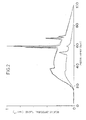
- Equation (E1) ⁇ Po,hv(hvo) represents the approximately reconstructed radiation intensity (before scattering). This corresponds to Fig. 2, dotted line, except the peaks.
- the average kinetic energy T of the electrons in the scatterer is also included.
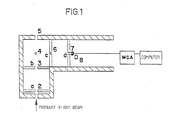
- Fig. 1 shows schematically a scattering chamber according to the invention and Fig. 2 shows the radiation curves already treated.
- the scattering chamber shown in Fig. 1 is substantially angular.
- In the first angle arm there is an aperture for incident, highly intensive x-radiation.
- Within the chamber there are a first collimator 2 and a second collimator 3 defining the radiation which thereafter hits the filament 4.
- the radiation passing the filament and past it passes out through an aperture 5 on the other side of the scattering chamber.
- two collimators 6 and 7 are arranged and the radiation scattered in the filament passes through the collimators to a detector 8 in the other arm of the scattering chamber.
- the detector is a High parity Ge-detector connected to a multichannel analyzer. This, in turn, is connected to a data processing unit reconstructing spectra according to the equations (E1) - (E4).
- a-c are collimators of the dimensions 3mm x 25 mm.
- d is a collimator of the diameter 3 mm.
- D is the Ge-detector.
- 0 is the scatterer.
- the drawing is made almost on a correct scale. It is apparent from this that the chamber can easily be used on place in most existing x-ray equipments.
- the material of the filament is polyethylene, lucite or another material of a low average atomic number providing rapid and precise reconstructions. In the example shown air scattering corresponds to a very small portion of the totally detected intensity.
Landscapes
- Physics & Mathematics (AREA)
- Spectroscopy & Molecular Physics (AREA)
- Health & Medical Sciences (AREA)
- Life Sciences & Earth Sciences (AREA)
- General Physics & Mathematics (AREA)
- High Energy & Nuclear Physics (AREA)
- Molecular Biology (AREA)
- Measurement Of Radiation (AREA)
- Analysing Materials By The Use Of Radiation (AREA)
Abstract
Description
- Clinical use of quantitative X-ray methods such as the determination of bone mineral content or tissue density for dose planning purposes demand a knowledge of the energy distribution of the x-rays. Spectrometry with germanium detectors requires counting rates of about 50 000 pulses/second or less in order to avoid overlapping pulses (pile ups). With the high fluence from clinical x-ray tubes appropriate counting rates is attained only if the distance between the x-ray source and the detector is several meters and the collimators have diameters that are as small as 0.025-0.5 mm.
- This direct measuring method cannot be used in practice in clinical x-ray laboratories due to space limitations. Fig 2, the upper continuous line, shows a spectrum measured directly.
- Due to the practical difficulties of the direct measuring method it is only used to a small extent. Moreover, there will be problems with the alignment of the detector because it is easy to measure, by mistake, beside or on the edge of the x-ray focus which, of course, is not intended.
- An extremely efficient method for reduction of the pulse rate is utilizing Compton scattering i.e. the radiation is scattered of the electrons in a material. However, when the radiation is scattered in this way energy is lost to the electrons and as a result of this the original spectrum will be distorted, the consequence being, in turn, that this is no longer representative. Accordingly Compton scattering has not been utilized so fasr as a basis of spectrometry. Fig 2, the lower curve, shows a Compton scattered spectrum.
- However, we have developed this method further which has previously been utilized i.a. by Yaffe et al.to get a very good energy resolution and to make the method applicable in clinical connections. By a special choice of scatterer (a long and narrow filament or a long and narrow rod) a very well-defined scattering angle is obtained optimizing the geometrical energy resolution. Moreover, as distinguished from what has been done in previous embodiments, correct scattering algorithms are used. We have i.a. taken into consideration that the incoming x-ray radiation is polyenergetic.
- Against the background of the above needs and set of problems it is the object of the invention to enable spectrometry for high energy electromagnetic radiation by means of Compton scattering. This is done by utilizing as scattering element a long and narrow filament or a long and narrow rod. Of course a distortion of the measured spectrum is obtained also here but it will be possible by the very use of such a rod or filament to reconstruct by calculations the original spectrum with a very good accuracy. Firstly, by using a filament or rod a very well-defined scattering angle is obtained. Secondly, the scattering from the surrounding medium (air) is minimized as it is measured from the volume determined by the intersecting beam paths of the beam incident from the source and the beam path of the detector. Moreover, by using a very long and narrow filament or a very long and narrow rod having a circular cross-sectional area a possibility of varying direction is obtained as the scattering volume does not vary with the scattering angle.
- By using in a suitable further development of the invention a material for the rod or filament having a low average atomic number the Doppler effect is reduced which, in turn, brings a better reproduction of adjacent peaks in the spectrum. As suitable materials polyethylene, lucite or another material having a low average atomic number is suggested. The reconstruction of the primary spectrum from the measured spectrum is carried out by means of the following formulas which have recently been produced by the inventors.
- As the physics lying behind is complicated we will only give the final expressions.

- In the equation (E1) Nhv(hvc)d(hvc) is the number of photons registered by the detector between the energies hvc and hvc+d(hvc) after correction for the distortion of the detector itself (detector response).
- Ne = the total number of electrons in the scatterer


- The scattering angle 0 is found in the equations (E1) and (E3). The self energy of the electron = mc2.
- In equation (E1) AH is the solid angle element subtend by the detector from a point in the scatterer on an average.
- In equation (E1)<Po,hv(hvo) represents the approximately reconstructed radiation intensity (before scattering). This corresponds to Fig. 2, dotted line, except the peaks.
- We also. reconstruct the peaks and must then work with a complicated expression containing numerical derivatives of Φ0.hv(hν0), equation (E1).
- The average kinetic energy T of the electrons in the scatterer is also included. The expression reads: Φ1.hν(hν0)= Φ1.hν(hν0)-(T/3mc2) (νo/νc)2{(d2Φ0.hν(hν0-


- A practical illustrative example of the invention is apparent from the following description. Fig. 1 shows schematically a scattering chamber according to the invention and Fig. 2 shows the radiation curves already treated. The scattering chamber shown in Fig. 1 is substantially angular. In the first angle arm there is an aperture for incident, highly intensive x-radiation. Within the chamber there are a
first collimator 2 and asecond collimator 3 defining the radiation which thereafter hits the filament 4. The radiation passing the filament and past it passes out through anaperture 5 on the other side of the scattering chamber. At right angles to the direction of radiation through the collimators and the filament twocollimators detector 8 in the other arm of the scattering chamber. In this case the detector is a High parity Ge-detector connected to a multichannel analyzer. This, in turn, is connected to a data processing unit reconstructing spectra according to the equations (E1) - (E4). a-c are collimators of the dimensions 3mm x 25 mm. d is a collimator of thediameter 3 mm. D is the Ge-detector. 0 is the scatterer. The drawing is made almost on a correct scale. It is apparent from this that the chamber can easily be used on place in most existing x-ray equipments. The material of the filament is polyethylene, lucite or another material of a low average atomic number providing rapid and precise reconstructions. In the example shown air scattering corresponds to a very small portion of the totally detected intensity. - In the practical embodiment of the invention our calculation algorithms are preferably implemented in a computer so that a handy measuring instrument is obtained.
Claims (8)
Priority Applications (1)
| Application Number | Priority Date | Filing Date | Title |
|---|---|---|---|
| AT88850062T ATE71737T1 (en) | 1987-03-04 | 1988-02-23 | METHOD AND DEVICE FOR MEASUREMENT OF X-RAY OR GAMMA RADIATION. |
Applications Claiming Priority (2)
| Application Number | Priority Date | Filing Date | Title |
|---|---|---|---|
| SE8700908 | 1987-03-04 | ||
| SE8700908A SE454390B (en) | 1987-03-04 | 1987-03-04 | PROCEDURE AND DEVICE FOR Saturation of Energy-Rich Electromagnetic Radiation with the help of Propagation |
Publications (3)
| Publication Number | Publication Date |
|---|---|
| EP0282466A2 true EP0282466A2 (en) | 1988-09-14 |
| EP0282466A3 EP0282466A3 (en) | 1988-09-28 |
| EP0282466B1 EP0282466B1 (en) | 1992-01-15 |
Family
ID=20367750
Family Applications (1)
| Application Number | Title | Priority Date | Filing Date |
|---|---|---|---|
| EP88850062A Expired - Lifetime EP0282466B1 (en) | 1987-03-04 | 1988-02-23 | Method for measuring x-rays or gamma radiation and device for this |
Country Status (6)
| Country | Link |
|---|---|
| EP (1) | EP0282466B1 (en) |
| JP (1) | JPS63234187A (en) |
| AT (1) | ATE71737T1 (en) |
| AU (1) | AU604095B2 (en) |
| DE (1) | DE3867661D1 (en) |
| SE (1) | SE454390B (en) |
Cited By (2)
| Publication number | Priority date | Publication date | Assignee | Title |
|---|---|---|---|---|
| WO1995023963A1 (en) * | 1994-03-02 | 1995-09-08 | Philips Electronics N.V. | X-ray spectrometer with a grazing take-off angle |
| WO1998013706A1 (en) * | 1996-09-25 | 1998-04-02 | Ragnar Kullenberg | X-ray multimeter |
Families Citing this family (2)
| Publication number | Priority date | Publication date | Assignee | Title |
|---|---|---|---|---|
| JP2011099695A (en) * | 2009-11-04 | 2011-05-19 | Ihi Corp | Device and method of detecting high-energy x-rays |
| JP2013130413A (en) * | 2011-12-20 | 2013-07-04 | Hitachi-Ge Nuclear Energy Ltd | Radiation spectrometer |
Citations (1)
| Publication number | Priority date | Publication date | Assignee | Title |
|---|---|---|---|---|
| US3752986A (en) * | 1972-03-03 | 1973-08-14 | J Fletcher | Compton scatter attenuation gamma ray spectrometer |
-
1987
- 1987-03-04 SE SE8700908A patent/SE454390B/en not_active IP Right Cessation
-
1988
- 1988-02-23 DE DE8888850062T patent/DE3867661D1/en not_active Expired - Lifetime
- 1988-02-23 AT AT88850062T patent/ATE71737T1/en not_active IP Right Cessation
- 1988-02-23 EP EP88850062A patent/EP0282466B1/en not_active Expired - Lifetime
- 1988-03-03 JP JP63048792A patent/JPS63234187A/en active Pending
- 1988-03-04 AU AU12637/88A patent/AU604095B2/en not_active Ceased
Patent Citations (1)
| Publication number | Priority date | Publication date | Assignee | Title |
|---|---|---|---|---|
| US3752986A (en) * | 1972-03-03 | 1973-08-14 | J Fletcher | Compton scatter attenuation gamma ray spectrometer |
Non-Patent Citations (2)
| Title |
|---|
| INTERNATIONAL JOURNAL OF APPLIED RADIATION AND ISOTOPES, vol. 34, no. 7, July 1983, pages 997-1002, Pergamon Press Ltd, Oxford, GB; A.L. HUDDLESTON et al.: "Dual-energy compton-scatter densitometry" * |
| Medical Physics, vol 3, no 5, Sept/Oct 1976; M Yaffe et al.: "Spectroscopy of diagnostic x-rays by a Compton-scatter method" * |
Cited By (3)
| Publication number | Priority date | Publication date | Assignee | Title |
|---|---|---|---|---|
| WO1995023963A1 (en) * | 1994-03-02 | 1995-09-08 | Philips Electronics N.V. | X-ray spectrometer with a grazing take-off angle |
| WO1998013706A1 (en) * | 1996-09-25 | 1998-04-02 | Ragnar Kullenberg | X-ray multimeter |
| US6142668A (en) * | 1996-09-25 | 2000-11-07 | Kullenberg; Ragnar | X-ray multimeter |
Also Published As
| Publication number | Publication date |
|---|---|
| SE454390B (en) | 1988-04-25 |
| JPS63234187A (en) | 1988-09-29 |
| AU1263788A (en) | 1988-09-08 |
| DE3867661D1 (en) | 1992-02-27 |
| EP0282466A3 (en) | 1988-09-28 |
| AU604095B2 (en) | 1990-12-06 |
| EP0282466B1 (en) | 1992-01-15 |
| SE8700908D0 (en) | 1987-03-04 |
| ATE71737T1 (en) | 1992-02-15 |
Similar Documents
| Publication | Publication Date | Title |
|---|---|---|
| EP0216526B1 (en) | Multi-component flow measurement and imaging | |
| Rossi et al. | A device for the measurement of dose as a function of specific ionization | |
| US4384209A (en) | Method of and device for determining the contour of a body by means of radiation scattered by the body | |
| US6563906B2 (en) | X-ray compton scattering density measurement at a point within an object | |
| US4124804A (en) | Compton scatter scintillation camera system | |
| US4284895A (en) | Method and apparatus for tomographic examination of an object by penetrating radiation | |
| US3996471A (en) | Method and system for in vivo measurement of bone tissue using a two level energy source | |
| EP0535160A1 (en) | Intraoperative beta probe and method of using the same | |
| GB1571509A (en) | Radiography | |
| JPS6080746A (en) | Method for receiving radiation image | |
| US5003980A (en) | Method and apparatus for measuring lung density by Compton backscattering | |
| US4437006A (en) | Method and apparatus for measuring radiation in computer-assisted tomography and radiographic applications | |
| JP2017514632A (en) | Two-color radiography using a laser Compton X-ray source | |
| EP0282466A2 (en) | Method for measuring X-rays or gamma radiation and device for this | |
| Stumbo et al. | Direct analysis of molybdenum target generated x‐ray spectra with a portable device | |
| US4894543A (en) | Method for measuring x-rays or gamma radiation and device for this | |
| Scrimger et al. | Spectrum of the radiation from a cobalt 60 teletherapy unit | |
| Thomas | Equipment design issues for the in vivo X-ray fluorescence analysis of bone lead. | |
| Mooney et al. | Monitoring and correction of multiple scatter during clinical Compton scatter densitometry measurements | |
| Benton et al. | Radiography with heavy particles | |
| Haybittle | Physical requirements of beam defining systems for medium distance teletherapy units | |
| Zoltani et al. | Flash x‐ray computed tomography facility for microsecond events | |
| JPS62110141A (en) | Apparatus for measuring density of matter low in transmissivity | |
| Derbowka et al. | Spectra of the multiple-scattered radiation in a medium irradiated with Cobalt 60 gamma rays | |
| Mail et al. | Microscintigraphy with high resolution collimators and radiographic detectors |
Legal Events
| Date | Code | Title | Description |
|---|---|---|---|
| PUAI | Public reference made under article 153(3) epc to a published international application that has entered the european phase |
Free format text: ORIGINAL CODE: 0009012 |
|
| PUAL | Search report despatched |
Free format text: ORIGINAL CODE: 0009013 |
|
| AK | Designated contracting states |
Kind code of ref document: A2 Designated state(s): AT BE CH DE ES FR GB GR IT LI LU NL SE |
|
| AK | Designated contracting states |
Kind code of ref document: A3 Designated state(s): AT BE CH DE ES FR GB GR IT LI LU NL SE |
|
| 17P | Request for examination filed |
Effective date: 19890304 |
|
| 17Q | First examination report despatched |
Effective date: 19900530 |
|
| GRAA | (expected) grant |
Free format text: ORIGINAL CODE: 0009210 |
|
| AK | Designated contracting states |
Kind code of ref document: B1 Designated state(s): AT BE CH DE ES FR GB GR IT LI LU NL SE |
|
| PG25 | Lapsed in a contracting state [announced via postgrant information from national office to epo] |
Ref country code: LI Effective date: 19920115 Ref country code: IT Free format text: LAPSE BECAUSE OF FAILURE TO SUBMIT A TRANSLATION OF THE DESCRIPTION OR TO PAY THE FEE WITHIN THE PRE;WARNING: LAPSES OF ITALIAN PATENTS WITH EFFECTIVE DATE BEFORE 2007 MAY HAVE OCCURRED AT ANY TIME BEFORE 2007. THE CORRECT EFFECTIVE DATE MAY BE DIFFERENT FROM THE ONE RECORDED.SCRIBED TIME-LIMIT Effective date: 19920115 Ref country code: CH Effective date: 19920115 Ref country code: GR Free format text: LAPSE BECAUSE OF FAILURE TO SUBMIT A TRANSLATION OF THE DESCRIPTION OR TO PAY THE FEE WITHIN THE PRESCRIBED TIME-LIMIT Effective date: 19920115 Ref country code: ES Free format text: THE PATENT HAS BEEN ANNULLED BY A DECISION OF A NATIONAL AUTHORITY Effective date: 19920115 Ref country code: BE Effective date: 19920115 Ref country code: NL Effective date: 19920115 Ref country code: SE Effective date: 19920115 Ref country code: AT Effective date: 19920115 |
|
| REF | Corresponds to: |
Ref document number: 71737 Country of ref document: AT Date of ref document: 19920215 Kind code of ref document: T |
|
| REF | Corresponds to: |
Ref document number: 3867661 Country of ref document: DE Date of ref document: 19920227 |
|
| PG25 | Lapsed in a contracting state [announced via postgrant information from national office to epo] |
Ref country code: LU Free format text: LAPSE BECAUSE OF NON-PAYMENT OF DUE FEES Effective date: 19920229 |
|
| ET | Fr: translation filed | ||
| REG | Reference to a national code |
Ref country code: CH Ref legal event code: PL |
|
| NLV1 | Nl: lapsed or annulled due to failure to fulfill the requirements of art. 29p and 29m of the patents act | ||
| PLBE | No opposition filed within time limit |
Free format text: ORIGINAL CODE: 0009261 |
|
| STAA | Information on the status of an ep patent application or granted ep patent |
Free format text: STATUS: NO OPPOSITION FILED WITHIN TIME LIMIT |
|
| 26N | No opposition filed | ||
| PGFP | Annual fee paid to national office [announced via postgrant information from national office to epo] |
Ref country code: GB Payment date: 19950214 Year of fee payment: 8 |
|
| PGFP | Annual fee paid to national office [announced via postgrant information from national office to epo] |
Ref country code: FR Payment date: 19950224 Year of fee payment: 8 |
|
| PGFP | Annual fee paid to national office [announced via postgrant information from national office to epo] |
Ref country code: DE Payment date: 19950227 Year of fee payment: 8 |
|
| PG25 | Lapsed in a contracting state [announced via postgrant information from national office to epo] |
Ref country code: GB Effective date: 19960223 |
|
| GBPC | Gb: european patent ceased through non-payment of renewal fee |
Effective date: 19960223 |
|
| PG25 | Lapsed in a contracting state [announced via postgrant information from national office to epo] |
Ref country code: FR Effective date: 19961031 |
|
| PG25 | Lapsed in a contracting state [announced via postgrant information from national office to epo] |
Ref country code: DE Effective date: 19961101 |
|
| REG | Reference to a national code |
Ref country code: FR Ref legal event code: ST |