EP0271043A1 - Sealed storage battery and method for making its electrode - Google Patents
Sealed storage battery and method for making its electrode Download PDFInfo
- Publication number
- EP0271043A1 EP0271043A1 EP87118066A EP87118066A EP0271043A1 EP 0271043 A1 EP0271043 A1 EP 0271043A1 EP 87118066 A EP87118066 A EP 87118066A EP 87118066 A EP87118066 A EP 87118066A EP 0271043 A1 EP0271043 A1 EP 0271043A1
- Authority
- EP
- European Patent Office
- Prior art keywords
- hydrogen
- storage battery
- alloy
- electrode
- occlusion
- Prior art date
- Legal status (The legal status is an assumption and is not a legal conclusion. Google has not performed a legal analysis and makes no representation as to the accuracy of the status listed.)
- Granted
Links
Images


Classifications
-
- H—ELECTRICITY
- H01—ELECTRIC ELEMENTS
- H01M—PROCESSES OR MEANS, e.g. BATTERIES, FOR THE DIRECT CONVERSION OF CHEMICAL ENERGY INTO ELECTRICAL ENERGY
- H01M4/00—Electrodes
- H01M4/02—Electrodes composed of, or comprising, active material
- H01M4/36—Selection of substances as active materials, active masses, active liquids
- H01M4/38—Selection of substances as active materials, active masses, active liquids of elements or alloys
- H01M4/383—Hydrogen absorbing alloys
-
- H—ELECTRICITY
- H01—ELECTRIC ELEMENTS
- H01M—PROCESSES OR MEANS, e.g. BATTERIES, FOR THE DIRECT CONVERSION OF CHEMICAL ENERGY INTO ELECTRICAL ENERGY
- H01M10/00—Secondary cells; Manufacture thereof
- H01M10/34—Gastight accumulators
- H01M10/345—Gastight metal hydride accumulators
-
- H—ELECTRICITY
- H01—ELECTRIC ELEMENTS
- H01M—PROCESSES OR MEANS, e.g. BATTERIES, FOR THE DIRECT CONVERSION OF CHEMICAL ENERGY INTO ELECTRICAL ENERGY
- H01M4/00—Electrodes
- H01M4/02—Electrodes composed of, or comprising, active material
- H01M4/24—Electrodes for alkaline accumulators
- H01M4/242—Hydrogen storage electrodes
-
- H—ELECTRICITY
- H01—ELECTRIC ELEMENTS
- H01M—PROCESSES OR MEANS, e.g. BATTERIES, FOR THE DIRECT CONVERSION OF CHEMICAL ENERGY INTO ELECTRICAL ENERGY
- H01M4/00—Electrodes
- H01M4/02—Electrodes composed of, or comprising, active material
- H01M4/64—Carriers or collectors
- H01M4/70—Carriers or collectors characterised by shape or form
- H01M4/80—Porous plates, e.g. sintered carriers
- H01M4/808—Foamed, spongy materials
-
- Y—GENERAL TAGGING OF NEW TECHNOLOGICAL DEVELOPMENTS; GENERAL TAGGING OF CROSS-SECTIONAL TECHNOLOGIES SPANNING OVER SEVERAL SECTIONS OF THE IPC; TECHNICAL SUBJECTS COVERED BY FORMER USPC CROSS-REFERENCE ART COLLECTIONS [XRACs] AND DIGESTS
- Y02—TECHNOLOGIES OR APPLICATIONS FOR MITIGATION OR ADAPTATION AGAINST CLIMATE CHANGE
- Y02E—REDUCTION OF GREENHOUSE GAS [GHG] EMISSIONS, RELATED TO ENERGY GENERATION, TRANSMISSION OR DISTRIBUTION
- Y02E60/00—Enabling technologies; Technologies with a potential or indirect contribution to GHG emissions mitigation
- Y02E60/10—Energy storage using batteries
-
- Y—GENERAL TAGGING OF NEW TECHNOLOGICAL DEVELOPMENTS; GENERAL TAGGING OF CROSS-SECTIONAL TECHNOLOGIES SPANNING OVER SEVERAL SECTIONS OF THE IPC; TECHNICAL SUBJECTS COVERED BY FORMER USPC CROSS-REFERENCE ART COLLECTIONS [XRACs] AND DIGESTS
- Y02—TECHNOLOGIES OR APPLICATIONS FOR MITIGATION OR ADAPTATION AGAINST CLIMATE CHANGE
- Y02P—CLIMATE CHANGE MITIGATION TECHNOLOGIES IN THE PRODUCTION OR PROCESSING OF GOODS
- Y02P70/00—Climate change mitigation technologies in the production process for final industrial or consumer products
- Y02P70/50—Manufacturing or production processes characterised by the final manufactured product
Abstract
Description
- This invention relates to a sealed storage battery and a method for making its electrode, and more particularly, the present invention relates to an alkaline storage battery.
- Nowadays, a lead-acid storage battery and a nickel-cadmium storage battery are predominantly used as a sealed secondary battery. Although the lead-acid storage battery is of low cost, this battery is insufficient from the point of the view of weight density or cycling life-time in the case of being used as electric power supply of a portable apparatus which is used for a long time. On the other hand, although the nickel-cadmium storage battery is of comparatively high cost, the demand for this battery extremely increases, and more particularly, this battery has become widely applied to the field where high reliability is required because this battery can remove the drawbacks of the lead-acid storage battery. Various improvements for providing with high capacitance have been made since it is desired for this nickel-cadmium storage battery to have higher energy density electric power supply of the portable apparatus in addition to the special merits described above. However, a cadmium electrode as the negative electrode has the high utilization factor of an active material, especially large electrode decrease at a high-rate discharge in comparison with a nickel electrode as the positive electrode. Moreover, in the case of constructing the storage battery of capacitance regulation at the positive electrode, it is necessary to take allowance except capacitance at the positive electrode so as to generate no hydrogen at the negative electrode when overcharging. Therefore, the negative electrode has the capacitance capable of charge and discharge larger than the positive electrode. Moreover, it is necessary for the porosity of he negative electrode to be increased to an optimum value in order that an overcharge, oxygen gas generated from the positive electrode is efficiently absorbed by the negative electrode. However, it is not attainable for the negative electrode to have higher energy density until a rapid improvement is made. Therefore, there is a limit in the improvement of the energy density of the nickel-cadmium storage battery.
- Recently, a metallic oxide-hydrogen storage battery has attracted the attention of many people in which battery a hydrogen-occlusion-alloy that can occlude and release electrochemically hydrogen is applied as the material of the negative electrode, in stead of the nickel-cadmium sorage battery. In this storage battery, even if hydrogen is generated from the negative electrode on overcharge, hydrogen is diddipated through discharge or is occluded by the hydrogen-occlusion-alloy of the negative electrode, in so far as hydrogen is not released out of the battery. Moreover, this storage battery has a higher energy density per unit volume than the nickel-cadmium storage battery. As a result, in the case that the capacity of this storage battery is equal to that of the nickel-cadmium storage battery, this atorage battery can be constructed such that the volume of the negative electrode of this storage battery is smaller than that of the cadmium negative elecrode. Therefore, a larger active material as the positive electrode can be appropriated in the residual space of this storage battery, so that a higher energy density is expected. Moreover, the material of the hydrogen-occlusion-alloy obviates the need for a metallic cadmium which is a main component of the cadmium electrode, so that there is little pollution by heavy metal or the like.
- With these points as background, the as a new secondary battery is developed in various fields. However, many problems need to be solved if this storage battery is commercialized. One of the important problems is that techniques for constructing a sealed storaghe battery by means of a simple method and for lengthen the life-time of the battery are completed like the nickel-cadmium storage battery which is practically applied nowadays. Namely, metallic ocide-hydrogen storage battery, whose maintenance is easy and which has high reliability, must be performed. From the above-mentioned stand point, as the condition which is required to the hydrogen-occlusion-electrode using the hydrogen-occlusion-alloy, the hydrogen-occlusion-electrode must have a stability in alkaline electrolyte and occlude and release electrochemically hydrogen. Moreover, more important conditions are following conditions (1)-(3).
- (1) The hydrogen-occlusion-electrode has a large capacity for occluding and releasing electrochemically hydrogen, and discharge capacitance does not decrease even if charge and discharge are repeated.
- (2) An ordinary sealed storage battery is designed such that for safety, the pressure gas in the battery is kept at a given value or below with a safty valve being operated, when the pressure in the battery becomes 10 to 15 kg/cm². Therefore, the material must be selected which does not generate hydrogen on charging within given temperatures range where the battery is used since in this storage battery system, it is necessary to be designed as well as the ordinary sealed storage battery as described above.
- (3) The hydrogen-occlusion-electrode must have a corrosion resistance to oxigen generated from the positive electrode on overcharging. Moreover, the alloy material must be used which has a function carrying out smoothly oxigen-elimination reaction that on the surface of the alloy, the reaction of oxigen with hydrogen occluded gives water. Moreover, it is possible for the alloy material to construct the electrode. Although many alloy materials or many methods for constructing the electrode satisfying these conditions (1) to (3) have been contribed, these trials cannot reach the level of the properties of the sealed nickel-cadmium storage battery, i,e, the cycling life-time is 500 cycles or above, and the inner pressure of the battery is 5 to 10 kg/cm² or below when the battery is charged to the level of approximately 1/3 CmA.
- Concernig (1), an alloy of AB5, which is basic form of CaCu₅ type alloy and in which lantharum series metals are mainly used as A and nickel is mainly used as B, has the largest possibility of a practical application noeadays. However, even if the alloy of AB₅ is used as a hydrogen-occlusion-electrode, the electrode is oxidized by oxigen gas generated at the positive electrode on overcharge to decrease the capacity of occluding and releasing hydrogen. In order to solve the above-mentioned problem, the method that the surface of the alloy is covered with a metal having the property of corrosion resistance (Japanese patent provisional publication No.61-64069 or No. 61-101957) and the method that entire electrode is covered with the same metals described above (Japanese patent provisional publication No. 60-77357) are proposed. These methods shows some effects. However, large amount of covering metal are needed when occluding and releasing hydrogen constantly for a long time. Therefore, this fact causes the hydrogen-occlusion-alloy to be small in quantity relatively. As a result, capacitance density per unit volume decreases, so that this is disadvantage in making the battery having high caoacitance.
- Concerning (2), it is necessary to guarantee the safty of the battery when seeing from a standpoint of user. Therefore, it is necessary to provide with a safty valve which releases the gas generated in the battery out of the battery when inner pressure rises above a given value, in order that the battery does not be damaged and does not explode in case of the abnormal increment of the inner pressure. However, the actuation of the safty valve causes the electrolyte to release out of the battery, so that the reduction of the electrolyte allows the batery property to deteriorate. Therefore, it is an effectual method for the improvement of the battery property, especially cycling life-time to avoid the increment of the inner pressure. As a result, the materials which does not generate hydrogen on charging have been selected by using the naterials having a low equilibrium pressure of hydrogen (Japanese patent provisional publication No. 59-181459 or No. 61-47075).
- Concerning (3), various methods have been proposed that oxygen gas generated when overcharging is reacted effectually so as to decrease the inner pressure of the battery. As described above, the increment of the inner pressure by the generation of oxygen gas is one of the reasons for actuating the safety valve. Therefore, it is necessary to change oxygen generated to water rapidly so as to prevent the increment of the inner pressure of the battery. Moreover, there is another important problem that alloy is oxidized by oxygen gas generated. Hydrogen is occluded in the inner portion of the alloy and an electrical potential itself does not carry out oxidation. However, when repeating charge and discharge, oxidation progresses gradually from the surface of the alloy, which surface is contact with oxygen, to the inner portion of the alloy. As a result, an electron conduction property decreases. Moreover, the amount of hydrogen to be occluded and to be released decreases, and the decrease of a discharge voltage and the decrease of the property of the cycling life-time arise. It is necessary to make the electrode having an excellent corrosion resistance in order to avoid the above-mentioned problems. However, nowadays, the sealed metallic oxide-hydrogen storage battery cannot be obtained which solves above-mentioned problems (1) to (3) and has high capacitance and long life-time. Moreover, it is well known that in the sealed nickel-hydrogen storage battery, self-discharge is large. The improvement of the self-discharge must be done in order that this battery is practically applied. Therefore, the self-discharge of this battery must be improved at least to the level of the sealed nickel-cadmium storage battery which is generally said that the self-discharge is large.
- Nowadays, when applied to an ordinary use, a nonwoven fabric made of a polyamide is utilized as a separator of the sealed nickel-cadmium storage battery. Moreover, a separator that surfactants are added to the nonwoven fabric of a polyolefin so as to improve the hydrophilic property is used for some batteries to be applied to high temperature survice. When the nonwoven fabric made of the polyamide is applied as the separator to the sealed nickel-hydrogen storage battery, self-discharge arises extremely. This is because the surface of the negative electrode has a very large activity and strong reducing power in comparison with the cadmium electrode. Another reason is that polyamide is decomposed by charging and discharging, the resulting oxidants and reductants in the ionic state or polar ion coexist in the electrolyte, and then, the action that the materials reduced at the negative electrode are oxidized at the positive electrode is repeated, i.e. NOand NO
 , so that the self-discharge increases. When the separator is used in which separator surfactants are added to the nonwoven fabric of the polyolefin, charge and discharge cause the property of the surfactants to charge so that the battery property is harmfully affected with the hydrophilic property being decreased. Therefore, the separator is required which is chemically stable to charge or discharge, and has a strong hydrophilic property to the electrolyte.
- The present invention has been developed in order to remove the above-described drawbacks and contemplates to provide a sealed storage battery having a high capacitance and a long life-time by improving a hydrogen-occlusion-alloy as a negative electrode and an electrode using this alloy in order to construct a sealed metallic oxide-hydrogen storage battery.
- A hydrogen-occlusion-alloy is utilized as a material of a negative electrode, and more particularly, an alloy of AB₅ having a cristal structure of CaC₅ type is utilized. Moreover, B in the alloy of AB₅ is partially replaced by metals except nickel so as to obtain the material having equilibrium dissocation pressure where hydrogen is occluded and released sufficiently in the temperature range of the battery operation. Although A in the alloy of AB₅, i.e. lanthanium series metals, is gradually oxidized to change an oxide or hydroxide by repeating charge and discharge in a sealed storage battery system, it is difficult to prevent basically such a phenomenon. Therefore, it is very important to supress oxidizing velocity.
- In the present invention, corrosion resistance can be risen by the method that the crystallinity of the alloy is improved. Generally, the pluralization of the alloy of AB₅ type causes the cristallinity to decrease. However, it is inevitable to pluralize the alloy because the alloy must have dissocation pressure of hydrogen described above. Therefore, in the present invention, the cristallinity of the alloy is improved by the method that the puralized alloy is rapidly cooled, treated with heat, and so on. SF(slope factor) -value is adopted as the standard of the cristallinity.
- Moreover, the increment of a specific surface area , namely, numerous irregularities are provided on the surface of the alloy in order that the reducing reaction of oxygen is promptly carried out and corrosion resistance is increased only in the vicinity of the surface of the hydrogen-occlusion-alloy.
- SF-value will be described hereinbelow:
This value shows the plateau characteristic of the hydrogen-occlusion-alloy. When hydrogen is occluded or released by gas reaction at a given temperature, the relation between the pressure of hydrogen and hydrogen concentration in the alloy is shown as Fig. 1. Using the pressure of hydrogen (PH/M=0.75) when occluding hydrogen of 75 % and the pressure of hydrogen (PH/M=0.25) when occluding hydrogen of 25 %, this value is calculated by the following formula.
SF = 1n (PH/M=0.75 / PH/M=0.25) - The object and features of the present invention will become more readily apparent from the following detailed description of the preferred embodiments taken in conjunction with the accompanying drawings in which:
- Fig. 1 is a graph showing a relation between hydrogen pressure and hydrogen concentration in alloy obtained when releasing hydrogen at a given temperature after compressed gas is sufficiently occluded in a hydrogen-oclusion-alloy;
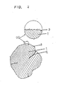
- Fig. 2 is a sketch cross-sectional drawing of a hydrogen-occlusion-alloy powder obtained according to the present invention;
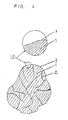
- Fig. 3 is a cross-sectional view showing a structure in which a sponge-like nickel porous body is filled with the alloy powder according to the present invention;
- Fig. 4 is a sketch cross-sectional drawing of the hydrogen-occlusion-alloy powder without both acid and alkali treatments;
- Fig. 5 is a schematic drawing showing the structure of the storage battery of this invention;
- Fig. 6 is a graph showing a relation between SF-value of alloys and charge-discharge cycle of batteries in which there are two types of alloys, namely, one type is treated with both acid and alkali according to the present invention and another type is not treated conventionally;
- Fig. 7 is a graph showing a relation between the charge-discharge cycle and temperatures at which electrodes are treated with alkali;
- Fig. 8 is a graph showing a relation between the charge-discharge cycle and immersion time at which electrodes are treated with alkali;
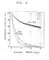
- Fig. 9 is a graph showing a relation between types of separators and degrees of self-discharge; and
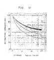
- Fig. 10 is a graph showing a relation between contents of Manganese in alloys and degrees of self-discharge during preservation.
-
- Reffering to Figs. 2 to 6, one embodiment of the present invention will be described hereinbelow. Misch metal (Mm), nickel (Ni), cobalt (Co), aluminum (Al), and manganese (Mn) are mixed in the ratio of the number of atoms as follows:
1 : 3.5 : 0.8 : 0.3 : 0.4 respectively. The misch metal is composed of mainly about 40 wt % of cerium, about 30 wt % of Lanthanium, and about 13 wt % of neodymium. The mixture is melted by using a high-frequency furnace in the atomosphere of inert gas. The mixture is transferred to a container having a cooling apparatus while stirring, and then, the mixture is rapidly cooled. The resulting alloy is roughly crushed with a mechaniacal means. After this, the alloy is heated to 1050 °C in the atomosphere of argon gas and is held at 1050 °C for 3 hours, so that a hydrogen-occlusion-alloy is obtained whose SF-value is 2.5 or below. Next, the alloy is crushed again to fine powder whose diameter is 37 µm or below. The powder is immersed in a dilute nitric acid (1N) for a few minutes, and then, is immersed in a KOH aqueous solution (7N) at 80 °C for 30m minutes. By washing with water and drying, thealloy powder 4 having numerous irregularities in the vicivity of the surface layer whose depth is of approximately 0.01 µm is obtained. Fig. 2 shows a sketch cross-sectional drawing of the hydrogen-occlusion-alloy powder obtained by the above-mentioned operation. In Fig. 2,numeral 1 denotes a portion having a high cristallinity in the powder. On the other hand, numeral 2 denotes a portion having a poor cristallinity where the alooy does not be composed by the above-mentioned compounding ratio when analyzing in detail.Numeral 3 denotes the surface layer of the alloy powder. A portion of (A) of the surface layer is enlarged and is shown in the circle. Not concerning the present invention, the mixture is melted in the high-frequency furnace which mixture composition is equal to that of the above-mentioned mixture of this invention, and then, is cooled as it is, namely, slow coolings. After this, the resulting alloy is mechanically crushed so as to make powder having a diameter of 37 µm or below. Fig. 4 shows a sketch cross-sectional drawing of the resulting powder. The meaning of the numeral in Fig. 4 is the same in Fig. 2. In this case, thisalloy powder 4 is liable to separation due to the difference of the specific gravity of each element, and has many portion where cristallinity is poor. Comparing Fig. 4 with Fig. 2, the alloy in Fig. 2 differs largely from the all in Fig. 4 in that the alloy in Fig. 2 has a higher cristallinity and mere numerous irregularities on the surface layer. The cristallinity of the alloy corresponds to the flattness of equilibrium pressure of hydrogen; namely SF-value, which can be obtained when releasing hydrogen as shown in Fig. 1. Therefore, the cristallinity is generally expressed by SF-value. The smaller the SF-value, the higher the cristallinity even if the material is the same. The SF-value of the alloy in Fig. 4 is 2.7 to 3.4 whereas the SF-value of the alloy in Fig. 2 is 1.5 to 2.5. - A sponge-like nickel porous body that porosity is approximately 93 %, thickness is approximately 0.8 mm, and mean spherical space diameter is 400 µm is filled with a paste-like mixture of the
powder 4 of hydrogen-occlusion-alloy of this embodiment and a 5 wt % aqueous solution of a polyvinyl alcohol, and is dried. The obtained body is pressed, and then is cut, so that the resulting electrode is 0.5 mm thick, 39 mm wide, and 80 mm long, and has a capacitance capable of charge and discharge of 1600 mAh. Fig. 3 shows a rough cross-sectional view of thiselectrode 10. In Fig. 3,numeral 4 denotes alloy powder, numeral 5 denotes a framework of the sponge-like nickel porous body, and numeral 6 denotes a space portion. - The battery system in the present invention is shown in Fig. 5. The battery comprises a casing, a
negative electrode 10, a positive electrode 11, aseparator 12, an electrolyte, a sparator means, a sealing plate, a positive lead, a safety valve, a positive terminal, an insulator, and an insulating gasket. Thenegative electrode 10, theseparator 12, and the positive electrode 11 are important in this invention. Four sheets comprising theseparator 30 sandwiched between the positive electrode 11 and thenegative electrode 10, and the separator means are wound in the form of a roll. The electrolyte is mainly immersed into theseparator 12. Even if the electrolyte is not described in the battery system, the electrolyte of a conventional KOH aqueous solution is used in the battery system hereinafter. A cylindrical sealed storage battery of AA size is constructed by the resultingelectrode 10, a conventional nickel positive electrode 11 of foaming metal type, an electrolyte, and aseparator 12 of a nonwoven fabric of a polypropylene introducing sulfonic acid group and has the capacitance of approximately 1000 mAh. The cycle test of charge and discharge at 20°C has been carried out. Charge is carried out at 100 mA for 15 hours, discharge is carried out at 200 mA to 1.0 V/cell, and life-time is determined by the point where the capacitance decreases to 80 % of the initial capacitance. - Hydrogen-occlusion-alloys of this embodiment are ten times made on an experimental basis, and alloys having following SF-value are selected, i.e. 1.5, 2.0, 2.3 and 2.48. On the other hand, alloys are also made, but these alloys are different from the above-mentioned alloys only in that these alloys are conventionally cooled as it is, namely, slow cooling. In the case of the later method, the alloys take SF-value 2.3 to 3.4, and alloys having following SF-value are selected, i.e. 2.52, 3.0 and 3.38. Fig. 6 shows the result of the cycle test. In Fig. 6, the samples (Aʹ) to (Dʹ) are obtained without acid and alkali treatment, and each point in Fig. 6 is the average of measurements of five storage batteries. SF-value is plotted as abscissa against charge-discharge cycle as ordinate in this figure. The contents of the comparison samples, i.e. (B) to (D) and (Bʹ) to (Dʹ), as well as (A) and (Aʹ) will be described hereinbelow.

alloy powder 4 is treated with both acid and alkali, there is a tendancy for the cycling life-time property to be improved. Especially, when alloys, whose SF-value are 2.5 or below, are treated with both acid and alkali, the cycling life-time property is extremely improved. However, in the case of alloys, i.e. (D) or (Dʹ), containing no cobalt, the degree of the improvement in the above-mentioned property is small. From these results, it seems that the acid and alkali treatments mainly elute cobalt so that irregularity on the surface of thealloy powder 4 is formed. Moreover, although the combination of both acid and alkali treatments shows an effect, the same result can be obtained even when acid treatment or alkali treatment is carried out independently for a given long time. - Therefore, in the
electrode 10 where the negative electrode material is the hydrogen-occlusion-alloy mainly composed of misch metal and nickel and utilizing at least cobalt as an element to be displaced, the sealed storage battery having a long life-time can be obtained although oxidation is drastic in this battery, by the method that SF-value of the alloy material is 2.5 or below, cobalt is eluted, and lanthanium series metals and nickel are contained relatively at high ratio. - In this embodiment, alloy materials have been described whose basic form is MmNi₅ of Ca₅Cu₅ type. However, alloy materials indicated by MmNi4.7-5.3 of familiar type also have the crystal structure of CaCu₅ type, and show a similar tendency concerning the life-time property.
- The powder is treated in the process of both acid and alkali treatments of this embodiment. However, in the state of pole plate where the sponge-like nickel porous body is filled with the paste-like mixture and then is cried, even if both acid and alkali treatments are carried out as well, the improvement of the cycling life-time has been recognized, and the same result has been obtained. The battery system is constructed by utilizing a silver oxide as the positive electrode 11 instead of the nickel oxide, and then the cycling life-time is examined. The cycling life-time is improved and the silver oxide as well as the nickel oxide is effectual, owing to the fact that SF-value of the alloy material of the
negative electrode 10 is 2.5 or below, and irregularity on the surface is formed by both acid and alkali treatments. Therefore, as the positive electrode 11, metal oxides can be used which is utilized as the active material for the possitive electrode 11 of the alkaline storage battery. - Moreover, with the battery system being constructed by using the material of (A) and the three types of
separators 12, the amount of self-discharge is examined after the battery is fully charged and then leaves as it is at 45°C for a month.First separator 12 is made of a nonwoven fabric of a polyamide,second separator 12 is made of a nonwoven fabric of a polypropylene where surfactants are added so as to improve hydrophilic property, andthird sepsrator 12 is made of a nonwoven fabric of a polypropylene introducing sulfonic acid group. In thethird separator 12, 55 to 60% of discharge capacitance is maintained in comparison with the discharge capacitance before the presrvation whereas discharge capacitance is not practically detected in thefirst separator 12 and thesecond separator 12. It is effectual to use theseparator 12 which is made of the nonwoven fabric of the polypropylene introducing sulfonic acid group in order to decrease the self-discharge. - Another embodiment of the present invention will be described hereinbelow. An alloy is melted by using a high-frequency furnace in the atmosphere of inert gas. The alloy has the composition of Mm Ni3.5 Co0.8 Al0.3 Mn0.4 which composition is the same as that of the hydrogen-occlusion-alloy shown in the first embodiment. The alloy obtained by the method of the rapid cooling is heated in the atmosphere of argon gas, and then , without acid and alkali treatments, is crushed to make fine powder whose diameter is 37 µm or below.
- The resulting powder is mixed with a 5wt% aqueous solution of a polyvinyl alcohol so as to make a paste-like mixture. Then, a sponge-like nickel porous body is filled with the paste-like mixture, and is dried in the same manner as the first embodiment. After this, the electrode is immersed in a KoH aqueous solution (specific gravity is 1.30) for 12 hours. At this time, temperature is varied as follows: 30, 45, 50, 60, 80, and 100°C. Then, hydrogen-occlusion-electrodes as
negative electrodes 10 are obtianed, by washing, drying, and pressing. The surface is magnified and observed by a microscope with thealloy powder 4 of the resulting hydrogen-occlusion-alloy being separated. As a result, irregularity in the vicinity of the surface is recognized as shown in Fig. 2, although there is a difference caused by the difference of the immersin temperature. - By cutting the resulting electrodes, the hydrogen-occlusion-electrodes having a length of 80 mm and a width of 39 mm are obtained. These
electrodes 10 have a capacitance capable of charge and discharge of 1600 mAh or above. A cylindrical sealed battery of AA size is constructed by the combination of thiselectrode 10 and a conventional nickel positive electrode 11 of foaming metal tye, and this battery has a capacitance of approximately 1000 mAh. The cycle test of charge and discharge at 20°C has been carried out. The charge is carried out at 100 mA fo 15 hours, and the discharge is carried out at 200 mA to 1.0 V/cell. The battery constructing conditions are shown below, and the result of the cycle test of charge and discharge is shown in Fig. 7.
- On the other hand, the relationship between the cycling life-time and the immersion time in a KOH aqueous solution (specific gravity is 1.3) is shown in Fig. 8. In this figure, the cycling life-time is represented by the number of cycles of charge-discharge where the capacitance decreases to 80% of the initial capacitance. As is apparent from Fig. 8, the electrode can be immersed in the alkaline solution for 0.2 to 24 hours, when the battery is obtained which has the property of the cycling life-time more than 200 cycles. Moreover, the
electrode 10 can be immersed in the alkaline solution for 1.0 to 12 hours, when the battery is obtained which has the property of the cycling life-time more than 400 cycles. - As described above, even if the sponge-like nickel porous body is filled with the paste-like mixture of the
alloy powder 4 and the 5 wt% aqueous solution of polyvinyl alcohl, is dried, and then, is immersed in the alkaline solution, numerous irregularities in the vicinity of the surface of the alloy is formed so that this method also has an effect on the property of the long life-time of the battery. It has a good effect on theelectrode 10 that the alkaline solution is held at 50 to 100°C and is maintained for 0.2 to 24 hours. More preferably, it has a better effect that the alkaline solution is held at 50 to 80°C and is maintained for 1 to 12 hours. Although in this embodiment, the alkaline solution with a specific gravity of 1.3 is applied, experiments are additionally made in the same manner using the alkaline solutions with a specific gravity of 1.05 to 1.45. From the result of the experiments, since alkaline solution with a small specific gravity has a few effects, it is necessary for the electrode to be immersed in the alkaline solution for a long time in this case. Therefore, the alkaline solution with a specific gravity of 1.1 or above has a sufficient effect on theelectrode 10. - The other embodiment of the present invention will be described hereinbelow. This embodiment relates the battery system which is capable of the decrease of the self-discharge. The alloy to be utilized as the
negative electrode 10 is produced in the same manner as first embodiment. The composition of the alloy is represented as following formula.
Mm Ni3.95-x Mnx Al0.3 Co0.75.
In this case, the amount of Ni and Mn is varied, namely, value of X is changed as follows: 0, 0.2, 0.3, 0.4, 0.6, and 0.8. As a result, six kinds of alloys whose compositions are different are obtained. These six kinds of alloys are milled with a ball mill so as to make powder having a diameter of 37 µm or below. After this, in the same manner as second embodiment, the sponge-like nickel body is filled with the paste-like mixture of thealloy powder 4 and the 5 wt% aqueous solution of the polyvinyl alcohol, is dried, and then, the resulting material is immersd in the KOH aqueous solution with a specific gravity of 1.3 at 80 °C for 12 hours, is washed with water, is dried, and then, is pressed so that thenegative electrode 10 is obtained. - In this case, three kinds of separators are utilized; that is,
first separator 12 is made of the nonwoven fabric of polyamide,second separator 12 is made of the nonwoven fabric of the polypropylene where surfactants are added so as to improve hydrophilic property, andthird separator 12 is the nonwoven fabric of the polypropylene introducing sulfanic acid group. - Although various methods for introducing sulfonic acid group are contrived, the following method is adopted. The nonwoven fabric of the polypropylene is immersed in 20% solution of fuming sulfuric acid for a given period of time so as to introduce sulfonic acid group to the polypropylene. After this, the fabric is immersed in various concentrations of sulfuric acid in order, that is, first step 90%, second step 60%, and
third step 30%. Lastly, the residual sulfuric acid is removed by washing with water, and then, the fabric is dried. The resulting fabric is used as the sulfonated separator. In this case, the amount of sulfonic acid gruop to be introduced can be varied by the method of varying the time for immersing in the fuming sulfuric acid. In this embodiment, the degree of sulfonation is measured with the immersion time being varied from 10 to 90 minutes. From this result, N-value is destributed from 20 to 250. N-value means the number of monomers in the polypropylene to which one sulfonic acid group is introduced. The sealed nickel-hydrogen storage batteries of AA size, i.e. (F-1) to (F-13), having a discharge capacitace of approximately 1000 mAh are assembled by combinig theseseparators 12, the six kinds of the hydrogen-occlusion-electrodes described above, and the conventonal nickel positive electrode 11 of foaming metal type as shown in Table 1.
- The self-discharge is measured as described below. The charge is carried out at charging rate of 0.1 CmA to 150% relative to a nominal capacitance of 1000 mAh, and the discharge is continued at 0.2 CmA until the voltage becomes 1.0 V at 20°C. Both the charge and discharge are repeated twenty times on the same condition described above, and then, the charge is carried out in the same manner as described above. Next, the batteries are maintained at 45°C for a given period of time after charging. Then, the discharge capacitance is measured in such a way that the discharge is carried out at the discharging rate of 0.2 CmA until the voltage becomes 1V at 20°C. From these results, retention capacity is calculated by comparing the resulting discharge capacitance with the discharge capacitance before preservation. In Fig. 9, storage period is plotted as abscissa against the retention capacity as ordinate concerning (F-1) to (F-6), (F-12), and (F-13). As is apparent from Fig. 9, when battery (F-12) applying the fabric of the polyamide to the
separator 12 and battery (F-13) applying the fabric of the polypropylene where surfactants are added are preserved at 45°C for 30 days, the retention capacity becomes 0%, namely, the degree of the self-discharge is 100%. - On the contrary, batteries (F-1) to (F-6) using separators where N-values are 20 to 250, show an excellent effect. Namely, even if batteries are maintained at 45°C for 30 days, the retention capacity is 55 to 60%. However, when the battery is constructed by utilizing the
separator 12 made of the fabric of the polypropylene (N-value = 20), short phenomenon arises between the positive electrode 11 and thenegative electrode 10 in proportion of one to four. This is because the increment of the sulfonic acid group causes the strength of theseparator 12 to decrease. Moreover, when theseparator 12 made of the fabric of the polypropylene (N-value = 250 or above) is applied to the battery, the time for injecting the electrolyte on constructing the battery is increased and the cycling life-time of the battery is decreased. This is because the amount of sulfonic acid groups become extremely smaller. As a result, it became clear that the optimal N-value is 20 to 250. - Fig. 10 shows that the property of the self-discharge is varied, when the component of the alloys is varied with the degree of sulfonation being fixed. As is apparent from Fig. 10, although the retention capacity of the battery (F-7) utilizing alloy without containing Mn is superior to that of the batteries (F-12) and (F-13) shown in Fig. 9, the retention capacity is 40% or below when maintaining for 30 days. However, when x is 0.2 or above in the formula of alloy, the retention capacity is 40% or above after maintaining for 30 days. However, when x is 0.8 or above in the formula of alloy, equlibrium dissocation pressure of the hydrogen-occlusion-alloy decreases and the discharge capacitance becomes small. As a result, it is difficult to designe of the battery having a high capacitance.
- In this embodiment, the nonwoven fabric of the polypropylene having the porosity of 65% is used. However, when the battery is constructed by utilizing the nonwoven fabric of the sulfonated polypropylene having the porosity of 70% or above, the strength of the
separator 12 decreases and short phenomenon arises. On the other hand, when the sulfonated polypropylene having the porosity of 40% or below as theseparator 12 is used, the penetrating velocity of oxygen generated at the positive electrode 11 on overcharging through theseparator 12 decreases, and the electrolyte into theseparator 12 increases. Therefore, the absorptivity of oxygen gas on the surface of thenegative electrode 10 decreases so that the increment of the pressure in the battery or the leakage of the electrolyte arises. As a result, the porosity of 40 to 70% is suitable for the sulfonated separator. - Moreover, polypropylene resin is used as one example of a polyolefine resin in this embodiment. However, the same result can be obtained even if polyethylene resin is used. Sulfonation is carried out by fuming sulfuric acid in this embodiment. However, the same result can be obtained by limiting the degree of sulfonation as described above, even if the other sulfonating agents such as heated concentrated sulfuric acid or sulfur trioxide are used. As a result, this technique can be widely used by limiting the degree of sulfonation.
- The above-described embodiments are just examples of the present invention, and therefore, it will be apparent for those skilled in the art that many modifications and variations may be made without departing from the spirit of the present invention.
- A sealed storage battery comprises a positive electrode (11) including a metallic oxide as an active material, a negative electrode (10) including hydrogen-occlusion-alloy powder (4) capable of charging and discharging electrochemically hydrogen as an active material, an alkaline electrolyte, and a separator (12) for absorbing and holding the alkaline electrolyte. The hydrogen-occlusion-alloy powder (4) has a crystal structure of CaCu₅ type, is provided with numerous irregularities on the surface thereof, and has SF-value of 2.5 or below, which SF-value represents a plateau characteristic of equilibrium pressure of hydrogen releasing. The numerous irregularities on the surface of the alloy powder (4) causes oxygen being generated from the positive electrode (11) to be eliminated promptly.
Claims (13)
forming a hydrogen-occlusion-electrode by a metallic porous body being filled with hydrogen-occlusion-alloy power; and
forming fine irregularities on a surface layer of sid hydrogen-occlusion-alloy by immersing said hydrogen-occlusion-electrode in an acid solution or an akaline solution so as to elute a part of alloy components.
Applications Claiming Priority (8)
| Application Number | Priority Date | Filing Date | Title |
|---|---|---|---|
| JP291832/86 | 1986-12-08 | ||
| JP61291830A JPH0756800B2 (en) | 1986-12-08 | 1986-12-08 | Method for manufacturing hydrogen storage electrode |
| JP291830/86 | 1986-12-08 | ||
| JP61291832A JPH0756801B2 (en) | 1986-12-08 | 1986-12-08 | Method for manufacturing hydrogen storage electrode |
| JP210468/87 | 1987-08-25 | ||
| JP62210468A JP2532498B2 (en) | 1987-08-25 | 1987-08-25 | Hydrogen storage alloy electrode |
| JP62212089A JP2733227B2 (en) | 1987-08-26 | 1987-08-26 | Nickel-metal hydride battery |
| JP212089/87 | 1987-08-26 |
Publications (2)
| Publication Number | Publication Date |
|---|---|
| EP0271043A1 true EP0271043A1 (en) | 1988-06-15 |
| EP0271043B1 EP0271043B1 (en) | 1992-01-22 |
Family
ID=27476499
Family Applications (1)
| Application Number | Title | Priority Date | Filing Date |
|---|---|---|---|
| EP87118066A Expired - Lifetime EP0271043B1 (en) | 1986-12-08 | 1987-12-07 | Sealed storage battery and method for making its electrode |
Country Status (3)
| Country | Link |
|---|---|
| US (1) | US4837119A (en) |
| EP (1) | EP0271043B1 (en) |
| DE (1) | DE3776300D1 (en) |
Cited By (19)
| Publication number | Priority date | Publication date | Assignee | Title |
|---|---|---|---|---|
| EP0273625A2 (en) * | 1986-12-29 | 1988-07-06 | Energy Conversion Devices, Inc. | A method of making a sealed rechargeable hydrogen storage cell |
| EP0386305A1 (en) * | 1989-02-23 | 1990-09-12 | Matsushita Electric Industrial Co., Ltd. | Alkaline storage battery and method of producing negative electrode thereof |
| FR2654262A1 (en) * | 1989-11-07 | 1991-05-10 | Accumulateurs Fixes | METHOD FOR COVERING AN ELECTRODE WITH A FOAM SUPPORT FOR AN ELECTROCHEMICAL GENERATOR AND ELECTRODE OBTAINED BY THIS METHOD. |
| EP0432342A1 (en) * | 1989-12-13 | 1991-06-19 | Matsushita Electric Industrial Co., Ltd. | Rectangular sealed alkaline storage battery with negative electrode comprising hydrogen storage alloy |
| EP0451575A1 (en) * | 1990-03-24 | 1991-10-16 | Japan Storage Battery Company Limited | Hydrogen absorbing electrode for use in nickel-metal hydride secondary batteries |
| US5250369A (en) * | 1989-02-23 | 1993-10-05 | Matsushita Electric Industrial Co., Ltd. | Alkaline storage battery |
| US5346781A (en) * | 1989-02-23 | 1994-09-13 | Matsushita Electric Industrial Co., Ltd. | Alkaline storage battery |
| US5348823A (en) * | 1989-11-07 | 1994-09-20 | Saft S.A. | Process of preparing an electrode for an electrochemical cell with a porous support and an electrode obtained by said process |
| EP0627779A1 (en) * | 1993-05-31 | 1994-12-07 | SANYO ELECTRIC Co., Ltd. | Sealed type nickel-metal hydride alkaline storage cell |
| EP0645833A1 (en) * | 1993-08-31 | 1995-03-29 | SANYO ELECTRIC Co., Ltd. | Method for producing a hydrogen absorbing alloy electrode |
| EP0650207A1 (en) * | 1993-10-25 | 1995-04-26 | Furukawa Denchi Kabushiki Kaisha | A preparing method for a nickel hydroxide for a nickel electrode, a manufacturing method for the nickel electrode, and an alkaline secondary battery incorporating the nickel electrode therein |
| EP0696823A1 (en) * | 1994-02-25 | 1996-02-14 | Yuasa Corporation | Hydrogen absorbing electrode and production method thereof |
| US5738958A (en) * | 1995-07-27 | 1998-04-14 | Varta Batterie Aktiengesellschaft | Alloys for use as active material for the negative electrode of an alkaline, rechargeable nickel-metal hydride battery, and process for its production |
| US5738953A (en) * | 1995-04-06 | 1998-04-14 | Varta Batterie Aktiengesellschaft | Alkaline metal oxide/metal hydride battery |
| EP0944124A1 (en) * | 1998-02-19 | 1999-09-22 | Matsushita Electric Industrial Co., Ltd. | Hydrogen-absorbing alloy for battery, method for producing the same, and alkaline storage battery using the same |
| EP0986119A1 (en) * | 1998-09-11 | 2000-03-15 | Matsushita Electric Industrial Co., Ltd. | Alkaline storage battery, hydrogen-absorbing alloy electrode and method for producing the same |
| EP1111700A2 (en) * | 1999-11-04 | 2001-06-27 | Matsushita Electric Industrial Co., Ltd. | Alkaline storage battery |
| EP1179868A1 (en) * | 2000-08-10 | 2002-02-13 | Alcatel | Hydridable alloy |
| US6777129B2 (en) | 2000-04-27 | 2004-08-17 | Matsushita Electric Industrial Co., Ltd. | Alkaline storage battery |
Families Citing this family (19)
| Publication number | Priority date | Publication date | Assignee | Title |
|---|---|---|---|---|
| JP2926734B2 (en) * | 1989-02-23 | 1999-07-28 | 松下電器産業株式会社 | Alkaline storage battery using hydrogen storage alloy |
| JPH02227966A (en) * | 1989-02-28 | 1990-09-11 | Matsushita Electric Ind Co Ltd | Sealed alkaline storage battery and manufacture of its negative electrode |
| DE69014183T2 (en) * | 1989-09-18 | 1995-06-22 | Toshiba Kawasaki Kk | Nickel-metal hydride secondary cell. |
| JPH04137368A (en) * | 1990-09-26 | 1992-05-12 | Matsushita Electric Ind Co Ltd | Nickel-hydrogen storage battery and its manufacture |
| US5487961A (en) * | 1992-04-24 | 1996-01-30 | Eveready Battery Company, Inc. | Sintered metal electrode |
| US5468309A (en) * | 1992-09-14 | 1995-11-21 | Matsushita Electric Industrial Co., Ltd. | Hydrogen storage alloy electrodes |
| JP3438142B2 (en) * | 1992-09-18 | 2003-08-18 | 松下電器産業株式会社 | Medium / large capacity sealed metal oxide / hydrogen storage battery |
| US5523182A (en) * | 1992-11-12 | 1996-06-04 | Ovonic Battery Company, Inc. | Enhanced nickel hydroxide positive electrode materials for alkaline rechargeable electrochemical cells |
| JPH06283163A (en) * | 1993-03-30 | 1994-10-07 | Furukawa Battery Co Ltd:The | Manufacture of hydrogen storage alloy electrode |
| US5695530A (en) * | 1994-03-14 | 1997-12-09 | Hong; Kuochih | Method for making high charging efficiency and fast oxygen recombination rechargeable hydride batteries |
| JP3318141B2 (en) * | 1994-04-04 | 2002-08-26 | 松下電器産業株式会社 | Method for producing hydrogen storage alloy electrode |
| DE69701411T2 (en) * | 1996-02-02 | 2000-07-06 | Matsushita Electric Ind Co Ltd | Batteries and method of making a positive active material |
| JP3214341B2 (en) * | 1996-03-08 | 2001-10-02 | 松下電器産業株式会社 | Manufacturing method of hydrogen storage alloy for batteries |
| US6197448B1 (en) | 1997-05-30 | 2001-03-06 | Duracell Inc. | Hydrogen storage alloy |
| US5865874A (en) * | 1997-06-27 | 1999-02-02 | Duracell Inc. | Hydrogen storage alloy |
| JP3429741B2 (en) * | 2000-03-24 | 2003-07-22 | 松下電器産業株式会社 | Paste positive electrode for alkaline storage batteries and nickel-metal hydride storage batteries |
| JP2002313306A (en) * | 2001-04-06 | 2002-10-25 | Isao Matsumoto | Manufacturing method of separator for use in battery, separator for use in battery and alkaline storage battery using it |
| US7960065B2 (en) * | 2005-06-21 | 2011-06-14 | Dainippon Ink And Chemicals, Inc. | Separator for fuel cell, method for producing the same, and fuel cell |
| JP6555212B2 (en) | 2016-08-15 | 2019-08-07 | トヨタ自動車株式会社 | Battery pack manufacturing method |
Citations (2)
| Publication number | Priority date | Publication date | Assignee | Title |
|---|---|---|---|---|
| EP0170519A2 (en) * | 1984-07-31 | 1986-02-05 | Kabushiki Kaisha Toshiba | A method of producing a sealed metal oxide-hydrogen storage cell |
| GB2162994A (en) * | 1984-08-10 | 1986-02-12 | Sanyo Electric Co | Metal/hydrogen alkaline storage battery |
Family Cites Families (7)
| Publication number | Priority date | Publication date | Assignee | Title |
|---|---|---|---|---|
| JPS59181459A (en) * | 1983-03-31 | 1984-10-15 | Toshiba Corp | Metal oxide hydrogen battery |
| JPS61101957A (en) * | 1984-10-24 | 1986-05-20 | Agency Of Ind Science & Technol | Hydrogen occluding electrode and its manufacturing method |
| JPS61176063A (en) * | 1985-01-29 | 1986-08-07 | Matsushita Electric Ind Co Ltd | Manufacture of alkaline battery |
| US4716088A (en) * | 1986-12-29 | 1987-12-29 | Energy Conversion Devices, Inc. | Activated rechargeable hydrogen storage electrode and method |
| US5254500A (en) * | 1991-02-05 | 1993-10-19 | Advanced Micro Devices, Inc. | Method for making an integrally molded semiconductor device heat sink |
| JPH06147075A (en) * | 1992-11-17 | 1994-05-27 | Nippon Carbureter Co Ltd | Engine ignition timing control method |
| JPH06164069A (en) * | 1992-11-25 | 1994-06-10 | Fujitsu Ltd | Semiconductor laser |
-
1987
- 1987-12-07 DE DE8787118066T patent/DE3776300D1/en not_active Expired - Lifetime
- 1987-12-07 EP EP87118066A patent/EP0271043B1/en not_active Expired - Lifetime
- 1987-12-08 US US07/132,647 patent/US4837119A/en not_active Expired - Lifetime
Patent Citations (2)
| Publication number | Priority date | Publication date | Assignee | Title |
|---|---|---|---|---|
| EP0170519A2 (en) * | 1984-07-31 | 1986-02-05 | Kabushiki Kaisha Toshiba | A method of producing a sealed metal oxide-hydrogen storage cell |
| GB2162994A (en) * | 1984-08-10 | 1986-02-12 | Sanyo Electric Co | Metal/hydrogen alkaline storage battery |
Non-Patent Citations (2)
| Title |
|---|
| CHEMICAL ABSTRACTS, Vol. 106, No. 1, January 5, 1987, Columbus, Ohio, USA FURUKAWA, SANEHIRO et al. "Hydrogen Absorbing Anode" page 151, column 1, Abstract-No. 7 556b & Jpn. Kokai Tokkyo Koho JP 61 168 871 * |
| CHEMICAL ABSTRACTS, Vol. 106, No. 1, January 5, 1987, Columbus, Ohio, USA FURUKAWA, SANEHIRO et al. "Metalhydrogen Alkaline Battery" page 151, column 1, Abstract-No. 7 557c & Jpn. Kokai Tokkyo Koho JP 61 168 870 * |
Cited By (36)
| Publication number | Priority date | Publication date | Assignee | Title |
|---|---|---|---|---|
| EP0273625A3 (en) * | 1986-12-29 | 1989-06-14 | Energy Conversion Devices, Inc. | Activated rechargeable hydrogen storage electrode and method |
| EP0273625A2 (en) * | 1986-12-29 | 1988-07-06 | Energy Conversion Devices, Inc. | A method of making a sealed rechargeable hydrogen storage cell |
| US5034289A (en) * | 1989-02-23 | 1991-07-23 | Matsushita Electric Industrial Co., Ltd. | Alkaline storage battery and method of producing negative electrode thereof |
| EP0386305A1 (en) * | 1989-02-23 | 1990-09-12 | Matsushita Electric Industrial Co., Ltd. | Alkaline storage battery and method of producing negative electrode thereof |
| US5346781A (en) * | 1989-02-23 | 1994-09-13 | Matsushita Electric Industrial Co., Ltd. | Alkaline storage battery |
| US5250369A (en) * | 1989-02-23 | 1993-10-05 | Matsushita Electric Industrial Co., Ltd. | Alkaline storage battery |
| EP0427141A1 (en) * | 1989-11-07 | 1991-05-15 | SAFT (inscrite au Registre du Commerce sous le numéro 343 588 737) | Method for covering an electrode with a sponge like support for electrochemical generator and electrode obtained by this process |
| US5348823A (en) * | 1989-11-07 | 1994-09-20 | Saft S.A. | Process of preparing an electrode for an electrochemical cell with a porous support and an electrode obtained by said process |
| FR2654262A1 (en) * | 1989-11-07 | 1991-05-10 | Accumulateurs Fixes | METHOD FOR COVERING AN ELECTRODE WITH A FOAM SUPPORT FOR AN ELECTROCHEMICAL GENERATOR AND ELECTRODE OBTAINED BY THIS METHOD. |
| EP0432342A1 (en) * | 1989-12-13 | 1991-06-19 | Matsushita Electric Industrial Co., Ltd. | Rectangular sealed alkaline storage battery with negative electrode comprising hydrogen storage alloy |
| EP0451575A1 (en) * | 1990-03-24 | 1991-10-16 | Japan Storage Battery Company Limited | Hydrogen absorbing electrode for use in nickel-metal hydride secondary batteries |
| US5284619A (en) * | 1990-03-24 | 1994-02-08 | Japan Storage Battery Company, Limited | Hydrogen absorbing electrode for use in nickel-metal hydride secondary batteries |
| EP0627779A1 (en) * | 1993-05-31 | 1994-12-07 | SANYO ELECTRIC Co., Ltd. | Sealed type nickel-metal hydride alkaline storage cell |
| CN1076888C (en) * | 1993-05-31 | 2001-12-26 | 三洋电机株式会社 | Sealed type nickel metal hydrogen alkaline storage cell |
| US5518509A (en) * | 1993-08-31 | 1996-05-21 | Sanyo Electric Co., Ltd. | Method for producing a hydrogen absorbing alloy electrode |
| EP0645833A1 (en) * | 1993-08-31 | 1995-03-29 | SANYO ELECTRIC Co., Ltd. | Method for producing a hydrogen absorbing alloy electrode |
| US5549992A (en) * | 1993-10-25 | 1996-08-27 | Furukawa Denchi Kabushiki Kaisha | Preparing method for a nickel hydroxide for a nickel electrode, a manufacturing method for the nickel electrode, and an alkaline secondary battery incorporating the nickel electrode therein |
| EP0650207A1 (en) * | 1993-10-25 | 1995-04-26 | Furukawa Denchi Kabushiki Kaisha | A preparing method for a nickel hydroxide for a nickel electrode, a manufacturing method for the nickel electrode, and an alkaline secondary battery incorporating the nickel electrode therein |
| EP0696823A1 (en) * | 1994-02-25 | 1996-02-14 | Yuasa Corporation | Hydrogen absorbing electrode and production method thereof |
| US5935732A (en) * | 1994-02-25 | 1999-08-10 | Yuasa Corporation | Hydrogen absorbing electrode and its manufacturing method |
| EP0696823A4 (en) * | 1994-02-25 | 1996-04-24 | Yuasa Battery Co Ltd | Hydrogen absorbing electrode and production method thereof |
| US5738953A (en) * | 1995-04-06 | 1998-04-14 | Varta Batterie Aktiengesellschaft | Alkaline metal oxide/metal hydride battery |
| SG101413A1 (en) * | 1995-04-06 | 2004-01-30 | Treibacher Auermet Prod Gmbh | Alkaline metal oxide/metal hydride battery |
| US5738958A (en) * | 1995-07-27 | 1998-04-14 | Varta Batterie Aktiengesellschaft | Alloys for use as active material for the negative electrode of an alkaline, rechargeable nickel-metal hydride battery, and process for its production |
| EP0944124A1 (en) * | 1998-02-19 | 1999-09-22 | Matsushita Electric Industrial Co., Ltd. | Hydrogen-absorbing alloy for battery, method for producing the same, and alkaline storage battery using the same |
| US6740450B2 (en) | 1998-02-19 | 2004-05-25 | Matsushita Electric Industrial Co., Ltd. | Hydrogen-absorbing alloy for battery, method for producing the same, and alkaline storage battery using the same |
| US6331367B1 (en) | 1998-09-11 | 2001-12-18 | Matsushita Electric Industrial Co., Ltd. | Alkaline storage battery hydrogen-absorbing alloy electrode and method for producing the same |
| US6699617B2 (en) | 1998-09-11 | 2004-03-02 | Matsushita Electric Industrial Co., Ltd. | Alkaline storage battery, hydrogen-absorbing alloy electrode and method for producing the same |
| EP0986119A1 (en) * | 1998-09-11 | 2000-03-15 | Matsushita Electric Industrial Co., Ltd. | Alkaline storage battery, hydrogen-absorbing alloy electrode and method for producing the same |
| EP1111700A3 (en) * | 1999-11-04 | 2002-10-09 | Matsushita Electric Industrial Co., Ltd. | Alkaline storage battery |
| US6605387B1 (en) | 1999-11-04 | 2003-08-12 | Matsushita Electric Industrial Co., Ltd. | Alkaline storage battery |
| EP1111700A2 (en) * | 1999-11-04 | 2001-06-27 | Matsushita Electric Industrial Co., Ltd. | Alkaline storage battery |
| US6777129B2 (en) | 2000-04-27 | 2004-08-17 | Matsushita Electric Industrial Co., Ltd. | Alkaline storage battery |
| EP1179868A1 (en) * | 2000-08-10 | 2002-02-13 | Alcatel | Hydridable alloy |
| FR2812887A1 (en) * | 2000-08-10 | 2002-02-15 | Cit Alcatel | HYDRURABLE ALLOY |
| US6472102B2 (en) | 2000-08-10 | 2002-10-29 | Alcatel | Hydridable alloy |
Also Published As
| Publication number | Publication date |
|---|---|
| US4837119A (en) | 1989-06-06 |
| EP0271043B1 (en) | 1992-01-22 |
| DE3776300D1 (en) | 1992-03-05 |
Similar Documents
| Publication | Publication Date | Title |
|---|---|---|
| US4837119A (en) | Sealed storage battery and method for making its electrode | |
| EP0504949B1 (en) | Hydrogen storage electrode | |
| EP0587974B1 (en) | Sealed metal oxide-hydrogen storage battery | |
| EP0477461B2 (en) | Nickel/hydrogen storage battery and method of manufacturing the same | |
| JPS62139255A (en) | Manufacture of hydrogen absorbing electrode | |
| JPH1074536A (en) | Sealed nickel-hydrogen storage battery | |
| JP2001076730A (en) | Nickel-hydrogen secondary battery | |
| EP0696822B1 (en) | Sealed type alkaline battery | |
| US5131920A (en) | Method of manufacturing sealed rechargeable batteries | |
| JPS62115657A (en) | Sealed nickel-hydrogen storage battery | |
| JP4497828B2 (en) | Nickel-hydrogen storage battery and battery pack | |
| US6197448B1 (en) | Hydrogen storage alloy | |
| JPH08264174A (en) | Hydrogen storage alloy cathode and its preparation | |
| JPH02250260A (en) | Hydrogen storage electrode and manufacture thereof | |
| JP2010010097A (en) | Method of manufacturing nickel metal hydride storage battery | |
| JP3625655B2 (en) | Hydrogen storage alloy electrode and nickel metal hydride storage battery | |
| JP2679441B2 (en) | Nickel-metal hydride battery | |
| JP3266153B2 (en) | Manufacturing method of sealed alkaline storage battery | |
| JP3746086B2 (en) | Method for manufacturing nickel-metal hydride battery | |
| JP2857148B2 (en) | Construction method of sealed nickel-hydrogen storage battery | |
| JPS60220556A (en) | Manufacturing method of hydrogen occluding electrode for enclosed storage battery | |
| JP3070081B2 (en) | Sealed alkaline storage battery | |
| JPH03295177A (en) | Sealed alkaline storage battery | |
| JPH09129227A (en) | Nickel-hydrogen storage battery | |
| JPH0582127A (en) | Enclosed type nickel-metal hydride storage battery |
Legal Events
| Date | Code | Title | Description |
|---|---|---|---|
| PUAI | Public reference made under article 153(3) epc to a published international application that has entered the european phase |
Free format text: ORIGINAL CODE: 0009012 |
|
| 17P | Request for examination filed |
Effective date: 19871207 |
|
| AK | Designated contracting states |
Kind code of ref document: A1 Designated state(s): DE FR GB NL |
|
| 17Q | First examination report despatched |
Effective date: 19900213 |
|
| GRAA | (expected) grant |
Free format text: ORIGINAL CODE: 0009210 |
|
| AK | Designated contracting states |
Kind code of ref document: B1 Designated state(s): DE FR GB NL |
|
| REF | Corresponds to: |
Ref document number: 3776300 Country of ref document: DE Date of ref document: 19920305 |
|
| ET | Fr: translation filed | ||
| PLBI | Opposition filed |
Free format text: ORIGINAL CODE: 0009260 |
|
| 26 | Opposition filed |
Opponent name: EVEREADY BATTERY COMPANY Effective date: 19921023 Opponent name: ALCATEL ALSTHOM CIE.GEN. D ELECTRICITE Effective date: 19921015 |
|
| PLAB | Opposition data, opponent's data or that of the opponent's representative modified |
Free format text: ORIGINAL CODE: 0009299OPPO |
|
| NLR1 | Nl: opposition has been filed with the epo |
Opponent name: EVEREADY BATTERY COMPANY. Opponent name: ALCATEL ALSTHOM CIE.GEN.D ELECTRICITE. |
|
| R26 | Opposition filed (corrected) |
Opponent name: ALCATEL ALSTHOM CIE.GEN. D ELECTRICITE * 921023 EV Effective date: 19921015 |
|
| PLAB | Opposition data, opponent's data or that of the opponent's representative modified |
Free format text: ORIGINAL CODE: 0009299OPPO |
|
| R26 | Opposition filed (corrected) |
Opponent name: ALCATEL ALSTHOM CIE.GEN. D ELECTRICITE * 921023 EV Effective date: 19921015 |
|
| NLR1 | Nl: opposition has been filed with the epo |
Opponent name: EVEREADY BATTERY COMPANY Opponent name: ALCATEL ALSTHOM CIE.GEN. D ELECTRICITE |
|
| PGFP | Annual fee paid to national office [announced via postgrant information from national office to epo] |
Ref country code: FR Payment date: 19961211 Year of fee payment: 10 |
|
| PGFP | Annual fee paid to national office [announced via postgrant information from national office to epo] |
Ref country code: DE Payment date: 19961216 Year of fee payment: 10 |
|
| PLBQ | Unpublished change to opponent data |
Free format text: ORIGINAL CODE: EPIDOS OPPO |
|
| PLAB | Opposition data, opponent's data or that of the opponent's representative modified |
Free format text: ORIGINAL CODE: 0009299OPPO |
|
| R26 | Opposition filed (corrected) |
Opponent name: ALCATEL ALSTHOM COMPAGNIE GENERALE D' ELECTRICITE Effective date: 19921015 |
|
| NLR1 | Nl: opposition has been filed with the epo |
Opponent name: EVEREADY BATTERY COMPANY Opponent name: ALCATEL ALSTHOM COMPAGNIE GENERALE D' ELECTRICITE |
|
| PGFP | Annual fee paid to national office [announced via postgrant information from national office to epo] |
Ref country code: GB Payment date: 19971128 Year of fee payment: 11 |
|
| APAC | Appeal dossier modified |
Free format text: ORIGINAL CODE: EPIDOS NOAPO |
|
| RDAG | Patent revoked |
Free format text: ORIGINAL CODE: 0009271 |
|
| STAA | Information on the status of an ep patent application or granted ep patent |
Free format text: STATUS: PATENT REVOKED |
|
| PGFP | Annual fee paid to national office [announced via postgrant information from national office to epo] |
Ref country code: NL Payment date: 19971223 Year of fee payment: 11 |
|
| 27W | Patent revoked |
Effective date: 19971105 |
|
| GBPR | Gb: patent revoked under art. 102 of the ep convention designating the uk as contracting state |
Free format text: 971105 |
|
| NLR2 | Nl: decision of opposition | ||
| APAH | Appeal reference modified |
Free format text: ORIGINAL CODE: EPIDOSCREFNO |