EP0267978B1 - Combination sensor for the transcutaneous detection of oxygen and carbon dioxide in blood - Google Patents
Combination sensor for the transcutaneous detection of oxygen and carbon dioxide in blood Download PDFInfo
- Publication number
- EP0267978B1 EP0267978B1 EP86115941A EP86115941A EP0267978B1 EP 0267978 B1 EP0267978 B1 EP 0267978B1 EP 86115941 A EP86115941 A EP 86115941A EP 86115941 A EP86115941 A EP 86115941A EP 0267978 B1 EP0267978 B1 EP 0267978B1
- Authority
- EP
- European Patent Office
- Prior art keywords
- light
- sensor
- measuring
- emitting diodes
- sensor according
- Prior art date
- Legal status (The legal status is an assumption and is not a legal conclusion. Google has not performed a legal analysis and makes no representation as to the accuracy of the status listed.)
- Expired - Lifetime
Links
Images
Classifications
-
- A—HUMAN NECESSITIES
- A61—MEDICAL OR VETERINARY SCIENCE; HYGIENE
- A61B—DIAGNOSIS; SURGERY; IDENTIFICATION
- A61B5/00—Measuring for diagnostic purposes; Identification of persons
- A61B5/145—Measuring characteristics of blood in vivo, e.g. gas concentration, pH value; Measuring characteristics of body fluids or tissues, e.g. interstitial fluid, cerebral tissue
- A61B5/14542—Measuring characteristics of blood in vivo, e.g. gas concentration, pH value; Measuring characteristics of body fluids or tissues, e.g. interstitial fluid, cerebral tissue for measuring blood gases
-
- A—HUMAN NECESSITIES
- A61—MEDICAL OR VETERINARY SCIENCE; HYGIENE
- A61B—DIAGNOSIS; SURGERY; IDENTIFICATION
- A61B5/00—Measuring for diagnostic purposes; Identification of persons
- A61B5/145—Measuring characteristics of blood in vivo, e.g. gas concentration, pH value; Measuring characteristics of body fluids or tissues, e.g. interstitial fluid, cerebral tissue
- A61B5/14539—Measuring characteristics of blood in vivo, e.g. gas concentration, pH value; Measuring characteristics of body fluids or tissues, e.g. interstitial fluid, cerebral tissue for measuring pH
-
- A—HUMAN NECESSITIES
- A61—MEDICAL OR VETERINARY SCIENCE; HYGIENE
- A61B—DIAGNOSIS; SURGERY; IDENTIFICATION
- A61B5/00—Measuring for diagnostic purposes; Identification of persons
- A61B5/145—Measuring characteristics of blood in vivo, e.g. gas concentration, pH value; Measuring characteristics of body fluids or tissues, e.g. interstitial fluid, cerebral tissue
- A61B5/1455—Measuring characteristics of blood in vivo, e.g. gas concentration, pH value; Measuring characteristics of body fluids or tissues, e.g. interstitial fluid, cerebral tissue using optical sensors, e.g. spectral photometrical oximeters
- A61B5/14551—Measuring characteristics of blood in vivo, e.g. gas concentration, pH value; Measuring characteristics of body fluids or tissues, e.g. interstitial fluid, cerebral tissue using optical sensors, e.g. spectral photometrical oximeters for measuring blood gases
- A61B5/14552—Details of sensors specially adapted therefor
-
- A—HUMAN NECESSITIES
- A61—MEDICAL OR VETERINARY SCIENCE; HYGIENE
- A61B—DIAGNOSIS; SURGERY; IDENTIFICATION
- A61B5/00—Measuring for diagnostic purposes; Identification of persons
- A61B5/145—Measuring characteristics of blood in vivo, e.g. gas concentration, pH value; Measuring characteristics of body fluids or tissues, e.g. interstitial fluid, cerebral tissue
- A61B5/1468—Measuring characteristics of blood in vivo, e.g. gas concentration, pH value; Measuring characteristics of body fluids or tissues, e.g. interstitial fluid, cerebral tissue using chemical or electrochemical methods, e.g. by polarographic means
- A61B5/1477—Measuring characteristics of blood in vivo, e.g. gas concentration, pH value; Measuring characteristics of body fluids or tissues, e.g. interstitial fluid, cerebral tissue using chemical or electrochemical methods, e.g. by polarographic means non-invasive
Definitions
- the invention relates to a combination sensor for the transcutaneous detection of oxygen (O2) and carbon dioxide (CO2) in the blood.
- Sensors for transcutaneous monitoring of the blood gases O2 and / or CO2 are known.
- sensors also referred to as sensors or sensors for short
- Electric heating has two functions. On the one hand, the warming creates a hyperemia of skin and tissue under the sensor, and on the other hand, keeping the temperature of the sensor constant stabilizes the properties of the physical elements contained in it or electrochemical measuring elements.
- the heating power required to maintain the temperature of the sensor can be used to monitor the relative local blood flow; see.
- the senor In order to avoid skin damage at these temperatures, the sensor must be placed on a different part of the skin surface from time to time; at an operating temperature of 43 ° C approximately every 4 hours. This circumstance requires attention and care by reliable staff, which experience has shown that it cannot be assumed in the home.
- Sensors for transcutaneous monitoring of carbon dioxide (CO2) are described for example in DE-A1-29 11 343 and in DE-A1-32 32 515.
- These sensors contain pH measuring electrodes, which measure the pH in a thin layer of an electrolytic solution, which is closed by a CO2-permeable membrane and is in gas exchange with the material to be measured via CO2 gas diffusion.
- the pH is either measured, as has been known for a long time in blood gas analyzers, with the known glass electrode, e.g. B. in the embodiment according to DE-A1-29 11 343 or more recently with a special iridium-iridium oxide electrode, as described in DE-A1-32 32 515.
- the invention has for its object to provide a combination sensor or combined sensor for simultaneous continuous transcutaneous measurement of carbon dioxide and oxygen in the blood for a long time, for. B. over a day or a night with a single sensor to be monitored without this monitoring having to be interrupted for moving the sensor, for switching over to another sensor or for calibration measures.
- the solution according to the invention is based on the idea of making the possibility of an uninterrupted transcutaneous pCO2 monitoring over a longer period of time usable for a combined transcutaneously measuring oxygen / carbon dioxide sensor in that - in contrast to previously known solutions - a sensor in one pCO2 measuring device is not combined with one for measuring the oxygen partial pressure pO2, but with a measuring device for spectrophotometric measurement of the oxygen saturation of the blood sO2. This initially eliminates the problem of local overheating of the measuring point on the skin, since heating the skin to 43 ° C. or more is no longer necessary.
- the combination sensor for transcutaneous detection of oxygen (O2) and carbon dioxide (CO2) in the blood contains a measuring device for pCO2 with an iridium / iridium oxide measuring electrode and a measuring device for spectrophotometric determination of the oxygen saturation sO2, which consists of a combination of light-emitting Diodes that emit light of different wavelengths and can consist of one or more associated photoelectric receivers.
- the light can also be supplied and removed via light guides, with the spectral light generation and measurement being carried out in the evaluation device.
- the drawing shows an annular housing 4 made of plastic with a central opening 15 into which a metal body 5, preferably made of silver (Ag), is inserted with an exact fit, which in the illustration on the top, ie covering the (later) measuring surface 10 with a silver-silver chloride reference electrode 3 is provided.
- the opening 15 is delimited by a cylindrical wall 21 which protrudes slightly all the way around the surface of the reference electrode 3, so that an electrolyte reservoir 22 is additionally formed due to the edge-side reset of the reference electrode 3.
- the metal body 5, also penetrating the reference electrode 3, has a central bore 12 into which a pH measuring electrode 1 is fitted in a concentric arrangement, which in the preferred embodiment is an iridium / iridium oxide (Ir / IrOx -) electrode which for example, has a diameter of 2 mm.
- This electrode 1 is insulated from the reference electrode 3 and from the metal body 5 by a plastic cast resin layer 2.
- the Ir / IrOx electrode 1 can be produced from a uniform cylindrical piece of iridium which is oxidized on the surface side, ie on the surface facing a membrane 13 and immersed in an electrolyte 8.
- iridium is a comparatively very expensive metal.
- the body of the Ir / IrOx electrode 1 with an iridium plate 11 on the end face, ie on the surface immersed in the electrolyte 8, which plate 11 is in contact with the rest of the electrode body
- iridium plate 11 can consist of silver or copper, is electrically and thermally well connected.
- the surface of the iridium plate 11 which is immersed in the electrolyte 8 is oxidized electrochemically or thermochemically, the oxide also being able to be present in hydrated form as an iridium oxide hydrate.
- the reference electrode 3 is either formed by an at least partially chlorinated surface of the metal body 5 made of silver or is plated onto the metal body 5 as an annular plate made of sintered silver / silver chloride metal.
- the metal body 5 is provided in the region of its circumferential outer surface with an annular circumferential wide groove, in which a heating coil 7 is inserted.
- the heating power supply to the metal body 5 is regulated via at least one temperature sensor, for example a thermistor 23, which is inserted into an eccentric bore 6.
- a further (not shown) temperature sensor in turn, for example a thermistor, can be inserted into the metal body 5, which controls a switch element (not shown) for the immediate interruption of the heating power supply to the heating winding 7 when the temperature in the metal body has a predefinable one Threshold value of, for example, 42 ° C.
- the two light-emitting diode elements 24 and 25 are inserted into a trough-like recess 27 in the layer of Ag / AgCl of the reference electrode 3 or of the metal body 5, which is poured out with a translucent casting compound 28 in a moisture and airtight manner, on the surface side, ie on the Membrane 13 facing measuring surface side, ground flat and polished.
- the translucent potting compound 28 can simultaneously serve as an (additional) passivation layer for the light-emitting diodes 24 and 25.
- the light exit sides of the diodes 24 and 25 are aligned with the layer of the electrolyte 8 present between the measuring surface and the membrane after the completion of the sensor described below in such a way that their rays do not interfere with one another.
- the signal supply to the diodes 24 and 25 takes place via lead wires 29 which pass through a bore 30 in the metal body 5.
- the bore 30 can also be filled with a suitable casting resin.
- the photoelectric receiver element 26 is inserted in a similar manner to the diodes 24 and 25 in a trough-like recess 31 by means of a likewise pervious potting compound 32 in alignment with the measuring surface or the membrane 13 and the (later) electrolyte layer 8.
- the signal is picked up via lead wires 33 which penetrate a further bore 34 in the metal body 5, which in the final state of the sensor is also filled with hardened cast resin.
- the two light-emitting diodes 24 and 25 emit light of different wavelengths with appropriate excitation.
- the control of the two light-emitting diodes 24 and 25 or the signal evaluation is expediently carried out, as already mentioned above, according to the principle of pulse oximetry.
- a small drop of the electrolyte 8 is applied to the continuous surface 14 (measuring surface) of the reference electrode 3, the translucent casting compounds 28 and 32 polished on the surface and the Ir / IrOx electrode 1 .
- the combination sensor is then covered with a prefabricated snap ring membrane device 9 to be used.
- the slightly domed snap ring 9 has an inwardly projecting circumferential locking edge 19. If the snap ring 9 is pressed onto the housing 4, the latching edge 19 snaps behind a projecting edge 20 on the housing and the membrane 13 which is permeable to CO2 and light is stretched precisely over the surface 14 with the interposition of a thin layer of the electrolyte 8.
- the the membrane 13 pre-centered and tensioned snap ring 9 is known and described for example in DE-A1-30 40 544.
- the light-emitting diodes 24, 25, or the photoelectric receiver elements 32 can be arranged elsewhere, for example in the measuring device itself, and the light can be supplied or removed via thin glass fibers to or from the measuring surface 14.
Description
Die Erfindung betrifft einen Kombinationssensor zur transcutanen Erfassung von Sauerstoff (O₂) und Kohlendioxid (CO₂) im Blut.The invention relates to a combination sensor for the transcutaneous detection of oxygen (O₂) and carbon dioxide (CO₂) in the blood.
Meßaufnehmer zur transcutanen Überwachung der Blutgase O₂ und/oder CO₂ sind bekannt. Für solche auch als Meßfühler oder kurz Sensoren bezeichnete Meßaufnehmer ist es aus der DE-C3-21 45 400 auch bekannt, einen als Referenz- oder Gegenelektrode dienenden Metallkörper elektrisch zu beheizen und über eine Regeleinrichtung auf einer konstanten Temperatur zu halten. Die elektrische Beheizung hat hierbei zwei Funktionen. Zum einen erzeugt die Erwärmung eine Hyperämie von Haut und Gewebe unter dem Meßfühler und zum anderen bewirkt die Konstanthaltung der Temperatur des Meßfühlers eine Stabilisierung der Eigenschaften der in ihm enthaltenen physikalischen oder elektrochemischen Meßelemente. Außerdem kann unter gewissen Bedingungen die für die Aufrechterhaltung der Temperatur des Meßfühlers erforderliche Heizleistung zur Überwachung der relativen lokalen Durchblutung herangezogen werden; vgl. Buch HUCH/HUCH/LÜBBERS: Transcutaneous pO₂; THIEME VERLAG Stuttgart-New York 1981. Im gleichen Buch sind auf Seite 101 bis 107 Sensoren und Meßeinrichtungen zur transcutanen Überwachung des Sauerstoffpartialdrucks pO₂ beschrieben, bei denen der Sauerstoff polarographisch gemessen wird,und auf Seite 78 bis 80 wird darauf hingewiesen, daß eine ausreichende Sensortemperatur für die Validität der transcutanen pO₂-Überwachung erforderlich ist. Als Mindesttemperatur für diesen Zweck gilt 43°C; angewandt werden üblicherweise Temperaturen bis 45°C.Sensors for transcutaneous monitoring of the blood gases O₂ and / or CO₂ are known. For such sensors, also referred to as sensors or sensors for short, it is also known from DE-C3-21 45 400 to electrically heat a metal body serving as a reference or counterelectrode and to keep it at a constant temperature via a control device. Electric heating has two functions. On the one hand, the warming creates a hyperemia of skin and tissue under the sensor, and on the other hand, keeping the temperature of the sensor constant stabilizes the properties of the physical elements contained in it or electrochemical measuring elements. In addition, under certain conditions, the heating power required to maintain the temperature of the sensor can be used to monitor the relative local blood flow; see. Book HUCH / HUCH / LÜBBERS: Transcutaneous pO₂; THIEME VERLAG Stuttgart-New York 1981. In the same book on pages 101 to 107 sensors and measuring devices for transcutaneous monitoring of the oxygen partial pressure pO₂ are described, in which the oxygen is measured polarographically, and on pages 78 to 80 it is pointed out that a sufficient sensor temperature is required for the validity of transcutaneous pO₂ monitoring. The minimum temperature for this purpose is 43 ° C; Temperatures of up to 45 ° C are usually used.
Um Hautschäden bei diesen Temperaturen zu vermeiden, muß der Meßaufnehmer von Zeit zu Zeit auf eine andere Stelle der Hautoberfläche gesetzt werden; bei einer Betriebstemperatur von 43°C etwa alle 4 Stunden. Dieser Umstand erfordert Aufmerksamkeit und Betreuung durch verläßliches Personal wie es im häuslichen Bereich erfahrungsgemäß nicht vorausgesetzt werden kann.In order to avoid skin damage at these temperatures, the sensor must be placed on a different part of the skin surface from time to time; at an operating temperature of 43 ° C approximately every 4 hours. This circumstance requires attention and care by reliable staff, which experience has shown that it cannot be assumed in the home.
Um eine solche Überwachung dennoch durchführen zu können, wird ein Verfahren praktiziert, bei dem mit zwei Aufnehmern gearbeitet wird, die abwechselnd für eine gewisse Zeit beheizt und zur pO₂-Messung benutzt werden; vgl. Aufsatz PETER, H.J.: Holter Monitoring Technique in a Comprehensive Approach: Ambulatory Monitoring of Sleep Apnea; in Holter Monitoring Technique, Hergb.: HOMBACH/HILGER; VERLAG SCHATTAUER Stuttgart-New York 1985, Seite 134/135. Diese Lösung hat jedoch die Nachteile, daß zwei Sensoren benötigt werden, was insbesondere bei kleinen Kindern zu Schwierigkeiten führt, und daß komplizierte elektronische Mittel erforderlich sind, die in den vorbestimmten Zeitabständen zwischen den Meßfühlern umschalten. Außerdem ergeben sich Probleme aus der erforderlichen gleichen Eichung der beiden Sensoren.In order to be able to carry out such monitoring, a method is practiced in which two sensors are used, which are alternately heated for a certain time and used for pO₂ measurement; see. Essay PETER, HJ: Holter Monitoring Technique in a Comprehensive Approach: Ambulatory Monitoring of Sleep Apnea; in Holter Monitoring Technique, Hergb .: HOMBACH / HILGER; PUBLISHER SCHATTAUER Stuttgart-New York 1985, page 134/135. However, this solution has the disadvantages that two sensors are required, which leads to difficulties especially for small children, and that complicated electronic means are required which are in the predetermined range Switch time intervals between the sensors. In addition, problems arise from the need for the same calibration of the two sensors.
Meßfühler zur transcutanen Überwachung des Kohlendioxids (CO₂) sind beispielsweise in der DE-A1-29 11 343 sowie in der DE-A1-32 32 515 beschrieben. Diese Meßaufnehmer enthalten pH-Meßelektroden, die den pH-Wert in einer dünnen Schicht einer Elektrolytlösung messen, die durch eine CO₂-durchlässige Membran abgeschlossen ist und über CO₂-Gasdiffusion im Gasaustausch mit dem Meßgut steht. Der pH-Wert wird hierbei entweder, wie bei Blutgasanalysatoren seit langem bekannt, mit der bekannten Glaselektrode gemessen, z. B. in der Ausführungsform gemäß DE-A1-29 11 343 oder neuerdings mit einer speziellen Iridium-Iridiumoxid-Elektrode, wie in der DE-A1-32 32 515 beschrieben.Sensors for transcutaneous monitoring of carbon dioxide (CO₂) are described for example in DE-A1-29 11 343 and in DE-A1-32 32 515. These sensors contain pH measuring electrodes, which measure the pH in a thin layer of an electrolytic solution, which is closed by a CO₂-permeable membrane and is in gas exchange with the material to be measured via CO₂ gas diffusion. The pH is either measured, as has been known for a long time in blood gas analyzers, with the known glass electrode, e.g. B. in the embodiment according to DE-A1-29 11 343 or more recently with a special iridium-iridium oxide electrode, as described in DE-A1-32 32 515.
Wünschenswert und in kritischen Fällen erforderlich ist es sowohl den Sauerstoff als auch das Kohlendioxid zu überwachen. Demgemäß ist aus der DE-A1-23 05 049 der an sich naheliegende Vorschlag bekannt, die Sensoren für pO₂ und pCO₂ räumlich in einem Sensorgehäuse zu kombinieren. Dieser Vorschlag hat inzwischen zu pO₂-pCO₂-Kombinationssensoren geführt, die,um eine befriedigende pO₂-Messung sicherzustellen, ebenfalls auf mindestens 43°C beheizt werden müssen. Außerdem ist für den pCO₂-Meßteil, der beispielsweise gemäß DE-A1-23 05 049 durch eine Glaselektrode verwirklicht ist, eine Nachkalibrierung in bestimmten Zeitabständen erforderlich.It is desirable and necessary in critical cases to monitor both oxygen and carbon dioxide. Accordingly, from DE-A1-23 05 049 the obvious proposal is known to spatially combine the sensors for pO₂ and pCO₂ in a sensor housing. This proposal has meanwhile led to pO₂-pCO₂ combination sensors, which must also be heated to at least 43 ° C in order to ensure a satisfactory pO₂ measurement. In addition, a recalibration is required at certain time intervals for the pCO₂ measuring part, which is implemented, for example, according to DE-A1-23 05 049 by a glass electrode.
Der Erfindung liegt die Aufgabe zugrunde, einen Kombinationssensor bzw. kombinierten Meßfühler zur gleichzeitigen fortlaufenden transcutanen Messung von Kohlendioxid und Sauerstoff im Blut für längere Zeit, z. B. über einen Tag oder eine Nacht hinweg, mit einem einzigen Sensor zu überwachen, ohne daß diese Überwachung zum Umsetzen des Sensors, zur Umschaltung auf einen anderen Sensor oder für Kalibriermaßnahmen unterbrochen werden muß.The invention has for its object to provide a combination sensor or combined sensor for simultaneous continuous transcutaneous measurement of carbon dioxide and oxygen in the blood for a long time, for. B. over a day or a night with a single sensor to be monitored without this monitoring having to be interrupted for moving the sensor, for switching over to another sensor or for calibration measures.
Ein Bedarf für eine Lösung dieser Aufgabe besteht z. B. bei der Überwachung von Patienten mit nächtlichen Atem-Störungen oder von Kindern, die vom sogenannten plötzlichen Kindstod (Sudden Infant Death Syndrom = SIDS) bedroht sind. Es hat sich nämlich gezeigt, daß solche Patienten möglichst auch in ihrer natürlichen Umgebung im häuslichen Bereich überwacht werden sollten, sei es zur genaueren diagnostischen Abklärung ihres Leidens oder in einer Phase des Übergangs von der klinischen Betreuung in das häusliche Milieu, in der es aus Sicherheitsgründen angezeigt erscheint, die in der Klinik durchgeführte Überwachung in einem gewissen Mindestumfang zu Hause fortzusetzen. Überwachung dieser Art im häuslichen Bereich erfordert aber eine Meßeinrichtung, mit der auch der Laie zurechtkommt, ohne daß eine unzuverlässige Messung oder eine Gefährdung des Patienten befürchtet werden muß.There is a need for a solution to this problem e.g. B. in the monitoring of patients with nightly breathing disorders or children who are at risk of so-called sudden child death (Sudden Infant Death Syndrome = SIDS). It has been shown that such patients should, if possible, also be monitored in their natural environment in the home, be it for a more precise diagnosis of their suffering or in a phase of transition from clinical care to the home environment, in which it is for safety reasons it appears advisable to continue the monitoring carried out in the clinic at home to a certain minimum extent. Surveillance of this type in the domestic area, however, requires a measuring device with which even the layperson can cope, without fear of an unreliable measurement or of endangering the patient.
Entsprechend der Lehre des Patentanspruchs 1 basiert die erfindungsgemäße Lösung auf der Idee, die Möglichkeit einer ununterbrochenen transcutanen pCO₂-Überwachung über längere Zeit für einen kombinierten transcutan messenden Sauerstoff/KohlendioxidSensor dadurch nutzbar zu machen, daß - abweichend von bisher bekannten Lösungen - in einem Meßaufnehmer eine pCO₂-Meßeinrichtung nicht mit einer solchen zur Messung des Sauerstoffpartialdrucks pO₂, sondern mit einer Meßeinrichtung zur spektrophotometrischen Messung der Sauerstoffsättigung des Bluts sO₂ kombiniert wird. Damit ist zunächst das Problem der lokalen Überhitzung der Meßstelle auf der Haut beseitigt, da eine Erwärmung der Haut auf 43°C oder mehr nicht mehr erforderlich ist.According to the teaching of claim 1, the solution according to the invention is based on the idea of making the possibility of an uninterrupted transcutaneous pCO₂ monitoring over a longer period of time usable for a combined transcutaneously measuring oxygen / carbon dioxide sensor in that - in contrast to previously known solutions - a sensor in one pCO₂ measuring device is not combined with one for measuring the oxygen partial pressure pO₂, but with a measuring device for spectrophotometric measurement of the oxygen saturation of the blood sO₂. This initially eliminates the problem of local overheating of the measuring point on the skin, since heating the skin to 43 ° C. or more is no longer necessary.
Das Problem der bisher erforderlichen Zwischenkalibrierung des Sensorteils für die pCO₂-Überwachung konnte durch die überraschende Feststellung gelöst werden, daß Meßaufnehmer zur transcutanen pCO₂-Messung, wie sie in der DE-A1-32 32 515 beschrieben sind, die also mit einer Iridium-Iridiumoxid-Elektrode für die pH-Wertmessung ausgerüstet sind, so driftarm sind, daß sie ohne Zwischenkalibrierung, d. h. ohne Unterbrechung der Überwachung, über 24 Stunden hinweg bei niedrigerer Betriebstemperatur von beispielsweise 42°C betrieben und auf einer Hautstelle des Patienten ohne Hautschäden belassen werden können.The problem of the previously required intermediate calibration of the sensor part for pCO₂ monitoring could be solved by the surprising finding that sensors for transcutaneous pCO₂ measurement, as described in DE-A1-32 32 515, that is, with an iridium-iridium oxide -Electrode are equipped for pH value measurement, are so low in drift that they can be used without intermediate calibration, i.e. H. without interrupting the monitoring, operated for 24 hours at a lower operating temperature of, for example, 42 ° C. and left on a skin area of the patient without skin damage.
Weiterhin hat sich gezeigt, daß in vielen Fällen die Messung der Sauerstoffsättigung des Bluts sO₂ zur Überwachung von Patienten ausreicht. Dies gilt insbesondere für das beschriebene Anwendungsgebiet im häuslichen Bereich z. B. bei der Überwachung SIDS-gefährdeter Kinder oder durch nächtliche Apnoe gefährdeter Patienten.Furthermore, it has been shown that in many cases the measurement of the oxygen saturation of the blood sO₂ is sufficient for monitoring patients. This applies in particular to the described area of application in the domestic area, for. B. in the monitoring of children at risk of SIDS or by patients at risk of apnea at night
Entsprechend einer Ausführungsform der Erfindung enthält der Kombinationssensor zur transcutanen Erfassung von Sauerstoff (O₂) und Kohlendioxid (CO₂) im Blut eine Meßvorrichtung für pCO₂ mit einer Iridium/Iridiumoxid-Meßelektrode und eine Meßvorrichtung zur spektrophotometrischen Bestimmung der Sauerstoffsättigung sO₂, die aus einer Kombination von lichtemittierenden Dioden, die Licht unterschiedlicher Wellenlängen abstrahlen und einem oder mehreren zugehörigen photoelektrischen Empfängern bestehen kann. Die Zuführung und Abführung des Lichts kann auch über Lichtleiter erfolgen, wobei die spektrale Lichterzeugung und -messung im Auswertegerät erfolgt. Die Wellenlängen der beiden lichtemittierenden Dioden werden bei der bevorzugten Ausführungsform der Erfindung einmal im Infrarotbereich, insbesondere isosbestisch für Hämoglobin bzw. Oxyhämoglobin und vorzugsweise zu λ = 805 nm und die andere Wellenlänge im Rotbereich insbesondere zu etwa λ = 650 nm gewählt.According to one embodiment of the invention, the combination sensor for transcutaneous detection of oxygen (O₂) and carbon dioxide (CO₂) in the blood contains a measuring device for pCO₂ with an iridium / iridium oxide measuring electrode and a measuring device for spectrophotometric determination of the oxygen saturation sO₂, which consists of a combination of light-emitting Diodes that emit light of different wavelengths and can consist of one or more associated photoelectric receivers. The light can also be supplied and removed via light guides, with the spectral light generation and measurement being carried out in the evaluation device. In the preferred embodiment of the invention, the wavelengths of the two light-emitting diodes become once in the infrared range, in particular isosbestic for hemoglobin or oxyhemoglobin and preferably at λ = 805 nm and the other wavelength in the red range is chosen in particular to be about λ = 650 nm.
Besonders zweckmäßig ist es, der Signalauswertung das Prinzip der Pulsoxymetrie zugrunde zu legen, d. h. die lichtemittierenden Dioden und/oder die Signalauswertung intermittierend und angepaßt auf die Pulsphasen der arteriellen Füllung des Meßareals vorzunehmen. Dieses Prinzip ist an sich bekannt und beispielsweise in einem Aufsatz Yoshia/Shimada/Tanaka: Spectrophotometric Monitoring of Arterial Oxygen Saturation in the Fingertip, Med. Biol. Engng. Comput. 18:27-32 (1980) beschrieben. Eine frühere grundsätzliche Darstellung des Verfahrens der Oxymetrie und seiner historischen Entwicklung findet sich z. B. bei ULLRICH: Physikalisch-technisches zur Oxymetrie und Farbstoffinjektionsmethode; HELLIGE-Mitteilungen für die Medizin, Nr. 7, Seite 4 bis 16 (1964).It is particularly expedient to base the signal evaluation on the principle of pulse oximetry; H. to carry out the light-emitting diodes and / or the signal evaluation intermittently and adapted to the pulse phases of the arterial filling of the measuring area. This principle is known per se and is described, for example, in an article by Yoshia / Shimada / Tanaka: Spectrophotometric Monitoring of Arterial Oxygen Saturation in the Fingertip, Med. Biol. Engng. Computer. 18: 27-32 (1980). An earlier basic description of the method of oximetry and its historical development can be found e.g. B. at ULLRICH: Physico-technical for oximetry and dye injection method; HELLIGE-Mitteilungen für die Medizin, No. 7, pages 4 to 16 (1964).
Mit der Erfindung wurde also ein kombinierter Meßfühler oder Sensor zur gleichzeitigen fortlaufenden transcutanen Messung des Partialdrucks von Kohlendioxid im Blut (tcpCO₂) sowie der Sauerstoffsättigung (tcsO₂) des Bluts geschaffen, der wie bekannte kleine Sensoren auf die Haut geklebt werden kann und lediglich auf eine Temperatur von 42°C oder weniger erwärmt und thermostatisiert zu werden braucht, wobei bei diesen Betriebstemperaturen der zusätzliche Vorteil erreicht wird, daß die Qualität des pulsoxymetrischen Meßsignals deutlich verbessert und stabilisiert wird.With the invention, therefore, a combined sensor or sensor for simultaneous continuous transcutaneous measurement of the partial pressure of carbon dioxide in the blood (tcpCO₂) and the oxygen saturation (tcsO₂) of the blood was created, which can be stuck to the skin like known small sensors and only at one temperature of 42 ° C or less needs to be heated and thermostatted, with the additional advantage being achieved at these operating temperatures that the quality of the pulse oximetric measurement signal is significantly improved and stabilized.
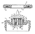
Die Erfindung und vorteilhafte Einzelheiten werden nachfolgend anhand eines Ausführungsbeispiels unter Bezug auf die Zeichnung näher erläutert. Die einzige Figur zeigt in schematischer Darstellung das Schnittbild eines erfindungsgemäßen Kombinationssensors.The invention and advantageous details are explained below using an exemplary embodiment with reference to the drawing. The single figure shows a schematic representation of the sectional view of a combination sensor according to the invention.
Die Zeichnung läßt ein ringförmiges Gehäuse 4 aus Kunststoff erkennen mit einem mittigen Durchbruch 15, in den ein Metallkörper 5 vorzugsweise aus Silber (Ag) paßgenau eingesetzt ist, der in der Darstellung oberseitig, d. h. die (spätere) Meßfläche 10 überdeckend mit einer SilberSilberchlorid-Referenzelektrode 3 versehen ist. Der Durchbruch 15 wird durch eine zylindrische Wandung 21 begrenzt, die umlaufend geringfügig über die Oberfläche der Referenzelektrode 3 übersteht, so daß zusätzlich, bedingt durch eine randseitige Zurücksetzung der Referenzelektrode 3, ein Elektrolytreservoir 22 gebildet ist. Der Metallkörper 5 weist, die Referenzelektrode 3 ebenfalls durchsetzend, eine zentrale Bohrung 12 auf, in die in konzentrischer Anordnung eine pH-Meßelektrode 1 eingepaßt ist, welche bei der bevorzugten Ausführungsform eine Iridium/Iridiumoxid(Ir/IrOx-)-Elektrode ist, die beispielsweise einen Durchmesser von 2 mm aufweist. Diese Elektrode 1 ist gegen die Referenzelektrode 3 sowie gegen den Metallkörper 5 durch eine Kunststoff-Gießharzschicht 2 isoliert. Wie aus der DE-A1-32 32 515 bekannt, kann die Ir/IrOx-Elektrode 1 aus einem einheitlichen zylinderförmigen Iridiumstück hergestellt sein, das oberflächenseitig, also auf der einer Membran 13 zugekehrten und in einen Elektrolyten 8 eintauchenden Oberfläche oxidiert ist. Iridium ist jedoch ein vergleichsweise sehr teures Metall. Aus diesem Grund wird es schon aus Preisgründen in der Regel vorteilhaft sein, den Körper der Ir/IrOx-Elektrode 1 stirnseitig, d. h. auf der in den Elektrolyten 8 eintauchenden Oberfläche, mit einem Iridiumplättchen 11 zu versehen, das mit dem übrigen Elektrodenkörper la, der beispielsweise aus Silber oder Kupfer bestehen kann, elektrisch und thermisch gut leitend verbunden ist. Die in den Elektrolyten 8 eintauchende Oberfläche des Iridiumplättchens 11 ist in diesem Fall elektrochemisch oder thermochemisch oxidiert, wobei das Oxid auch in hydratisierter Form als Iridiumoxidhydrat vorliegen kann. Die Referenzelektrode 3 ist entweder durch eine zumindest teilweise chlorierte Oberfläche des aus Silber bestehenden Metallkörpers 5 gebildet oder als ringförmiges Plättchen aus Silber/Silberchlorid-Sintermetall auf den Metallkörper 5 aufplattiert. Der Metallkörper 5 ist im Bereich seiner umlaufenden Mantelfläche mit einer ringförmig umlaufenden breiten Nut versehen, in die eine Heizwicklung 7 eingesetzt ist. Die Heizleistungszufuhr zum Metallkörper 5 wird über wenigstens einen in eine exzentrische Bohrung 6 eingesetzten Temperaturfühler, beispielsweise einen Thermistor 23, geregelt. In an sich bekannter Weise kann ein weiterer (nicht gezeigter) Temperaturfühler, wiederum beispielsweise ein Thermistor, in den Metallkörper 5 eingesetzt sein, der ein (nicht gezeigtes) Schalterelement zur unmittelbaren Unterbrechung der Heizleistungszufuhr zur Heizwicklung 7 steuert, wenn die Temperatur im Metallkörper einen vorgebbaren Schwellenwert von beispielsweise 42°C überschreitet.The drawing shows an annular housing 4 made of plastic with a
Die so weit beschriebene und an sich beispielsweise aus der DE-A1-32 32 515 bekannte pCO₂-Meßvorrichtung mit pH-Meßelektrode ist erfindungsgemäß mit einer sO₂-Meßvorrichtung kombiniert, die bei der dargestellten Ausführungsform einerseits aus zwei photoelektrischen Senderelementen in Form zweier lichtemittierender Dioden 24 und 25 und andererseits aus einem photoelektrischen Empfängerelement 26 besteht, das vorzugsweise ein Silicium-Photoelement (Si-Photoelement) sein wird. Die beiden lichtemittierenden Diodenelemente 24 und 25 sind in eine muldenartige Aussparung 27 in der Schicht aus Ag/AgCl der Referenzelektrode 3 bzw. des Metallkörpers 5 eingesetzt, die mit einer lichtdurchlässigen Vergußmasse 28 feuchtigkeits- und luftdicht ausgegossen ist, die oberflächenseitig, d.h. auf der der Membran 13 zugekehrten Meßflächenseite, plan verschliffen und poliert ist. Die lichtdurchlässige Vergußmasse 28 kann gleichzeitig als (zusätzliche) Passivierungsschicht für die lichtemittierenden Dioden 24 und 25 dienen. Die Lichtaustrittsseiten der Dioden 24 und 25 sind auf die nach der weiter unten beschriebenen Vervollständigung des Sensors zwischen der Meßfläche und der Membran vorhandenen Schicht des Elektrolyten 8 so ausgerichtet, daß sich ihre Strahlen nicht gegenseitig stören. Die Signalzuführung zu den Dioden 24 und 25 erfolgt über Zuleitungsdrähte 29, welche eine Bohrung 30 im Metallkörper 5 durchsetzen. Die Bohrung 30 kann ebenfalls mit einem geeigneten Gießharz ausgefüllt sein.The so far described and known per se for example from DE-A1-32 32 515 pCO₂ measuring device with pH measuring electrode is combined according to the invention with an sO₂ measuring device which, in the embodiment shown, consists of two photoelectric transmitter elements in the form of two light-
Das photoelektrische Empfängerelement 26 ist in ähnlicher Weise wie die Dioden 24 und 25 in eine muldenartige Aussparung 31 mittels einer ebenfalls lichtdurchlässigen Vergußmasse 32 in Ausrichtung auf die Meßfläche bzw. die Membran 13 und die (spätere) Elektrolytschicht 8 eingesetzt. Die Signalabnahme erfolgt über Leitungsdrähte 33, welche eine weitere, im Endzustand des Sensors ebenfalls mit ausgehärtetem Gießharz gefüllte Bohrung 34 im Metallkörper 5 durchsetzen.The
Die beiden lichtemittierenden Dioden 24 und 25 geben bei entsprechender Erregung Licht unterschiedlicher Wellenlänge ab. Eine dieser Wellenlängen wird in Anpassung auf den Extinktionskoeffizienten von Hämoglobin bzw. Oxyhämoglobin oder in anderen Worten isosbestisch für Hämoglobin bzw. Oxyhämoglobin im Ultrarotbereich und insbesondere zu λ = 805 nm gewählt, während die Wellenlänge für die andere Diode im Rotbereich beispielsweise bei etwa λ = 650 nm gewählt wird. Die Ansteuerung der beiden lichtemittierenden Dioden 24 und 25 bzw. die Signalauswertung erfolgt zweckmäßigerweise, wie bereits oben erwähnt, nach dem Prinzip der Pulsoxymetrie.The two light-
Um den Sensor für einen Meßvorgang vorzubereiten wird, wie die Zeichnung erkennen läßt, ein kleiner Tropfen des Elektrolyten 8 auf die durchgehende Oberfläche 14 (Meßfläche) der Referenzelektrode 3, der oberflächenseitig polierten lichtdurchlässigen Vergußmassen 28 und 32 sowie der Ir/IrOx-Elektrode 1 aufgebracht. Sodann wird der Kombinationssensor mit einer vorgefertigten einmal zu benutzenden Schnappring-Membranvorrichtung 9 bespannt. Der leicht gewölbt gefertigte Schnappring 9 weist eine nach innen vorspringende umlaufende Rastkante 19 auf. Wird der Schnappring 9 auf das Gehäuse 4 aufgedrückt, so rastet die Rastkante 19 hinter einem vorspringenden Rand 20 am Gehäuse ein und die für CO₂ und Licht durchlässige Membran 13 wird genau zentriert über die Oberfläche 14 gespannt unter Zwischenschaltung einer dünnen Schicht des Elektrolyten 8. Der die Membran 13 vorzentriert und gespannt haltende Schnappring 9 ist bekannt und beispielsweise in der DE-A1-30 40 544 beschrieben.In order to prepare the sensor for a measuring process, as the drawing shows, a small drop of the electrolyte 8 is applied to the continuous surface 14 (measuring surface) of the reference electrode 3, the translucent casting compounds 28 and 32 polished on the surface and the Ir / IrOx electrode 1 . The combination sensor is then covered with a prefabricated snap ring membrane device 9 to be used. The slightly domed snap ring 9 has an inwardly projecting circumferential locking edge 19. If the snap ring 9 is pressed onto the housing 4, the latching edge 19 snaps behind a projecting
Die lichtemittierenden Dioden 24, 25, bzw. die photoelektrischen Empfängerelemente 32, können an anderer Stelle, beispielsweise im Meßgerät selbst, angeordnet sein und die Lichtzu- bzw. -abführung kann über dünne Glasfasern zur bzw. von der Meßfläche 14 erfolgen.The light-emitting
Claims (7)
- Combined sensor, with an electric heating device (6, 7) thermostated at a temperature of T ≦ 42°C, for the transcutaneous measurement of oxygen (O₂) and carbon dioxide (CO₂) in the blood, and with a common sensor housing (4) in which are incorporated an electrometric measuring device for the partial pressure of CO₂ (pCO₂) with an iridium/iridium oxide measuring electrode (11) which is covered by an electrolyte (8) which is separated from the measuring site on the skin by a membrane (13) which is permeable to CO₂ and light, and a measuring device (24, 25, 26) for the measurement of the blood oxygen saturation (sO₂) by spectrometry.
- Combined sensor according to Claim 1, characterised in that the measuring device for spectrometric measurement has two light-emitting diodes (24, 25) which are inserted in the measuring surface (14) of the sensor and emit light of different wavelengths, and has at least one photoelectric receiver (26) which is likewise inserted in the sensor measuring surface (14).
- Combined sensor according to Claim 1, characterised in that the measuring device for the spectrometric sO₂ measurement has two light-emitting diodes which [lacuna] light of different wavelengths, and has at least one photoelectric receiving unit, and in that the light-emitting diodes and the receiving unit are connected to the sensor by light guides terminating on the sensor measuring surface (14).
- Combined sensor according to Claim 3, characterised in that the light-emitting diodes (24, 25) and the photoelectric receiving units (32) [sic] are embedded in the sensor measuring surface (14) by a light-transmitting casting composition (28, 32).
- Combined sensor according to Claim 3, characterised in that one wavelength is chosen to be in the infrared region and the other wavelength is chosen to be in the red region of the electromagnetic spectrum.
- Combined sensor according to Claim 5, characterised in that one wavelength is chosen to be isosbestic for haemoglobin and oxyhaemoglobin, and is preferably λ = 805 nm, and the other wavelength is chosen to be about λ = 650 nm.
- Combined sensor according to either of Claims 5 or 6, characterised in that the light-emitting diodes (24, 25) can be excited intermittently by the monitoring and evaluating apparatus at a rate equal to the pulse rate, and in that the signal is evaluated in harmony with the pulse phases of the arterial filling of the area measured.
Priority Applications (5)
| Application Number | Priority Date | Filing Date | Title |
|---|---|---|---|
| EP86115941A EP0267978B1 (en) | 1986-11-17 | 1986-11-17 | Combination sensor for the transcutaneous detection of oxygen and carbon dioxide in blood |
| DE8686115941T DE3681175D1 (en) | 1986-11-17 | 1986-11-17 | COMBINATION SENSOR FOR TRANSCUTANEAL DETECTION OF OXYGEN AND CARBON DIOXIDE IN THE BLOOD. |
| JP62290429A JPS63130045A (en) | 1986-11-17 | 1987-11-17 | Bonding sensor |
| US07/121,713 US4840179A (en) | 1986-11-17 | 1987-11-17 | Combined sensor for the transcutaneous measurement of oxygen and carbon dioxide in the blood |
| US07/340,339 US4930506A (en) | 1986-11-17 | 1989-04-19 | Combined sensor for the transcutaneous measurement of oxygen and carbon dioxide in the blood |
Applications Claiming Priority (1)
| Application Number | Priority Date | Filing Date | Title |
|---|---|---|---|
| EP86115941A EP0267978B1 (en) | 1986-11-17 | 1986-11-17 | Combination sensor for the transcutaneous detection of oxygen and carbon dioxide in blood |
Publications (2)
| Publication Number | Publication Date |
|---|---|
| EP0267978A1 EP0267978A1 (en) | 1988-05-25 |
| EP0267978B1 true EP0267978B1 (en) | 1991-08-28 |
Family
ID=8195604
Family Applications (1)
| Application Number | Title | Priority Date | Filing Date |
|---|---|---|---|
| EP86115941A Expired - Lifetime EP0267978B1 (en) | 1986-11-17 | 1986-11-17 | Combination sensor for the transcutaneous detection of oxygen and carbon dioxide in blood |
Country Status (4)
| Country | Link |
|---|---|
| US (2) | US4840179A (en) |
| EP (1) | EP0267978B1 (en) |
| JP (1) | JPS63130045A (en) |
| DE (1) | DE3681175D1 (en) |
Families Citing this family (45)
| Publication number | Priority date | Publication date | Assignee | Title |
|---|---|---|---|---|
| DE3810008C1 (en) * | 1988-03-24 | 1989-10-26 | Johannes Dr. 8000 Muenchen De Buschmann | |
| GB8819086D0 (en) * | 1988-08-11 | 1988-09-14 | Univ Wales Medicine | "in-vivo"oxygen tension measurement |
| JP2766317B2 (en) * | 1989-06-22 | 1998-06-18 | コーリン電子株式会社 | Pulse oximeter |
| US5080098A (en) * | 1989-12-18 | 1992-01-14 | Sentinel Monitoring, Inc. | Non-invasive sensor |
| US5222495A (en) * | 1990-02-02 | 1993-06-29 | Angiomedics Ii, Inc. | Non-invasive blood analysis by near infrared absorption measurements using two closely spaced wavelengths |
| US5222496A (en) * | 1990-02-02 | 1993-06-29 | Angiomedics Ii, Inc. | Infrared glucose sensor |
| US5246004A (en) * | 1990-02-02 | 1993-09-21 | Angiomedics Ii, Inc. | Infrared cholesterol sensor |
| US5104623A (en) * | 1990-04-03 | 1992-04-14 | Minnesota Mining And Manufacturing Company | Apparatus and assembly for use in optically sensing a compositional blood parameter |
| US5124130A (en) * | 1990-05-22 | 1992-06-23 | Optex Biomedical, Inc. | Optical probe |
| US5204265A (en) * | 1990-10-15 | 1993-04-20 | Puritan-Bennett Corporation | Method of stabilizing a carbon dioxide sensor |
| EP0502270B1 (en) * | 1991-03-07 | 1997-01-02 | Hamamatsu Photonics K.K. | Tissue oxygen measuring system |
| US5267563A (en) * | 1991-06-28 | 1993-12-07 | Nellcor Incorporated | Oximeter sensor with perfusion enhancing |
| US5273041A (en) * | 1992-04-30 | 1993-12-28 | General Electric Company | Fiber optic photoplethysmograph for a magnetic resonance imaging system |
| US5792050A (en) * | 1992-07-06 | 1998-08-11 | Alam; Mary K. | Near-infrared noninvasive spectroscopic determination of pH |
| US5355880A (en) * | 1992-07-06 | 1994-10-18 | Sandia Corporation | Reliable noninvasive measurement of blood gases |
| WO1994012096A1 (en) * | 1992-12-01 | 1994-06-09 | Somanetics Corporation | Patient sensor for optical cerebral oximeters |
| JPH09501074A (en) * | 1993-05-20 | 1997-02-04 | ソマネテイツクス コーポレイシヨン | Improved electro-optical sensor for spectrophotometric medical devices |
| WO1994027493A1 (en) * | 1993-05-28 | 1994-12-08 | Somanetics Corporation | Method and apparatus for spectrophotometric cerebral oximetry |
| US5645059A (en) * | 1993-12-17 | 1997-07-08 | Nellcor Incorporated | Medical sensor with modulated encoding scheme |
| US5560355A (en) * | 1993-12-17 | 1996-10-01 | Nellcor Puritan Bennett Incorporated | Medical sensor with amplitude independent output |
| US5697367A (en) * | 1994-10-14 | 1997-12-16 | Somanetics Corporation | Specially grounded sensor for clinical spectrophotometric procedures |
| JPH09122128A (en) * | 1995-10-31 | 1997-05-13 | Kdk Corp | Measurement condition reproducing tool, measurement condition reproducing method and biological information utilizing the same |
| CA2303803A1 (en) * | 1997-06-17 | 1998-12-23 | Respironics, Inc. | Fetal oximetry system and sensor |
| US5967982A (en) * | 1997-12-09 | 1999-10-19 | The Cleveland Clinic Foundation | Non-invasive spine and bone registration for frameless stereotaxy |
| US5916154A (en) * | 1998-04-22 | 1999-06-29 | Nellcor Puritan Bennett | Method of enhancing performance in pulse oximetry via electrical stimulation |
| CA2290083A1 (en) | 1999-11-19 | 2001-05-19 | Linde Medical Sensors Ag. | Device for the combined measurement of the arterial oxygen saturation and the transcutaneous co2 partial pressure of an ear lobe |
| CA2466105C (en) | 2000-11-23 | 2012-06-19 | Sentec Ag | Sensor and method for measuring physiological parameters |
| US6760610B2 (en) | 2000-11-23 | 2004-07-06 | Sentec Ag | Sensor and method for measurement of physiological parameters |
| AU2002312565A1 (en) * | 2001-06-19 | 2003-01-02 | University Of Southern California | Therapeutic decisions systems and method using stochastic techniques |
| SE523698C2 (en) * | 2002-04-26 | 2004-05-11 | Gert Nilsson | Method and apparatus for non-invasive measurement of transcutaneous oxygen uptake |
| DK1535055T3 (en) | 2002-08-06 | 2009-03-23 | Sentec Ag | Device and method for preparing an electrochemical sensor |
| US7651989B2 (en) * | 2003-08-29 | 2010-01-26 | Kimberly-Clark Worldwide, Inc. | Single phase color change agents |
| FR2863175A1 (en) * | 2003-12-03 | 2005-06-10 | Ela Medical Sa | ACTIVE IMPLANTABLE MEDICAL DEVICE WITH HOLTER RECORDING FUNCTIONS |
| KR20050055202A (en) * | 2003-12-05 | 2005-06-13 | 한국전자통신연구원 | Micro reference electrode of implantable continuous biosensor using iridium oxide, manufacturing method thereof, and implantable continuous biosensor |
| US7611621B2 (en) * | 2005-06-13 | 2009-11-03 | Nova Biomedical Corporation | Disposable oxygen sensor and method for correcting oxygen effect on oxidase-based analytical devices |
| US20060287215A1 (en) * | 2005-06-17 | 2006-12-21 | Mcdonald J G | Color-changing composition comprising a thermochromic ingredient |
| US7648624B2 (en) * | 2005-07-26 | 2010-01-19 | Nova Biomedical Corporation | Oxygen sensor |
| US8067350B2 (en) | 2005-12-15 | 2011-11-29 | Kimberly-Clark Worldwide, Inc. | Color changing cleansing composition |
| US20070142263A1 (en) * | 2005-12-15 | 2007-06-21 | Stahl Katherine D | Color changing cleansing composition |
| US20080236297A1 (en) * | 2007-01-23 | 2008-10-02 | Geoff Van Fleet | Acoustically compatible insert for an ultrasonic probe |
| ITMI20070110A1 (en) * | 2007-01-25 | 2008-07-26 | Elio Scarano | SENSOR AND APPLIANCE FOR THE ANALYSIS OF GAS PRESENT IN THE BLOOD |
| WO2008132205A1 (en) * | 2007-04-27 | 2008-11-06 | Sentec Ag | Device and method for transcutaneous determination of blood gases |
| US11457842B2 (en) * | 2008-01-15 | 2022-10-04 | Patient Shield Concepts, Llc | Method and apparatus for determining a deterioration of respiratory function |
| EP2151680A1 (en) * | 2008-08-05 | 2010-02-10 | F. Hoffmann-Roche AG | Assembly method for manufacturing an analysis system |
| JP5172002B1 (en) | 2011-09-08 | 2013-03-27 | 和気 清弘 | Antimicrobial agent in bag |
Family Cites Families (12)
| Publication number | Priority date | Publication date | Assignee | Title |
|---|---|---|---|---|
| US3628525A (en) * | 1969-06-19 | 1971-12-21 | American Optical Corp | Blood oxygenation and pulse rate monitoring apparatus |
| CH530006A (en) | 1970-10-01 | 1972-10-31 | Hoffmann La Roche | Electrode arrangement |
| US3769974A (en) * | 1971-06-29 | 1973-11-06 | Martin Marietta Corp | Blood pulse measuring employing reflected red light |
| DE2305049C2 (en) | 1973-02-02 | 1984-10-25 | L. Eschweiler & Co, 2300 Kiel | Device for measuring the pH value of blood |
| GB2033575B (en) * | 1978-05-24 | 1983-03-02 | Rolfe P | Investigating substances in a patient's bloodstream |
| US4259963A (en) * | 1979-07-03 | 1981-04-07 | Albert Huch | Multi-purpose transducer for transcutaneous blood measurements |
| DE2927814C2 (en) * | 1979-07-10 | 1982-08-05 | Hellige Gmbh, 7800 Freiburg | Method and device for the transcutaneous photometric determination of the concentration of constituents in the blood |
| DE3040544C2 (en) | 1980-07-04 | 1985-08-08 | Hellige Gmbh, 7800 Freiburg | Clamping ring for tensioning and fixing a measuring surface membrane on a measuring transducer |
| DE3232515A1 (en) | 1982-09-01 | 1984-03-01 | Hellige Gmbh, 7800 Freiburg | ELECTROCHEMICAL SENSOR FOR TRANSCUTANE MEASUREMENT OF THE CARBON DIOXIDE PARTIAL PRESSURE OF A LIVING BEING |
| US4621643A (en) * | 1982-09-02 | 1986-11-11 | Nellcor Incorporated | Calibrated optical oximeter probe |
| DE3382674T2 (en) * | 1982-09-02 | 1993-07-08 | Nellcor Inc | OXYGEN MEASURING DEVICE WITH OXYGEN MEASURING PROBE. |
| US4557900A (en) * | 1982-09-28 | 1985-12-10 | Cardiovascular Devices, Inc. | Optical sensor with beads |
-
1986
- 1986-11-17 EP EP86115941A patent/EP0267978B1/en not_active Expired - Lifetime
- 1986-11-17 DE DE8686115941T patent/DE3681175D1/en not_active Expired - Fee Related
-
1987
- 1987-11-17 JP JP62290429A patent/JPS63130045A/en active Granted
- 1987-11-17 US US07/121,713 patent/US4840179A/en not_active Expired - Fee Related
-
1989
- 1989-04-19 US US07/340,339 patent/US4930506A/en not_active Expired - Fee Related
Also Published As
| Publication number | Publication date |
|---|---|
| DE3681175D1 (en) | 1991-10-02 |
| US4930506A (en) | 1990-06-05 |
| EP0267978A1 (en) | 1988-05-25 |
| JPH0352B2 (en) | 1991-01-07 |
| JPS63130045A (en) | 1988-06-02 |
| US4840179A (en) | 1989-06-20 |
Similar Documents
| Publication | Publication Date | Title |
|---|---|---|
| EP0267978B1 (en) | Combination sensor for the transcutaneous detection of oxygen and carbon dioxide in blood | |
| EP2096984B1 (en) | Medical measuring device | |
| AT392847B (en) | SENSOR ELECTRODE ARRANGEMENT | |
| EP2403398B1 (en) | Diagnostic measuring device | |
| EP2203114B1 (en) | Medical measuring device for bioelectrical impedance measurement | |
| EP1931239B1 (en) | Medical measuring device | |
| DE60301868T2 (en) | Blood glucose meter | |
| EP2144555B1 (en) | Device and method for transcutaneous determination of blood gases | |
| DE2758413C3 (en) | Device for the transcutaneous measurement of the arterial oxygen partial pressure | |
| DE102005057757A1 (en) | Integrated-type physiological signal evaluation apparatus for measuring cardiovascular parameters, has detection interface modules having two electrodes for obtaining electrocardiogram signal of subject | |
| DE19832361A1 (en) | Body function monitor measures bodily conditions, determines environmental stresses, pauses and computes probabilities, before pronouncing on criticality with high confidence level | |
| DE102005038147A1 (en) | Combination sensor for the acquisition of physiological measurements on the skin of a patient | |
| DE60314388T2 (en) | Device for measuring blood sugar level | |
| EP1335666B1 (en) | Sensor and method for measuring physiological parameters | |
| DE2823769C2 (en) | Measuring head with thermal stabilization | |
| DE2930663A1 (en) | Monitor for diagnostic analysis - has membrane with electrodes spaced about it for blood gas partial pressure and blood content measurement | |
| EP0102033B1 (en) | Electrochemical sensor for the transcutaneous measuring of the carbon dioxide partial pressure of a living being | |
| DE10352188A1 (en) | Sensor arrangement for determining the vital condition of a person to be monitored medically | |
| DE102006051561A1 (en) | Physiological measuring value e.g. oxygen concentration, displaying unit, has sensor unit for detecting and transmitting physiological measuring value e.g. oxygen concentration, and separated from device | |
| DE4011065A1 (en) | DEVICE FOR BREATHING MONITORING | |
| DD292718A5 (en) | SENSOR FOR MEASURING THE ACTIVITY OF IONES, METHOD FOR THE PRODUCTION THEREOF, AND SENSORS AND APPROPRIATE ARRANGEMENT | |
| DE102013222123A1 (en) | Mobile monitoring device | |
| EP0793975A2 (en) | Device for controlling a pacemaker based on the blood oxygen saturation | |
| Sakuntala et al. | Remote Health Monitoring System Using PIC Microcontroller | |
| DE19613225C1 (en) | Device for the simultaneous epi-tissue measurement of the intra-tissue oxygen partial pressure and the oxygen conductivity |
Legal Events
| Date | Code | Title | Description |
|---|---|---|---|
| PUAI | Public reference made under article 153(3) epc to a published international application that has entered the european phase |
Free format text: ORIGINAL CODE: 0009012 |
|
| 17P | Request for examination filed |
Effective date: 19870916 |
|
| AK | Designated contracting states |
Kind code of ref document: A1 Designated state(s): CH DE FR GB LI |
|
| 17Q | First examination report despatched |
Effective date: 19880902 |
|
| GRAA | (expected) grant |
Free format text: ORIGINAL CODE: 0009210 |
|
| RAP1 | Party data changed (applicant data changed or rights of an application transferred) |
Owner name: PPG HELLIGE GMBH |
|
| AK | Designated contracting states |
Kind code of ref document: B1 Designated state(s): CH DE FR GB LI |
|
| REF | Corresponds to: |
Ref document number: 3681175 Country of ref document: DE Date of ref document: 19911002 |
|
| GBT | Gb: translation of ep patent filed (gb section 77(6)(a)/1977) | ||
| EN | Fr: translation not filed | ||
| PG25 | Lapsed in a contracting state [announced via postgrant information from national office to epo] |
Ref country code: FR Effective date: 19920117 |
|
| PLBE | No opposition filed within time limit |
Free format text: ORIGINAL CODE: 0009261 |
|
| STAA | Information on the status of an ep patent application or granted ep patent |
Free format text: STATUS: NO OPPOSITION FILED WITHIN TIME LIMIT |
|
| 26N | No opposition filed | ||
| REG | Reference to a national code |
Ref country code: FR Ref legal event code: ST |
|
| PGFP | Annual fee paid to national office [announced via postgrant information from national office to epo] |
Ref country code: GB Payment date: 19960910 Year of fee payment: 11 |
|
| PGFP | Annual fee paid to national office [announced via postgrant information from national office to epo] |
Ref country code: DE Payment date: 19970822 Year of fee payment: 12 |
|
| PG25 | Lapsed in a contracting state [announced via postgrant information from national office to epo] |
Ref country code: GB Free format text: LAPSE BECAUSE OF NON-PAYMENT OF DUE FEES Effective date: 19971117 |
|
| GBPC | Gb: european patent ceased through non-payment of renewal fee |
Effective date: 19971117 |
|
| PGFP | Annual fee paid to national office [announced via postgrant information from national office to epo] |
Ref country code: CH Payment date: 19981030 Year of fee payment: 13 |
|
| PG25 | Lapsed in a contracting state [announced via postgrant information from national office to epo] |
Ref country code: LI Free format text: LAPSE BECAUSE OF NON-PAYMENT OF DUE FEES Effective date: 19981130 Ref country code: CH Free format text: LAPSE BECAUSE OF NON-PAYMENT OF DUE FEES Effective date: 19981130 |
|
| REG | Reference to a national code |
Ref country code: CH Ref legal event code: PL |
|
| PG25 | Lapsed in a contracting state [announced via postgrant information from national office to epo] |
Ref country code: DE Free format text: LAPSE BECAUSE OF NON-PAYMENT OF DUE FEES Effective date: 19990901 |