EP0262273A1 - Electric water heating element - Google Patents
Electric water heating element Download PDFInfo
- Publication number
- EP0262273A1 EP0262273A1 EP19860310042 EP86310042A EP0262273A1 EP 0262273 A1 EP0262273 A1 EP 0262273A1 EP 19860310042 EP19860310042 EP 19860310042 EP 86310042 A EP86310042 A EP 86310042A EP 0262273 A1 EP0262273 A1 EP 0262273A1
- Authority
- EP
- European Patent Office
- Prior art keywords
- coils
- heating element
- water
- hot water
- heater
- Prior art date
- Legal status (The legal status is an assumption and is not a legal conclusion. Google has not performed a legal analysis and makes no representation as to the accuracy of the status listed.)
- Withdrawn
Links
Images


Classifications
-
- A—HUMAN NECESSITIES
- A47—FURNITURE; DOMESTIC ARTICLES OR APPLIANCES; COFFEE MILLS; SPICE MILLS; SUCTION CLEANERS IN GENERAL
- A47J—KITCHEN EQUIPMENT; COFFEE MILLS; SPICE MILLS; APPARATUS FOR MAKING BEVERAGES
- A47J31/00—Apparatus for making beverages
- A47J31/04—Coffee-making apparatus with rising pipes
- A47J31/057—Coffee-making apparatus with rising pipes with water container separated from beverage container, the hot water passing the filter only once i.e. classical type of drip coffee makers
- A47J31/0573—Coffee-making apparatus with rising pipes with water container separated from beverage container, the hot water passing the filter only once i.e. classical type of drip coffee makers with flow through heaters
-
- A—HUMAN NECESSITIES
- A47—FURNITURE; DOMESTIC ARTICLES OR APPLIANCES; COFFEE MILLS; SPICE MILLS; SUCTION CLEANERS IN GENERAL
- A47J—KITCHEN EQUIPMENT; COFFEE MILLS; SPICE MILLS; APPARATUS FOR MAKING BEVERAGES
- A47J31/00—Apparatus for making beverages
- A47J31/44—Parts or details or accessories of beverage-making apparatus
- A47J31/54—Water boiling vessels in beverage making machines
-
- H—ELECTRICITY
- H05—ELECTRIC TECHNIQUES NOT OTHERWISE PROVIDED FOR
- H05B—ELECTRIC HEATING; ELECTRIC LIGHT SOURCES NOT OTHERWISE PROVIDED FOR; CIRCUIT ARRANGEMENTS FOR ELECTRIC LIGHT SOURCES, IN GENERAL
- H05B3/00—Ohmic-resistance heating
- H05B3/78—Heating arrangements specially adapted for immersion heating
- H05B3/82—Fixedly-mounted immersion heaters
Definitions
- This invention relates to electric heating elements for liquids.
- Electric heating elements employed in, for example kettles, water boilers or coffee making apparatus have to be cleaned at regular intervals to remove scale which builds up on the surface of the element especially in "hard water” areas and which restricts the efficiency of the element.
- the general object of this invention is to provide an element on which scale does not build up on the element as fast as hitherto.
- an apparatus for heating and dispensing liquid has an electric heating element formed as a spiral with at least two coils for heating liquid to boiling point, the heating element supported by and positioned in the apparatus whereby the area underneath the coils is substantially free of obstruction so that scale can crack off the coils and fall freely such a distance as to prevent build-up of scale around the lowermost portions of the coils, and means for dispensing the heated liquid from the apparatus.
- the lowermost portions of the coils are suitably positioned a distance from any obstruction corresponding to at least the radius of the coils (and more preferably at least three times the radius of the coils).
- spiral shape will employ a longer length of strip which will be of somewhat smaller cross sectional area (e.g. between 40 and 60 mm2, and suitably 50 mm2) than that of a conventional heating element.
- the coils suitably have a linear expansion coefficient between 17 and 22 x 10 ⁇ 6K ⁇ 1, and more preferably between 18.5 and 20.5 x 10 ⁇ 6K ⁇ 1.
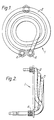
- the element 1 comprises a strip 2 formed into a spiral having about three coils.
- the two free ends 4 and 6 are brazed to standard bushes for connection to standard electric connections of a water heating boiler or the like.
- the coils are positioned one slightly above the other although they could be formed into a flat configuration.
- the strip should be made of material having a relatively high coefficient of expansion, preferably at least that of copper.
- the strip may be made of copper with an electro-tin finish or of stainless steel.
- the element 1 may be mounted with the major axis of the coils either vertically or horizontally in the heater and as can be seen the coils of the element are free to expand and contract in all directions.
- a sensor In use, a sensor would normally be provided closely adjacent the outermost coil so that electric current to the circuit is broken unless the coil is fully covered by water or other liquid to be heated.
- the outer coil may have a radius of 57 mm and the inner a radius of about 271 ⁇ 2 mm.
- FIG. 3 to 5 An application of the heating element 1 is shown in Figures 3 to 5 which illustrates a hot water dispenser 18 having a tank 20 forming a hot water container of typically about 5.7 litres capacity with a draw-off tap 22 located about half way up so that an approximate equal volume of the tank is above and below the tap.
- a heater 24 having a housing 25 incorporating the heating element 1 horizontally (see Figure 4), forms the base of the tank, and just above the element 1 a thermostat phial 26 is mounted in the tank wall and is connected to a controller 28.
- a conduit 30 extends through the base of the heater 24 to a shut-off valve 32 operated by solenoid 34.
- the heating element 1 is connected by lines 38 to controller 28 via a thermal safety cut-out 40.
- a further conduit 42 connects valve 32 to a cold water container 44 having a typical capacity of 2.8 litres.
- Conduits 42 and 30 form a connecting means between the cold water container 44 and the hot water container defined by tank 20.
- FIG. 6 to 8 illustrates a coffee making apparatus 50 comprising a casing or body 52 having an internal cold water tank or reservoir 54 positioned at its top and having an inlet 56 through the top of the casing 52 to receive cold water from a flask, which inlet may be closed by cover 58.
- the cold water tank 54 is connected to an inlet 60 of a heater 59 by means of a flexible pipe or conduit 62.
- the heater 59 comprises a rear housing portion 76 and a front housing portion 78, the front housing portion 78 being secured to the rear housing portion 76 by four wing nuts 80.
- the inlet 60 has an adjustable water flow controller 82 in order to control the rate of flow of cold water into the heater 59. After water is heated in the heater 59, the heated water flows from the heater through an outlet 64 to a flexible pipe or conduit 66 which passes up adjacent the cold water tank 54 and connects with a spray head 68 positioned above the coffee infused basket 70. Switches 77 for the apparatus are mounted at the front of the apparatus.
- a thermal cut-out is provided for the apparatus 50, whereby in the event there is no water in the heater 59, the thermal cut-out would trip thus saving the element 1 from destruction.
- the thermal cut-out after tripping is mechanically reset using a mechanical reset arm 74.
- Access to one face of the heater 59 is by means of an access opening 84 at the rear of the apparatus casing 52 and the access opening is covered by a cover plate 86 which is retained in the casing at its top by means of a lip portion 88 and at the bottom by means of a bracket 90 which engages over a retaining member 92. Removal of the cover 86 is by lifting the cover so that bracket 90 disengages with member 92 and by lifting the bottom of the cover 86 away from casing 52 and allowing top of the cover to drop out of retention by lip 88.
- Access to the other face of the heater 59 is by means of an access opening (not shown) in the panel 94 positioned behind the coffee jug.
Abstract
An apparatus for heating and dispensing liquid having an electric heating element (1) formed as a spiral whereby continual expansion and contraction thereof causes scale thereon to "crack off", the element being supported by and positioned in the apparatus such that the area underneath the element is substantially free of obstruction in order that scale can crack off and fall freely a distance as to prevent build-up of scale around the element.
Description
- This invention relates to electric heating elements for liquids.
- Electric heating elements employed in, for example kettles, water boilers or coffee making apparatus have to be cleaned at regular intervals to remove scale which builds up on the surface of the element especially in "hard water" areas and which restricts the efficiency of the element.
- The general object of this invention is to provide an element on which scale does not build up on the element as fast as hitherto.
- In accordance with the present invention, an apparatus for heating and dispensing liquid has an electric heating element formed as a spiral with at least two coils for heating liquid to boiling point, the heating element supported by and positioned in the apparatus whereby the area underneath the coils is substantially free of obstruction so that scale can crack off the coils and fall freely such a distance as to prevent build-up of scale around the lowermost portions of the coils, and means for dispensing the heated liquid from the apparatus.
- It has been found that scale tends to break away from a water heating element at the point of maximum curvature and thus by forming the element in the form of a spiral, as compared with the conventional modified "mushroom" shape, the area of the strip which is curved is much higher than has been used hitherto. When carrying current the spiral strip will expand in all directions, and when not carrying current the spiral strip will contract. This continual expansion and contraction (or in the case of a spirally wound element, this winding and un-winding) will tend to 'crack off' scale from the curved surface.
- The lowermost portions of the coils are suitably positioned a distance from any obstruction corresponding to at least the radius of the coils (and more preferably at least three times the radius of the coils).
- Normally the spiral shape will employ a longer length of strip which will be of somewhat smaller cross sectional area (e.g. between 40 and 60 mm², and suitably 50 mm²) than that of a conventional heating element.
- The coils suitably have a linear expansion coefficient between 17 and 22 x 10⁻⁶K⁻¹, and more preferably between 18.5 and 20.5 x 10⁻⁶K⁻¹.
- The invention will now be further described by way of example with reference to the accompanying drawings in which:-
- Figure 1 is a plan view of an electric heating element for liquids in accordance with the invention,
- Figure 2 is an end elevation of the element shown in Figure 1,
- Figure 3 is a schematic side elevation of a hot water dispenser incorporating a heating element in accordance with the invention,
- Figure 4 is an enlarged plan view of the heater portion of the dispenser shown in Figure 3,
- Figure 5 is a side view of the heater portion of Figure 4,
- Figure 6 is a schematic side elevation of a coffee making apparatus incorporating a heating element in accordance with the invention,
- Figure 7 is an enlarged front view of the heater portion of the apparatus shown in Figure 6, and
- Figure 8 is a plan view of the heater portion of Figure 7.
- As can be seen from the drawings the element 1 comprises a
strip 2 formed into a spiral having about three coils. The twofree ends - As can be seen from Figure 2 the coils are positioned one slightly above the other although they could be formed into a flat configuration.
- The strip should be made of material having a relatively high coefficient of expansion, preferably at least that of copper.
- As an example, the strip may be made of copper with an electro-tin finish or of stainless steel.
- The element 1 may be mounted with the major axis of the coils either vertically or horizontally in the heater and as can be seen the coils of the element are free to expand and contract in all directions.
- In use, a sensor would normally be provided closely adjacent the outermost coil so that electric current to the circuit is broken unless the coil is fully covered by water or other liquid to be heated.
- As an example the outer coil may have a radius of 57 mm and the inner a radius of about 27½ mm.
- An application of the heating element 1 is shown in Figures 3 to 5 which illustrates a hot water dispenser 18 having a
tank 20 forming a hot water container of typically about 5.7 litres capacity with a draw-offtap 22 located about half way up so that an approximate equal volume of the tank is above and below the tap. Aheater 24 having ahousing 25 incorporating the heating element 1 horizontally (see Figure 4), forms the base of the tank, and just above the element 1 athermostat phial 26 is mounted in the tank wall and is connected to a controller 28. Aconduit 30 extends through the base of theheater 24 to a shut-offvalve 32 operated bysolenoid 34. The heating element 1 is connected bylines 38 to controller 28 via a thermal safety cut-out 40. - A
further conduit 42 connectsvalve 32 to acold water container 44 having a typical capacity of 2.8 litres.Conduits cold water container 44 and the hot water container defined bytank 20. - In order to operate the dispenser 18, water is filled manually to a
minimum level 46, and main switch 48 is switched on such that the heating element 1 heats up the water in thetank 20. - A further application of the heating element 1, is shown in Figures 6 to 8 which illustrates a
coffee making apparatus 50 comprising a casing orbody 52 having an internal cold water tank orreservoir 54 positioned at its top and having aninlet 56 through the top of thecasing 52 to receive cold water from a flask, which inlet may be closed bycover 58. - The
cold water tank 54 is connected to aninlet 60 of aheater 59 by means of a flexible pipe orconduit 62. Theheater 59 comprises arear housing portion 76 and afront housing portion 78, thefront housing portion 78 being secured to therear housing portion 76 by fourwing nuts 80. Theinlet 60 has an adjustablewater flow controller 82 in order to control the rate of flow of cold water into theheater 59. After water is heated in theheater 59, the heated water flows from the heater through anoutlet 64 to a flexible pipe orconduit 66 which passes up adjacent thecold water tank 54 and connects with aspray head 68 positioned above the coffee infusedbasket 70.Switches 77 for the apparatus are mounted at the front of the apparatus. - A thermal cut-out is provided for the
apparatus 50, whereby in the event there is no water in theheater 59, the thermal cut-out would trip thus saving the element 1 from destruction. The thermal cut-out after tripping is mechanically reset using amechanical reset arm 74. - Access to one face of the
heater 59 is by means of an access opening 84 at the rear of theapparatus casing 52 and the access opening is covered by acover plate 86 which is retained in the casing at its top by means of alip portion 88 and at the bottom by means of abracket 90 which engages over aretaining member 92. Removal of thecover 86 is by lifting the cover so thatbracket 90 disengages withmember 92 and by lifting the bottom of thecover 86 away fromcasing 52 and allowing top of the cover to drop out of retention bylip 88. - Access to the other face of the
heater 59 is by means of an access opening (not shown) in thepanel 94 positioned behind the coffee jug.
Claims (10)
1. An apparatus for heating and dispensing liquid, the apparatus having an electric heat ing element formed as a spiral with at least two coils for heating liquid to boiling point, the heating element being supported by and positioned in the apparatus whereby the area underneath the coils is substantially free of obstruction so that scale can crack off the coils and fall freely such a distance as to prevent build-up of scale around the lowermost portions of the coils, and means for dispensing the heated liquid from the apparatus.
2. An apparatus as claimed in claim 1 wherein the coils are positioned adjacent each other.
3. An apparatus as claimed in either claim 1 or 2 wherein the linear expansion coefficient of the coils is between 17 and 21 x 10⁻⁶K⁻¹.
4. An apparatus as claimed in any preceding claim wherein the coils are made of either copper with an electro-tin finish or stainless steel.
5. An apparatus as claimed in any preceding claim wherein the cross-sectional area of the coils is between 40 and 60 mm².
6. An apparatus as claimed in any preceding claim wherein the coils are mounted with their major axis either substantially vertical or substantially horizontal.
7. An apparatus as claimed in any preceding claim wherein a water sensor is provided adjacent the uppermost portion of the coils to prevent overheating of the heating element.
8. An apparatus as claimed in any preceding claim wherein the lowermost portions of the coils are positioned a distance from any obstruction corresponding to at least the radius of the coils.
9. An apparatus as claimed in any preceding claim in the form of a hot water dispenser comprising a hot water container, a heater incorporating the electric heating element to heat water in the container, and a tap to dispense hot water from the container.
10. An apparatus as claimed in any one of claims 1 to 8 in the form of a coffee or tea making or brewing apparatus comprising a water reservoir, a heater incorporating the electric heating element to heat water from the reservoir, and a spray head through which hot water from the heater is impinged onto a bed of ground coffee (or tea) to produce coffee (or tea) liquor.
Applications Claiming Priority (2)
| Application Number | Priority Date | Filing Date | Title |
|---|---|---|---|
| GB8621318 | 1986-09-04 | ||
| GB8621318A GB2184928B (en) | 1985-12-18 | 1986-09-04 | Electric water heating element |
Publications (1)
| Publication Number | Publication Date |
|---|---|
| EP0262273A1 true EP0262273A1 (en) | 1988-04-06 |
Family
ID=10603657
Family Applications (1)
| Application Number | Title | Priority Date | Filing Date |
|---|---|---|---|
| EP19860310042 Withdrawn EP0262273A1 (en) | 1986-09-04 | 1986-12-22 | Electric water heating element |
Country Status (1)
| Country | Link |
|---|---|
| EP (1) | EP0262273A1 (en) |
Cited By (3)
| Publication number | Priority date | Publication date | Assignee | Title |
|---|---|---|---|---|
| EP1502532A1 (en) * | 2003-07-29 | 2005-02-02 | Pav Patentverwertung Kg | Hot beverage preparing machine, especially coffee maker |
| FR2876535A1 (en) * | 2004-10-13 | 2006-04-14 | Seb Sa | HEATING ELEMENT |
| WO2007034343A1 (en) | 2005-09-19 | 2007-03-29 | Koninklijke Philips Electronics N.V. | Device for making a beverage, provided with a water boiler |
Citations (8)
| Publication number | Priority date | Publication date | Assignee | Title |
|---|---|---|---|---|
| GB964904A (en) * | 1961-04-07 | 1964-07-29 | Power Frequency Heating Ltd | Improvements in electric immersion heaters |
| AT238332B (en) * | 1961-09-25 | 1965-02-10 | Gunda Metallwarenfabrik Schilk | Electric boiling water heater |
| DE1454674A1 (en) * | 1963-10-19 | 1969-02-20 | Alfred Eckerfeld | Boiling water heater with overflow pipe |
| DE1454665A1 (en) * | 1964-01-04 | 1969-04-30 | Bauknecht Gmbh G | Electric hot water device |
| US3730144A (en) * | 1972-02-17 | 1973-05-01 | Jet Spray Cooler Inc | Hot water tank |
| GB2112274A (en) * | 1981-10-05 | 1983-07-20 | Still & Sons Ltd W M | Tea/coffee making apparatus |
| DD214744A1 (en) * | 1983-03-07 | 1984-10-17 | Kontaktbau & Spezmaschbau Veb | SAFETY STAUCH SIEDER |
| EP0139394A2 (en) * | 1983-08-24 | 1985-05-02 | Jackson Catering Equipment Limited | Self-feeding water-heating boiler |
-
1986
- 1986-12-22 EP EP19860310042 patent/EP0262273A1/en not_active Withdrawn
Patent Citations (8)
| Publication number | Priority date | Publication date | Assignee | Title |
|---|---|---|---|---|
| GB964904A (en) * | 1961-04-07 | 1964-07-29 | Power Frequency Heating Ltd | Improvements in electric immersion heaters |
| AT238332B (en) * | 1961-09-25 | 1965-02-10 | Gunda Metallwarenfabrik Schilk | Electric boiling water heater |
| DE1454674A1 (en) * | 1963-10-19 | 1969-02-20 | Alfred Eckerfeld | Boiling water heater with overflow pipe |
| DE1454665A1 (en) * | 1964-01-04 | 1969-04-30 | Bauknecht Gmbh G | Electric hot water device |
| US3730144A (en) * | 1972-02-17 | 1973-05-01 | Jet Spray Cooler Inc | Hot water tank |
| GB2112274A (en) * | 1981-10-05 | 1983-07-20 | Still & Sons Ltd W M | Tea/coffee making apparatus |
| DD214744A1 (en) * | 1983-03-07 | 1984-10-17 | Kontaktbau & Spezmaschbau Veb | SAFETY STAUCH SIEDER |
| EP0139394A2 (en) * | 1983-08-24 | 1985-05-02 | Jackson Catering Equipment Limited | Self-feeding water-heating boiler |
Cited By (6)
| Publication number | Priority date | Publication date | Assignee | Title |
|---|---|---|---|---|
| EP1502532A1 (en) * | 2003-07-29 | 2005-02-02 | Pav Patentverwertung Kg | Hot beverage preparing machine, especially coffee maker |
| FR2876535A1 (en) * | 2004-10-13 | 2006-04-14 | Seb Sa | HEATING ELEMENT |
| WO2007034343A1 (en) | 2005-09-19 | 2007-03-29 | Koninklijke Philips Electronics N.V. | Device for making a beverage, provided with a water boiler |
| JP2009508556A (en) * | 2005-09-19 | 2009-03-05 | コーニンクレッカ フィリップス エレクトロニクス エヌ ヴィ | Beverage production equipment with water boiler |
| CN101267755B (en) * | 2005-09-19 | 2010-07-28 | 皇家飞利浦电子股份有限公司 | Device for making a beverage, provided with a water boiler |
| US8094998B2 (en) | 2005-09-19 | 2012-01-10 | Koninklijke Philips Electronics N.V. | Device for making a beverage, provided with a water boiler |
Similar Documents
| Publication | Publication Date | Title |
|---|---|---|
| EP1928284B1 (en) | Device for making a beverage, provided with a water boiler | |
| US4354094A (en) | Thermostatically controlled electric continuous water heating unit | |
| US4927060A (en) | Apparatus with steam trap for heating and dispensing hot liquids | |
| JP3618343B2 (en) | Hot drink preparation equipment | |
| RU2185769C2 (en) | Coffee maker | |
| RU98110806A (en) | COFFEE MAKER | |
| JPH09507153A (en) | Liquid heating device | |
| GB2187939A (en) | Beverage-making device | |
| US3179035A (en) | Coffee brewer | |
| JP3323503B2 (en) | Instant hot water dispenser | |
| US4448113A (en) | Coffee refreshener | |
| EP0467480B1 (en) | Device for supplying boiling water | |
| EP0262273A1 (en) | Electric water heating element | |
| GB2184928A (en) | Electric liquid heater | |
| US5560284A (en) | Automatic drip brewing urn | |
| US3584568A (en) | Single unit coffee maker | |
| EP0227200A1 (en) | Tea making apparatus | |
| US5218667A (en) | Low-wattage electric displacement water heating apparatus | |
| JPS5915756A (en) | Electric water heater | |
| WO2011077136A1 (en) | Liquid heating apparatus | |
| GB2185303A (en) | Heating a plurality of liquids | |
| US3510627A (en) | Hot water supply apparatus | |
| WO2006018422A1 (en) | Liquid heater | |
| JP2580674Y2 (en) | Beverage extractor | |
| EP0297704B1 (en) | Beverage brewing apparatus |
Legal Events
| Date | Code | Title | Description |
|---|---|---|---|
| PUAI | Public reference made under article 153(3) epc to a published international application that has entered the european phase |
Free format text: ORIGINAL CODE: 0009012 |
|
| AK | Designated contracting states |
Kind code of ref document: A1 Designated state(s): DE FR NL SE |
|
| 17P | Request for examination filed |
Effective date: 19880530 |
|
| STAA | Information on the status of an ep patent application or granted ep patent |
Free format text: STATUS: THE APPLICATION HAS BEEN WITHDRAWN |
|
| 18W | Application withdrawn |
Withdrawal date: 19890313 |
|
| RIN1 | Information on inventor provided before grant (corrected) |
Inventor name: HAYES, CECIL Inventor name: SNOWBALL, MALCOLM ROBERT |