EP0259832A2 - Optical head - Google Patents
Optical head Download PDFInfo
- Publication number
- EP0259832A2 EP0259832A2 EP87113110A EP87113110A EP0259832A2 EP 0259832 A2 EP0259832 A2 EP 0259832A2 EP 87113110 A EP87113110 A EP 87113110A EP 87113110 A EP87113110 A EP 87113110A EP 0259832 A2 EP0259832 A2 EP 0259832A2
- Authority
- EP
- European Patent Office
- Prior art keywords
- optical
- wave guide
- ultra
- laser light
- light beam
- Prior art date
- Legal status (The legal status is an assumption and is not a legal conclusion. Google has not performed a legal analysis and makes no representation as to the accuracy of the status listed.)
- Withdrawn
Links
- 230000003287 optical effect Effects 0.000 title claims abstract description 146
- 238000010897 surface acoustic wave method Methods 0.000 claims abstract description 42
- 238000009826 distribution Methods 0.000 claims abstract description 29
- 230000005494 condensation Effects 0.000 claims abstract 23
- 238000009833 condensation Methods 0.000 claims abstract 23
- 230000005540 biological transmission Effects 0.000 claims abstract 4
- 239000000463 material Substances 0.000 claims description 16
- 230000000694 effects Effects 0.000 claims description 9
- 239000004065 semiconductor Substances 0.000 claims description 9
- 230000000875 corresponding effect Effects 0.000 claims description 7
- 230000001105 regulatory effect Effects 0.000 claims description 3
- 241000711981 Sais Species 0.000 claims 1
- 239000010409 thin film Substances 0.000 description 6
- 229910003327 LiNbO3 Inorganic materials 0.000 description 5
- 238000010276 construction Methods 0.000 description 5
- GQYHUHYESMUTHG-UHFFFAOYSA-N lithium niobate Chemical compound [Li+].[O-][Nb](=O)=O GQYHUHYESMUTHG-UHFFFAOYSA-N 0.000 description 5
- 238000000034 method Methods 0.000 description 4
- 238000001514 detection method Methods 0.000 description 3
- 239000011521 glass Substances 0.000 description 3
- 239000000758 substrate Substances 0.000 description 3
- VYPSYNLAJGMNEJ-UHFFFAOYSA-N Silicium dioxide Chemical compound O=[Si]=O VYPSYNLAJGMNEJ-UHFFFAOYSA-N 0.000 description 2
- RTAQQCXQSZGOHL-UHFFFAOYSA-N Titanium Chemical compound [Ti] RTAQQCXQSZGOHL-UHFFFAOYSA-N 0.000 description 2
- 150000002500 ions Chemical class 0.000 description 2
- 229910052719 titanium Inorganic materials 0.000 description 2
- 239000010936 titanium Substances 0.000 description 2
- 229910001218 Gallium arsenide Inorganic materials 0.000 description 1
- 239000006096 absorbing agent Substances 0.000 description 1
- 238000010420 art technique Methods 0.000 description 1
- 201000009310 astigmatism Diseases 0.000 description 1
- 229910052681 coesite Inorganic materials 0.000 description 1
- 229910052906 cristobalite Inorganic materials 0.000 description 1
- 238000010586 diagram Methods 0.000 description 1
- 230000006870 function Effects 0.000 description 1
- 229910010272 inorganic material Inorganic materials 0.000 description 1
- 239000011147 inorganic material Substances 0.000 description 1
- 239000011368 organic material Substances 0.000 description 1
- 229910052958 orpiment Inorganic materials 0.000 description 1
- 230000000737 periodic effect Effects 0.000 description 1
- 238000012827 research and development Methods 0.000 description 1
- 230000004044 response Effects 0.000 description 1
- 239000000377 silicon dioxide Substances 0.000 description 1
- 235000012239 silicon dioxide Nutrition 0.000 description 1
- 238000004528 spin coating Methods 0.000 description 1
- 238000004544 sputter deposition Methods 0.000 description 1
- 229910052682 stishovite Inorganic materials 0.000 description 1
- 239000000126 substance Substances 0.000 description 1
- 229910052905 tridymite Inorganic materials 0.000 description 1
Images


Classifications
-
- G—PHYSICS
- G11—INFORMATION STORAGE
- G11B—INFORMATION STORAGE BASED ON RELATIVE MOVEMENT BETWEEN RECORD CARRIER AND TRANSDUCER
- G11B7/00—Recording or reproducing by optical means, e.g. recording using a thermal beam of optical radiation by modifying optical properties or the physical structure, reproducing using an optical beam at lower power by sensing optical properties; Record carriers therefor
- G11B7/08—Disposition or mounting of heads or light sources relatively to record carriers
- G11B7/085—Disposition or mounting of heads or light sources relatively to record carriers with provision for moving the light beam into, or out of, its operative position or across tracks, otherwise than during the transducing operation, e.g. for adjustment or preliminary positioning or track change or selection
- G11B7/08547—Arrangements for positioning the light beam only without moving the head, e.g. using static electro-optical elements
-
- G—PHYSICS
- G11—INFORMATION STORAGE
- G11B—INFORMATION STORAGE BASED ON RELATIVE MOVEMENT BETWEEN RECORD CARRIER AND TRANSDUCER
- G11B7/00—Recording or reproducing by optical means, e.g. recording using a thermal beam of optical radiation by modifying optical properties or the physical structure, reproducing using an optical beam at lower power by sensing optical properties; Record carriers therefor
- G11B7/12—Heads, e.g. forming of the optical beam spot or modulation of the optical beam
- G11B7/123—Integrated head arrangements, e.g. with source and detectors mounted on the same substrate
- G11B7/124—Integrated head arrangements, e.g. with source and detectors mounted on the same substrate the integrated head arrangements including waveguides
- G11B7/1245—Integrated head arrangements, e.g. with source and detectors mounted on the same substrate the integrated head arrangements including waveguides the waveguides including means for electro-optical or acousto-optical deflection
-
- G—PHYSICS
- G11—INFORMATION STORAGE
- G11B—INFORMATION STORAGE BASED ON RELATIVE MOVEMENT BETWEEN RECORD CARRIER AND TRANSDUCER
- G11B7/00—Recording or reproducing by optical means, e.g. recording using a thermal beam of optical radiation by modifying optical properties or the physical structure, reproducing using an optical beam at lower power by sensing optical properties; Record carriers therefor
- G11B7/12—Heads, e.g. forming of the optical beam spot or modulation of the optical beam
- G11B7/135—Means for guiding the beam from the source to the record carrier or from the record carrier to the detector
- G11B7/1365—Separate or integrated refractive elements, e.g. wave plates
- G11B7/1369—Active plates, e.g. liquid crystal panels or electrostrictive elements
-
- G—PHYSICS
- G11—INFORMATION STORAGE
- G11B—INFORMATION STORAGE BASED ON RELATIVE MOVEMENT BETWEEN RECORD CARRIER AND TRANSDUCER
- G11B7/00—Recording or reproducing by optical means, e.g. recording using a thermal beam of optical radiation by modifying optical properties or the physical structure, reproducing using an optical beam at lower power by sensing optical properties; Record carriers therefor
- G11B7/08—Disposition or mounting of heads or light sources relatively to record carriers
- G11B7/09—Disposition or mounting of heads or light sources relatively to record carriers with provision for moving the light beam or focus plane for the purpose of maintaining alignment of the light beam relative to the record carrier during transducing operation, e.g. to compensate for surface irregularities of the latter or for track following
- G11B7/0908—Disposition or mounting of heads or light sources relatively to record carriers with provision for moving the light beam or focus plane for the purpose of maintaining alignment of the light beam relative to the record carrier during transducing operation, e.g. to compensate for surface irregularities of the latter or for track following for focusing only
- G11B7/0912—Disposition or mounting of heads or light sources relatively to record carriers with provision for moving the light beam or focus plane for the purpose of maintaining alignment of the light beam relative to the record carrier during transducing operation, e.g. to compensate for surface irregularities of the latter or for track following for focusing only by push-pull method
Definitions
- This invention relates to an optical head for recording, reproduction and erasing used in an optical disk memory system and in particular to an optical head using a thin film optical wave guide.
- an optical disk system utilizing an optical disk as a memory medium permits to store information with a density, which is more than 100 times as high as that of a prior art system utilizing a magnetic medium, and on the other hand it has an excellent feature that high quality reproduced signals can be obtained without any contact.
- Video disk, digital audio disk, etc. are known as memory systems utilizing such an optical recording medium.
- Fig. 1 illustrates the basic construction of an optical head used in these systems.
- a laser light beam emitted by a semiconductor laser device 1 is transformed into a parallel light beam by a collimator lens 2 and goes straight on through a beam splitter 3. It passes further through a 1/4 wave plate 4 and an objective lens 5 and is focused on an optical disk 6 so as to form a light spot 7.
- This light spot 7 is reflected by the optical disk 6 and passes again through the objective lens 5 and the 1/4 wave plate 4.
- the beam splitter 3 which is a half mirror, and is focussed on an optical sensor 10.
- This optical sensor 10 detects the focusing and the tracking information of the objective lens 5 and the presence or absence of the record on the disk.
- an optical wave guide 12 is formed by diffusing titanium into a surface portion several micronmeters thick of a substrate 11 made of lithium niobate (LiNbO3) and a laser light beam emitted by a semiconductor laser light beam emitted by a semiconductor laser device 13 is projected to one end surface of this optical wave guide 12. Then a light spot 16 is formed by focusing it on the other end surface of the optical wave guide 12 by means of refractive index distribution type lenses 14 and 15.
- the object of this invention is to provide an optical head using a thin film optical wave guide, which is small and light and forwhich autofocusing and autotracking of the light spot are possible.
- a thin film optical wave guide type optical head comprising an optical system consisting of a collimetor lens, a beam splitter and an objective lens formed in the plate-shaped optical wave guide and a laser light source projecting a laser light beam to this optical system, wherein recording, reproduction and erasing of information are effected by focusing and projecting the laser light beam stated above on a optical recording medium through the optical system described above, comprises further a lens located in the proximity of the pbjective lens, whose focal distance can be varied by a signal supplied from the exterior.
- Fig. 3 shows an embodiment of this invention, in which the reference numerals used also in Fig. 1 or 2 represent same or corresponding items in the prior art device indicated therein.
- an optical wave guide 12 is formed by diffusing titanium in a surface portion several micronmeters thick of a substrate 11 made of lithium niobate (LiNbO3).
- the optical wave guide may be made of various materials other than those indicated above. The materials used therefore can be divided into two groups, one being inorganic and the other organic.
- the representative inorganic materials are lithium niobate (LiNbO3), glass etc.
- the optical wave guide is formed by doping one of these materials with ions. (Table 1)
- An optical wave guide is fabricated by applying one of them by spin coating, sputtering, etc. on an inorganic substrate such as glass, SiO2, etc. (Table 2)
- geodesic lenses disposed in a recess portion formed in the form of a cercle on the optical wave guide 12 mode index type lenses represented by a refractive index distribution type lens, in which the refractive index is distributed by implating ions therein, Fresnel lenses using diffraction, grating lenses may be used for the collimeter lens 14, the objective lens 15 and the photosensor lens 17.
- a geodesic lens having a focal length of 6.5 mm is formed by a recess about 0.2 mm deep having a diameter of 7.6 mm.
- Concerning the geodesic lens refer to e.g. the following article; S. Sottini et al. "Geodesic optics; new components", J. Opt. Soc. Am., pp. 1230 - 1234, 1980, which is hereby incorporated by reference.
- the beam splitter 3 can be constructed by forming low grooves or ridges on the surface of the optical wave guide and a part of the light in the optical wave guide is reflected, the other part being transmitted. Their ratio can be varied by varying the depth of the grooves or the height of the ridges.
- the semiconductor laser (GaAs) 13 and the photosensor (semiconductor sensor) 10 are disposed on two and surfaces of the optical wave guide 12, respectively, which intersect perpendicularly to each other.
- the end surface of the optical wave guide 12 on the side, where the objective lens 15 is disposed is inclined with an angle of about 45° with respect to the upper surface so that the light beam leaving the objective lens 15 is totally reflected by the inclined surface (the same principle as that of the prism) and directed to the optical disk 6, as indicated in Fig. 3.
- a surface acoustic wave device 18 which is a feature of this embodiment, is formed on the optical wave guide 12 between the beam splitter 3 and the objective lens 15.
- An electro-acoustic transducer (interdigital electrodes) 18a is buried and adhered at one end thereof and an ultra-sonic reflector (a reflecting electrode) 18b at the other end.
- the electro-acoustic transducer 18a can be constructed only by the interdigital electrodes.
- the electro-acoustic transducer 18a is constructed by a combination of the interdigital electrodes with a ZnO thin film, which itself has a piezo-electric effect.
- the ultra-sonic reflector 18b is it also possible to use a reflector having a construction similar to that of the electro-acoustic transducer 18a. However, in this case, it is necessary to regulate suitably the phase of the voltage applied to the two transducers.
- the light beam emitted by the semiconductor laser 13 is transformed into a parallel light beam by the collimator lens 14, which passes through the beam splitter 3.
- the position of the focusing and the position of the beam are controlled by the surface acoustic wave device 18 and the objective lens 15.
- the light beam is reflected by the inclined end surface of the optical wave guide 12 and forms the light spot 16 on the optical disk 6.
- the light reflected by the optical disk 6 passes again through the objective lens 15 and the surface acoustic wave device 18 and is reflected approximately at the right angle by the beam splitter 3.
- the beam passes through the lens 17 and is finally focused on the photosensor 10.
- This photosensor 10 detects the state of focusing of the light spot 7, the tracking state and presence or absence of information.
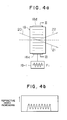
- Fig. 4a it will be explained how it is possible to regulate the tracking.
- an ultra-sonic wave (frequency F1) is applied to the surface acoustic wave device 18, at each of the two ends of which the electro-acoustic transducer 18a and the reflector 18b are disposed, respectively, by an ultra-sonic voltage source 19-1, ultra-sonic standing waves are produced within the surface acoustic wave device 18.
- the refractive index is distributed in the surface acoustic wave device, as indicated in Fig. 4b.
- such a refractive index distribution acts similarly to a diffraction grating.
- this laser light beam 20 is projected to this surface acoustic wave device, this laser light beam 20 is divided into the 0-th order diffracted light 21, which goes straight on, and the 1st order diffracted light 22.
- the refractive angle of the 1st order diffracted light 22 can be varied by varying the frequency of the ultra-sonic vibration applied to the surface acoustic wave device, it is possible to regulate the tracking of the light spot by using this 1st order diffracted light 22.
- the refractive angle used in practice is smaller than 1°.
- the intensity of the 1st order diffracted light 22 can be varied by varying the amplitude of the ultra-sonic vibration. Since there are no mechanical actions in these operations, the optical head according to this invention can be operated with a high reliability and with a short response time.
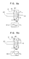
- the surface acoustic wave device 18 acts as a lens having a long focal length, and when the amplitude is great as indicated in Fig. 5b, it acts as a lens having a short focal length. In this way, by means of the device as explained above, it is possible to control the focal length without any mechanical operation by varying the amplitude of the applied ultra-sonic wave voltage.
- a surface acoustic wave device 18-1 (refer to Figs. 4a and 4b), which can vary the refractive angle of the light beam passing therethrough by using the frequency F1
- a surface acoustic wave device 18-2 (refer to Figs. 5a and 5b), which can vary the focal length for the light beam passing therethrough by varying the voltage of the vibration having a frequency F2
- the 1st order diffracted light is used for the regulation of the tracking, the incident angle and exiting angle of the light beam to and from the surface acoustic wave devices are somewhat different in practice.
- an ultra-sonic vibration of about several hundreds MHz may be used for F1 and taking into account that the total length of the surface acoustic wave device 18 is about 10 mm, an ultra-sonic vibration of about 300 - 400 kHz may be used for F2.
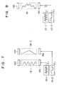
- FIG. 7 shows the operation of the embodiment indicated in Fig. 6.
- an ultra-sonic vibration (frequency F1) coming from an ultra-sonic wave source 19-1 is applied to an electro-acoustic transducer 18c of the surface acoustic wave device 18-1
- grating-shaped standing waves and consequently a grating-shaped refractive index distribution as indicated in the figure are produced between the transducer 18c an ultra-sonic reflector 18d in the surface acoustic wave device 18-1.
- the refractive angle of the 1st order diffracted light of the light beam 20 can be varied by varying the frequenzy F1 and in this way the tracking regulation of the light spot 16 can be effected.
- the grating-shaped refractive index distribution produced in the surface acoustic wave device 18-1 can be generated, apart from a standing wave, by a travelling wave of the same ultra-sonic wave.
- the ultra-sonic reflector 18d is replaced by an ultra-sonic absorber.
- the surface acoustic wave device for regulating the tracking and the surface acoustic wave device for effecting the focusing regulation are not necessarily disposed separately, as indicated in Figs. 6 and 7, but they can be united, as indicated in Fig. 8.
- the whole structure of this device is illustrated previously as an embodiment in Fig. 3.
- the standing wave produced in the surface acoustic wave device 18 is such one as the grating-shaped waves of the frequency F1 are superposed on a half period of the wave of the frequency F2.
- the ultra-sonic wave F2 for the focal point regulation can be more efficiently utilized, if it is used only in the period of time where a predetermined focusing state appears, as indicated in Figs. 9a and 9b. That is, the semiconductor laser 13 is driven by laser driving circuit 24 only in periods of time t1, t2, - - - , as indicated in Fig. 9b, by means of a synchronizing circuit 23. Furthermore, for the signal for the focusing regulation, a rectangular or trapezoidal wave, as indicated in Fig. 9c, may be used so that its flat portion drives the semiconductor laser.
- Fig. 10 shows an optical system using a photosensor 10 for the focus detection.
- the detection method is realized with a plane arrangement.
- a parallel laser light beam 20 passes through the objective lens 15 and formes the light spot on the optical disk 6. Further light reflected by the optical disk 6 passes again through the objective lens 15, is reflected at the right angle by the beam splitter 3a, and divided into two portions by another beam splitter 3b, one of them going straight on and the other being reflected at the right angle.
- the divided light beams pass through two lenses 17a and 17b, respectively, having a same focal length and are focused on photo sensors 10a and 10b.
- the photosensors 10a and 10b are so located that one of them is at a distance d1 before the correct focal point 26a and the other is at the distance d1 behind the correct focal point 26b, it is possible to detect deviations of the focal point by measuring vairations in the light intensity supplied to each of the photosensors 10a and 10b.
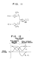
- Fig. 11 shows a circuit for processing signals coming from the photosensors 10a and 10b.
- the signals coming from the photosensours 10a and 10b are amplified by amplifiers 27a and 27b, respectively, and the difference therebetween is formed by an operational amplifier 28 so as to obtain a difference signal f+-f ⁇ .
- Fig. 12 is a graph showing the relation between the voltage of each of the signals and the position of the photosensors 10a and 10b described above. As it can be understood from this figure, it is possible to find the correctly focused position by regulating the surface acoustic wave devices so that the difference signal f+-f ⁇ is O Volt.
- a lens whose focal distance can be varied by signals given from the exterior, is mounted on an optical head using a thin film optical wave guide, a focusing and tracking actuator for laser light without any mechanical operation can be constructed, and thus it is possible to make the optical head smaller, lighter and more reliable.
Landscapes
- Physics & Mathematics (AREA)
- Optics & Photonics (AREA)
- Chemical & Material Sciences (AREA)
- Crystallography & Structural Chemistry (AREA)
- Optical Head (AREA)
Abstract
Description
- This invention relates to an optical head for recording, reproduction and erasing used in an optical disk memory system and in particular to an optical head using a thin film optical wave guide.
- As the post-industrialization progresses, the amount of information treated in the society is surely increasing. For this reason the request to increase the memory capacity of the information recording device storing this information becomes progressively stronger. As a system for recording or reproducing various sorts of information those utilizing a magnetic method or an optical method are used in practice. However, among them, an optical disk system utilizing an optical disk as a memory medium permits to store information with a density, which is more than 100 times as high as that of a prior art system utilizing a magnetic medium, and on the other hand it has an excellent feature that high quality reproduced signals can be obtained without any contact. Video disk, digital audio disk, etc. are known as memory systems utilizing such an optical recording medium.
- Fig. 1 illustrates the basic construction of an optical head used in these systems. In the figure a laser light beam emitted by a semiconductor laser device 1 is transformed into a parallel light beam by a collimator lens 2 and goes straight on through a
beam splitter 3. It passes further through a 1/4 wave plate 4 and an objective lens 5 and is focused on anoptical disk 6 so as to form alight spot 7. Thislight spot 7 is reflected by theoptical disk 6 and passes again through the objective lens 5 and the 1/4 wave plate 4. Then it passes throughcylindrical lenses 8 and 9 after having been reflected to the right angle by thebeam splitter 3, which is a half mirror, and is focussed on anoptical sensor 10. Thisoptical sensor 10 detects the focusing and the tracking information of the objective lens 5 and the presence or absence of the record on the disk. - In such an optical system, since it was necessary to regulate the position of each of optical parts so that the light spot is focused on the
optical disk 6 and theoptical sensor 10. There was a problem that the regulation necessitated a long time. Further there was another problem that the reduction of the size of the optical head on the whole was limited. - Since the reduction of the size of the optical head contributes considerably to the reduction of the size of the whole optical disk system and to the increase of the reliability, research and development therefore are at present widely promoted. As a proposition for the reduction of the size and the weight of an optical head, that disclosed by JP-A-60-202553 is known. According to this proposition, indicated in Fig. 2, an
optical wave guide 12 is formed by diffusing titanium into a surface portion several micronmeters thick of a substrate 11 made of lithium niobate (LiNbO₃) and a laser light beam emitted by a semiconductor laser light beam emitted by asemiconductor laser device 13 is projected to one end surface of thisoptical wave guide 12. Then alight spot 16 is formed by focusing it on the other end surface of theoptical wave guide 12 by means of refractive indexdistribution type lenses - This kind of techniques is summarized in the following litterature; T. SUHARA et al., "Integrated Optics Components and Devices Using Periodic Structures" IEEE J. of Quantum Electronics pp. 845 - 867, 1986.
- Since, in the prior art techniques, no attention was paid to the light spot actuate techniques, i.e. autofocusing and autotracking, in order to realize these functions, it was obliged to locate the whole optical head on a coil actuator, etc. and to move it forward and backward towards left and right. For this reason there was a problem that the construction was complicated and that the reliability of the autofocusing and the autotracking was low.
- The object of this invention is to provide an optical head using a thin film optical wave guide, which is small and light and forwhich autofocusing and autotracking of the light spot are possible.
- In order to achieve the object described above, according to this invention, a thin film optical wave guide type optical head comprising an optical system consisting of a collimetor lens, a beam splitter and an objective lens formed in the plate-shaped optical wave guide and a laser light source projecting a laser light beam to this optical system, wherein recording, reproduction and erasing of information are effected by focusing and projecting the laser light beam stated above on a optical recording medium through the optical system described above, comprises further a lens located in the proximity of the pbjective lens, whose focal distance can be varied by a signal supplied from the exterior.
- According to the construction described above, since it is possible to vary the focal point of the optical system as well as the refractive index distribution by varying the refractive index of the lens located in the proximity of the objective lens by a signal supplied from the exterior and by varying the magnitude of the refractive index in the optical wave guide, autofocusing and autotracking of the light beam can be effected without any mechanical operation.
-
- Fig. 1 is a scheme illustrating the con struction of a prior art optical head;
- Fig. 2 is a perspective view showing a prior art optical wave guide type optical head;
- Fig. 3 is a perspective view illustrating an embodiment of the optical head according to this invention;
- Figs. 4a, 4b, 5a and 5b are schemes for explaining the operation of a surface acoustic wave device in Fig. 3;
- Fig. 6 is a scheme illustrating another embodiment;
- Fig. 7 is a scheme for explaining the operationof the embodiment indicated in Fig. 6;
- Fig. 8 is a scheme for explaining the operation of the embodiment indicated in Fig. 3;
- Figs. 9a, 9b and 9c illustrate other embodiments;
- Fig. 10 is a scheme illustrating the optical system for focus error detecting means;
- Fig. 11 is a circuit diagram of the focus error detecting means; and
- Fig. 12 is a graph showing variations in the signal voltage in the focus error detecting means.
- Hereinbelow some embodiments of the optical head according to this invention will be explained, referring to the drawing.
- Fig. 3 shows an embodiment of this invention, in which the reference numerals used also in Fig. 1 or 2 represent same or corresponding items in the prior art device indicated therein. In Fig. 3, an
optical wave guide 12 is formed by diffusing titanium in a surface portion several micronmeters thick of a substrate 11 made of lithium niobate (LiNbO₃). The optical wave guide may be made of various materials other than those indicated above. The materials used therefore can be divided into two groups, one being inorganic and the other organic. The representative inorganic materials are lithium niobate (LiNbO₃), glass etc. The optical wave guide is formed by doping one of these materials with ions. (Table 1) - Various sorts of organic material may be used therefor. An optical wave guide is fabricated by applying one of them by spin coating, sputtering, etc. on an inorganic substrate such as glass, SiO₂, etc. (Table 2)


- On the other hand, geodesic lenses disposed in a recess portion formed in the form of a cercle on the
optical wave guide 12, mode index type lenses represented by a refractive index distribution type lens, in which the refractive index is distributed by implating ions therein, Fresnel lenses using diffraction, grating lenses may be used for thecollimeter lens 14, theobjective lens 15 and thephotosensor lens 17. In this embodiment a geodesic lens having a focal length of 6.5 mm is formed by a recess about 0.2 mm deep having a diameter of 7.6 mm. Concerning the geodesic lens, refer to e.g. the following article; S. Sottini et al. "Geodesic optics; new components", J. Opt. Soc. Am., pp. 1230 - 1234, 1980, which is hereby incorporated by reference. - Then the
beam splitter 3 can be constructed by forming low grooves or ridges on the surface of the optical wave guide and a part of the light in the optical wave guide is reflected, the other part being transmitted. Their ratio can be varied by varying the depth of the grooves or the height of the ridges. Refer to e.g. W.T. Tsang, et al. "Thin-film beam splitter and reflector for optical guided waves", Applied Physics Letters, pp. 588 - 590, 1970, which is hereby incorporated by reference. - On the other hand the semiconductor laser (GaAs) 13 and the photosensor (semiconductor sensor) 10 are disposed on two and surfaces of the
optical wave guide 12, respectively, which intersect perpendicularly to each other. - Further the end surface of the
optical wave guide 12 on the side, where theobjective lens 15 is disposed, is inclined with an angle of about 45° with respect to the upper surface so that the light beam leaving theobjective lens 15 is totally reflected by the inclined surface (the same principle as that of the prism) and directed to theoptical disk 6, as indicated in Fig. 3. - A surface
acoustic wave device 18, which is a feature of this embodiment, is formed on theoptical wave guide 12 between thebeam splitter 3 and theobjective lens 15. An electro-acoustic transducer (interdigital electrodes) 18a is buried and adhered at one end thereof and an ultra-sonic reflector (a reflecting electrode) 18b at the other end. - In this embodiment, since the
optical wave guide 12 is made of lithium niobate (LiNbO₃), which itself has a piezo-electric effect, the electro-acoustic transducer 18a can be constructed only by the interdigital electrodes. However, in the case where theoptical wave guide 12 is made of a substance such as glass, As₂S₃, etc., which itself has no piezo-electric effect, the electro-acoustic transducer 18a is constructed by a combination of the interdigital electrodes with a ZnO thin film, which itself has a piezo-electric effect. - Further, although a usual reflector is used as the
ultra-sonic reflector 18b in this embodiment, is it also possible to use a reflector having a construction similar to that of the electro-acoustic transducer 18a. However, in this case, it is necessary to regulate suitably the phase of the voltage applied to the two transducers. - Now the operation and the effect of this embodiment will be explained. The light beam emitted by the
semiconductor laser 13 is transformed into a parallel light beam by thecollimator lens 14, which passes through thebeam splitter 3. The position of the focusing and the position of the beam are controlled by the surfaceacoustic wave device 18 and theobjective lens 15. Then the light beam is reflected by the inclined end surface of theoptical wave guide 12 and forms thelight spot 16 on theoptical disk 6. Further the light reflected by theoptical disk 6 passes again through theobjective lens 15 and the surfaceacoustic wave device 18 and is reflected approximately at the right angle by thebeam splitter 3. Then the beam passes through thelens 17 and is finally focused on thephotosensor 10. Thisphotosensor 10 detects the state of focusing of thelight spot 7, the tracking state and presence or absence of information. - Then it will be explained how it is possible to regulate the position of the
light spot 7, i.e. to regulate the tracking and the focal length by means of the surfaceacoustic wave device 18, referring to Figs. 4a, 4b, 5a and 5b. - At first, referring to Fig. 4a, it will be explained how it is possible to regulate the tracking. When an ultra-sonic wave (frequency F₁) is applied to the surface
acoustic wave device 18, at each of the two ends of which the electro-acoustic transducer 18a and thereflector 18b are disposed, respectively, by an ultra-sonic voltage source 19-1, ultra-sonic standing waves are produced within the surfaceacoustic wave device 18. At this time, when observed in the corsssection along the line III-III in Fig. 4a, the refractive index is distributed in the surface acoustic wave device, as indicated in Fig. 4b. In case the difference between distances from two adjacent loops in the refractive index to a certain point in space is comparable with the wavelength, such a refractive index distribution acts similarly to a diffraction grating. When alaser light beam 20 is projected to this surface acoustic wave device, thislaser light beam 20 is divided into the 0-th order diffracted light 21, which goes straight on, and the 1st order diffractedlight 22. At this time, since the refractive angle of the 1st order diffracted light 22 can be varied by varying the frequency of the ultra-sonic vibration applied to the surface acoustic wave device, it is possible to regulate the tracking of the light spot by using this 1st order diffractedlight 22. The refractive angle used in practice is smaller than 1°. In addition, the intensity of the 1st order diffracted light 22 can be varied by varying the amplitude of the ultra-sonic vibration. Since there are no mechanical actions in these operations, the optical head according to this invention can be operated with a high reliability and with a short response time. - Now it will be explained how it is possible to regulate the focal length referring to Figs. 5a and 5b. In this case an ultra-sonic vibration having a frequency F₂, whose half period is just equal to the total length of the surface
acoustic wave device 18, is applied thereto. Then in the surfaceacoustic wave device 18 is produced a standing wave having a waveform corresponding to a half period of a sine curve indicated in Figs. 5a and 5b. In this way the refractive index distribution has a form corresponding to the waveform of this standing wave. Consequently the surface acoustic wave device having such a refractive index distribution acts on the light beam passing therethrough similarly to a convex lens. When the amplitude of the applied voltage is small as indicated in Fig. 5a, the surfaceacoustic wave device 18 acts as a lens having a long focal length, and when the amplitude is great as indicated in Fig. 5b, it acts as a lens having a short focal length. In this way, by means of the device as explained above, it is possible to control the focal length without any mechanical operation by varying the amplitude of the applied ultra-sonic wave voltage. - Therefore, as indicated in Fig. 6, if there are disposed a surface acoustic wave device 18-1 (refer to Figs. 4a and 4b), which can vary the refractive angle of the light beam passing therethrough by using the frequency F₁, and a surface acoustic wave device 18-2 (refer to Figs. 5a and 5b), which can vary the focal length for the light beam passing therethrough by varying the voltage of the vibration having a frequency F₂, it is possible to effect the regulation of the tracking and the focal point of the light spot without any mechanical operation. Since the 1st order diffracted light is used for the regulation of the tracking, the incident angle and exiting angle of the light beam to and from the surface acoustic wave devices are somewhat different in practice.
- Since the velocity of sound in lithium niobate (LiNbO₃) is 6.57 x 10³ m/s, an ultra-sonic vibration of about several hundreds MHz may be used for F₁ and taking into account that the total length of the surface
acoustic wave device 18 is about 10 mm, an ultra-sonic vibration of about 300 - 400 kHz may be used for F₂. - Next Fig. 7 shows the operation of the embodiment indicated in Fig. 6. At first, when an ultra-sonic vibration (frequency F₁) coming from an ultra-sonic wave source 19-1 is applied to an electro-
acoustic transducer 18c of the surface acoustic wave device 18-1, grating-shaped standing waves and consequently a grating-shaped refractive index distribution as indicated in the figure are produced between thetransducer 18c anultra-sonic reflector 18d in the surface acoustic wave device 18-1. In this case the refractive angle of the 1st order diffracted light of thelight beam 20 can be varied by varying the frequenzy F₁ and in this way the tracking regulation of thelight spot 16 can be effected. - On the other hand, when a single (frequency F₂) coming from an ultra-sonic wave source 19-2 is applied to another electro-
acoustic transducer 18e of the other surface acoustic wave device 18-2, a standing wave of a half period of a frequenzy F₂ is produced, as indicated in the figure, in a surface acoustic wave device 18-2, which gives rise to a refractive index distribution having a same waveform as that of the standing wave. In this way the refractive index of the lens for thelight beam 20 can be varied by varying the amplitude of the ultra-sonic vibration coming from the ultra-sonic wave source 19-2 and in this way the focal point regulation of thelight spot 16 can be effected. - Further, the grating-shaped refractive index distribution produced in the surface acoustic wave device 18-1 can be generated, apart from a standing wave, by a travelling wave of the same ultra-sonic wave. In this case, the
ultra-sonic reflector 18d is replaced by an ultra-sonic absorber. - The surface acoustic wave device for regulating the tracking and the surface acoustic wave device for effecting the focusing regulation are not necessarily disposed separately, as indicated in Figs. 6 and 7, but they can be united, as indicated in Fig. 8. The whole structure of this device is illustrated previously as an embodiment in Fig. 3. In this case the standing wave produced in the surface
acoustic wave device 18 is such one as the grating-shaped waves of the frequency F₁ are superposed on a half period of the wave of the frequency F₂. - Further, since the standing wave varies every moment, the ultra-sonic wave F₂ for the focal point regulation can be more efficiently utilized, if it is used only in the period of time where a predetermined focusing state appears, as indicated in Figs. 9a and 9b. That is, the
semiconductor laser 13 is driven bylaser driving circuit 24 only in periods of time t₁, t₂, - - - , as indicated in Fig. 9b, by means of a synchronizingcircuit 23. Furthermore, for the signal for the focusing regulation, a rectangular or trapezoidal wave, as indicated in Fig. 9c, may be used so that its flat portion drives the semiconductor laser. - Fig. 10 shows an optical system using a
photosensor 10 for the focus detection. In the case where theoptical wave guide 12 is used, it is difficult to arrange a 3-dimensional optical system and thus it is impossible to construct an astigmatism type focus detection method, which is widely utilized in the optical disk system. By the optical system indicated in Fig. 10 the detection method is realized with a plane arrangement. A parallellaser light beam 20 passes through theobjective lens 15 and formes the light spot on theoptical disk 6. Further light reflected by theoptical disk 6 passes again through theobjective lens 15, is reflected at the right angle by thebeam splitter 3a, and divided into two portions by anotherbeam splitter 3b, one of them going straight on and the other being reflected at the right angle. The divided light beams pass through two lenses 17a and 17b, respectively, having a same focal length and are focused onphoto sensors 10a and 10b. At this time, if thephotosensors 10a and 10b are so located that one of them is at a distance d₁ before the correctfocal point 26a and the other is at the distance d₁ behind the correctfocal point 26b, it is possible to detect deviations of the focal point by measuring vairations in the light intensity supplied to each of thephotosensors 10a and 10b. - Fig. 11 shows a circuit for processing signals coming from the
photosensors 10a and 10b. The signals coming from thephotosensours 10a and 10b are amplified byamplifiers operational amplifier 28 so as to obtain a difference signal f⁺-f⁻. Fig. 12 is a graph showing the relation between the voltage of each of the signals and the position of thephotosensors 10a and 10b described above. As it can be understood from this figure, it is possible to find the correctly focused position by regulating the surface acoustic wave devices so that the difference signal f⁺-f⁻ is O Volt. - As explained above, according to this invention, since a lens, whose focal distance can be varied by signals given from the exterior, is mounted on an optical head using a thin film optical wave guide, a focusing and tracking actuator for laser light without any mechanical operation can be constructed, and thus it is possible to make the optical head smaller, lighter and more reliable.
Claims (15)
a plate-shaped optical wave guide (12) having at least three end surfaces, said optical wave guide being formed of a material, which is capable of establishing condensation and rarefaction in refractive index by a surface acoustic wave, and said optical wave guide being provided with an optical system including a collimator lens (14), a beam splitter (3) and an objective lens (15) and a sensor lens (17) located besides the beam splitter (3);
a laser light source (13) disposed at one of the end surfaces of said optical wave guide (12) for emitting a laser light beam, light emitted by said laser light source (13) adapted to be directed in the form of a light beam to said optical recording medium (6);
electro-acoustic transducer (18a, 18b, 18c, 18d, 18e, 18f) disposed between said beam splitter (3) and said objective lens (15), said transducer being adapted to be driven by ultra-sonic vibration for producing surface acoustic wave in said optical wave guide (12), which gives rise to a condensation and rarefaction distribution in refractive index in said optical wave guide (12) influencing the direction of transmission of said light beam passing therethrough;
a semiconductor photosensor (10) disposed at another end surface of said optical wave guide (12) in opposition to said sensor lens (17), said photosensor (10) detecting reflected light of said light beam projected and focused on said optical recording medium in cooperation said objective lens (15), said beam splitter (3) and said sensor lens (17); and
means for regulating said ultra-sonic vibration, depending on the output of said photsensor (10).
a plate-shaped optical wave guide (12) having at least one end surfaces, said optical wave guide being formed of a material, which is capable of establishing condensation and rarefaction in refractive index by a surface acoustic wave, and said optical wave guide being provided with an optical system including a collimator lens (14) and an objective lens (15);
a laser light source (13) disposed at one of the end surfaces of said optical wave guide (12) for emitting a laser light beam, light emitted by said laser light source (13) adapted to be directed in the form of a light beam to said optical recording medium (6); and
electro-acoustic transducer (18e, 18f) disposed between said beam splitter (3) and said objective lens (15), said transducer being adapted to be driven by ultra-sonic vibration for producing a standing wave of an ultra-sonic surface acoustic wave corresponding to a half period of a sine curve, across a path of said light beam formed in said optical wave guide (12), which gives rist to a form of the half period of a sine curve condensation and rarefraction distribution in refractive index in said optical wave guide (12), thereby giving a function of lens for the light beam passing therethrough with a variable focal position controlled by varying the amplitude of said ultra-sonic vibration.
a plate-shaped optical wave guide (12) having at least one end surfaces, said optical wave guide being formed of a material which is capable of establishing condensation and rarefaction in refractive index by a surface acoustic wave, and an optical wave guide being provided with an optical system including a collimator lens (14) and an objective lens (15);
a laser light source (13) disposed at one of the end surfaces of said optical wave guide (12) for exmitting a laser light beam, light emitted by said laser light source (13) adapted to be directed in the form of a light beam to said optical recording medium (6);
first electro-acoustic transducer (18e, 18f) disposed between said beam splitter (3) and said objective lens (15), said transducer being adapted to be driven by a first ultra-sonic vibration for producing a standing wave of an ultra-sonic surface acoustic wave corresponding to a half period of a sine curve, across a path of said light beam formed in said optical wave guide (12), which gives rise to a form of the half period of a sine curve condensation and rarefaction distributyion in refractive index in said optical wave guide (12), thereby giving a function of lens for the light beam passing therethough with avariable focal position controlled by varying the amplitude of said ultra-sonic vibration; and
second electro-acoustic transducer (18c, 18d) disposed between said beam splitter (3) and said objective lens (15), said transducer being adpated to be driven by a second ultra-sonic vibration for producing ultra-sonic surface acoustic waves across a path of said light beam formed in said optical wave guide (2), which gives rise to a form of grating-pattern condensation and rarefaction distribution in refractive index in said optical wave guide (12), thereby giving a function of diffracting grating for the light beam passing therethrough, the direction of transmission of said light beam being able to be varied, by varying the frequency of said second ultra-sonic vibration.
a plate-shaped optical wave guide (12) having at least one end surfaces, said optical wave guide being formed of a material which is capable of establishing condensation and rarefaction in refractive index by a surface acoustic wave, and said optical wave guide being provided with an optical system including a collimator lens (14) and an objective lens (15);
a laser light source (13) disposed at one of the end surfaces of said optical wave guide (12) for emitting a laser light beam, light emitted by said laser light source (13) adapted to be directed in the form of a light beam to said optical recording medium (6); and
electro-acoustic transducer (18a, 18b) disposed between said beam splitter (3) and said objective lens (15),
said transducer being adapted to be driven by a first ultra-sonic vibration for producing a standing wave of an ultra-sonic surface acoustic wave corresponding to a half period of a sine curve, across a path of said light beam formed in said optical wave guide (12), which gives rise to a form of the half period of a sine curve condensation and rarefaction distribution in refractive index in said optical wave guide (12), thereby giving a function of lens for the light beam passing therethrough with a variable focal position controlled by varying the amplitude of said ultra-sonic vibration, and
said transducer being adapted to be driven by a second ultra-sonic vibration for producing ultra-sonic surface acoustic waves across a path of said light beam formed in said optical wave guide (12), which gives rise to a form of grating-pattern condensation and rarefaction distribution in refractive index in said optical wave guide (12), thereby giving a function of diffracting grating for the light beam passing therethrough, the direction of transmission of said light beam being able to be varied, by varying the frequency of said second ultra-sonic vibration.
a plate-shaped optical wave guide (12), said optical wave guide being formed of a material which is capable of establishing a condensation and rarefaction distribution in refractive index by a surface acoustic wave;
electro-acoustic transducer (18e, 18f) located to produce a surface acoustic wave which transverses an optical path in said optical wave guide (12);
ultra-sonic wave generator (19-2) driving said electro-acoustic transducer (18e, 18f), said transducer being adapted to be driven by ultra-sonic vibration for producing a standing wave of an ultra-sonic surface acoustic wave corresponding to a half period of a sine curve, across said optical path in said optical wave guide (12), which gives rise to a form of the half period of a sine wave condensation and rarefaction distribution in refractive index in sais optical wave guide (12), the distribution acting on the light beam passing therethrough as a lens with a variable focal position controlled by varying the amplitude of said ultra-sonic vibration.
Applications Claiming Priority (2)
| Application Number | Priority Date | Filing Date | Title |
|---|---|---|---|
| JP212312/86 | 1986-09-09 | ||
| JP21231286 | 1986-09-09 |
Publications (2)
| Publication Number | Publication Date |
|---|---|
| EP0259832A2 true EP0259832A2 (en) | 1988-03-16 |
| EP0259832A3 EP0259832A3 (en) | 1989-03-15 |
Family
ID=16620470
Family Applications (1)
| Application Number | Title | Priority Date | Filing Date |
|---|---|---|---|
| EP87113110A Withdrawn EP0259832A3 (en) | 1986-09-09 | 1987-09-08 | Optical head |
Country Status (2)
| Country | Link |
|---|---|
| US (1) | US4862440A (en) |
| EP (1) | EP0259832A3 (en) |
Cited By (3)
| Publication number | Priority date | Publication date | Assignee | Title |
|---|---|---|---|---|
| WO1988010493A1 (en) * | 1987-06-15 | 1988-12-29 | Eastman Kodak Company | Integrated optical read/write head and apparatus incorporating same |
| EP0360209A2 (en) * | 1988-09-19 | 1990-03-28 | Hitachi, Ltd. | Optical head and optical data processing apparatus |
| US5070488A (en) * | 1988-06-29 | 1991-12-03 | Atsuko Fukushima | Optical integrated circuit and optical apparatus |
Families Citing this family (10)
| Publication number | Priority date | Publication date | Assignee | Title |
|---|---|---|---|---|
| JP2565265B2 (en) * | 1987-11-28 | 1996-12-18 | ソニー株式会社 | Optical information processing device |
| DE69024635T2 (en) * | 1989-10-14 | 1996-05-30 | Copal Co Ltd | Optical scanning unit with focus adjustment arrangement |
| US5235591A (en) * | 1990-01-19 | 1993-08-10 | Hitachi, Ltd. | Stack type optical disc apparatus, sealed and separate type optical head therefor and optical disc medium |
| US5144603A (en) * | 1990-03-07 | 1992-09-01 | Hitachi, Ltd. | Optical head incorporating refractive index distribution changeable lens |
| JP3131994B2 (en) * | 1990-11-07 | 2001-02-05 | パイオニア株式会社 | Recorded information reading device |
| US5233582A (en) * | 1991-02-19 | 1993-08-03 | Pioneer Electronic Corporation | Optical waveguide recording medium playing apparatus |
| US5251193A (en) * | 1991-09-24 | 1993-10-05 | Nelson Jonathan B | Solid state optical disk reader |
| US6776176B1 (en) * | 2000-05-26 | 2004-08-17 | Terastor Corporation | Applications of acoustic waves in data storage devices |
| DE10113788A1 (en) * | 2001-03-21 | 2002-09-26 | Zeiss Carl | Diffraction optical component, illumination system and exposure system with such a diffraction optical component and exposure method using such an exposure system |
| US9489973B2 (en) | 2013-02-13 | 2016-11-08 | Oregon State University | Magnetic data storage using induced strain of a magnetostrictive material |
Citations (2)
| Publication number | Priority date | Publication date | Assignee | Title |
|---|---|---|---|---|
| DE3534776A1 (en) * | 1984-10-01 | 1986-04-10 | Mitsubishi Denki K.K., Tokio/Tokyo | HEAD ARRANGEMENT FOR AN OPTICAL DISC |
| JPS6289250A (en) * | 1985-10-16 | 1987-04-23 | Fuji Photo Film Co Ltd | Pickup for optical disk |
Family Cites Families (5)
| Publication number | Priority date | Publication date | Assignee | Title |
|---|---|---|---|---|
| US4747090A (en) * | 1982-10-14 | 1988-05-24 | Omron Tateisi Electronics Co. | Integral pickup for an optical digital disc using saw deflection and lenses |
| JPS59107431A (en) * | 1982-12-10 | 1984-06-21 | Omron Tateisi Electronics Co | Pickup for optical digital disk |
| US4720824A (en) * | 1984-12-28 | 1988-01-19 | Olympus Optical Co., Ltd. | Information reading apparatus with a light beam scanning technique |
| US4779259A (en) * | 1985-04-25 | 1988-10-18 | Mitsubishi Denki Kabushiki Kaisha | Optical head assembly with efficient light source coupling surface and method of construction |
| JPS6273437A (en) * | 1985-09-26 | 1987-04-04 | Mitsubishi Electric Corp | Optical head device |
-
1987
- 1987-09-08 EP EP87113110A patent/EP0259832A3/en not_active Withdrawn
- 1987-09-09 US US07/098,969 patent/US4862440A/en not_active Expired - Fee Related
Patent Citations (2)
| Publication number | Priority date | Publication date | Assignee | Title |
|---|---|---|---|---|
| DE3534776A1 (en) * | 1984-10-01 | 1986-04-10 | Mitsubishi Denki K.K., Tokio/Tokyo | HEAD ARRANGEMENT FOR AN OPTICAL DISC |
| JPS6289250A (en) * | 1985-10-16 | 1987-04-23 | Fuji Photo Film Co Ltd | Pickup for optical disk |
Non-Patent Citations (3)
| Title |
|---|
| PATENT ABSTRACTS OF JAPAN, vol. 8, no. 192 (P-298)[1629], 4th September 1984; & JP-A-59 79 441 (TATEISHI DENKI K.K.) 08-05-1984 * |
| PATENT ABSTRACTS OF JAPAN, vol. 8, no. 228 (P-308)[1665], 19th October 1984; & JP-A-59 107 431 (TATEISHI DENKI K.K.) 21-06-1984 * |
| PATENT ABSTRACTS OF JAPAN, vol. 9, no. 292 (P-406)[2015], 19th November 1985; & JP-A-60 129 938 (HITACHI SEISAKUSHO K.K.) 11-07-1985 * |
Cited By (4)
| Publication number | Priority date | Publication date | Assignee | Title |
|---|---|---|---|---|
| WO1988010493A1 (en) * | 1987-06-15 | 1988-12-29 | Eastman Kodak Company | Integrated optical read/write head and apparatus incorporating same |
| US5070488A (en) * | 1988-06-29 | 1991-12-03 | Atsuko Fukushima | Optical integrated circuit and optical apparatus |
| EP0360209A2 (en) * | 1988-09-19 | 1990-03-28 | Hitachi, Ltd. | Optical head and optical data processing apparatus |
| EP0360209A3 (en) * | 1988-09-19 | 1992-08-19 | Hitachi, Ltd. | Optical head and optical data processing apparatus |
Also Published As
| Publication number | Publication date |
|---|---|
| US4862440A (en) | 1989-08-29 |
| EP0259832A3 (en) | 1989-03-15 |
Similar Documents
| Publication | Publication Date | Title |
|---|---|---|
| EP0259832A2 (en) | Optical head | |
| JPS6235168B2 (en) | ||
| US5953294A (en) | Optical pickup apparatus | |
| GB2169119A (en) | Information reading apparatus | |
| JPH0743843B2 (en) | Optical reader | |
| US4977552A (en) | Split type optical pick-up device with a tracking error detector on the moving part | |
| US5428584A (en) | Pickup device for a magneto-optical information recording system | |
| EP0740295A1 (en) | Optical pickup apparatus and optical disk drive apparatus | |
| US5058091A (en) | Optical pickup device | |
| EP0766236B1 (en) | Optical head device with optically variable aperture | |
| JP2594970B2 (en) | Thin-film optical waveguide type optical head | |
| JPS61216128A (en) | Optical disk device | |
| JPH0628704A (en) | Optical head device | |
| US4569039A (en) | Optical information output device | |
| JPS61294646A (en) | Integrated optical head | |
| JP2656036B2 (en) | Light head | |
| JPS63247925A (en) | Optical head | |
| JPH0793797A (en) | Optical head and disk device using the same | |
| KR970005986B1 (en) | Optical pick-up device | |
| KR100595509B1 (en) | Base optical unit in optical disk player | |
| JPH0219537B2 (en) | ||
| JP2501097B2 (en) | Optical head device | |
| JP2615556B2 (en) | Tracking servo device | |
| JP2594957B2 (en) | Optical recording / reproducing device | |
| JPH0673202B2 (en) | Magneto-optical reproducing device |
Legal Events
| Date | Code | Title | Description |
|---|---|---|---|
| PUAI | Public reference made under article 153(3) epc to a published international application that has entered the european phase |
Free format text: ORIGINAL CODE: 0009012 |
|
| 17P | Request for examination filed |
Effective date: 19870908 |
|
| AK | Designated contracting states |
Kind code of ref document: A2 Designated state(s): CH DE FR GB IT LI NL SE |
|
| PUAL | Search report despatched |
Free format text: ORIGINAL CODE: 0009013 |
|
| AK | Designated contracting states |
Kind code of ref document: A3 Designated state(s): CH DE FR GB IT LI NL SE |
|
| 17Q | First examination report despatched |
Effective date: 19901120 |
|
| STAA | Information on the status of an ep patent application or granted ep patent |
Free format text: STATUS: THE APPLICATION HAS BEEN WITHDRAWN |
|
| 18W | Application withdrawn |
Withdrawal date: 19920313 |
|
| RIN1 | Information on inventor provided before grant (corrected) |
Inventor name: TSUBOI, NOBUYOSHI Inventor name: SASAKI, HIROSHI Inventor name: KOYANAGI, HIROAKI Inventor name: MINEMURA, HIROYUKI Inventor name: MIYAMOTO, NORIFUMI Inventor name: SATO, YOSHIO Inventor name: SHIMADA, SATOSHI |