EP0252455A2 - Régulation d'un système de refroidissement à composant multiples pour la liquéfaction de gaz naturel - Google Patents
Régulation d'un système de refroidissement à composant multiples pour la liquéfaction de gaz naturel Download PDFInfo
- Publication number
- EP0252455A2 EP0252455A2 EP87109630A EP87109630A EP0252455A2 EP 0252455 A2 EP0252455 A2 EP 0252455A2 EP 87109630 A EP87109630 A EP 87109630A EP 87109630 A EP87109630 A EP 87109630A EP 0252455 A2 EP0252455 A2 EP 0252455A2
- Authority
- EP
- European Patent Office
- Prior art keywords
- production rate
- mixed refrigerant
- facility
- production
- rate
- Prior art date
- Legal status (The legal status is an assumption and is not a legal conclusion. Google has not performed a legal analysis and makes no representation as to the accuracy of the status listed.)
- Granted
Links
- VNWKTOKETHGBQD-UHFFFAOYSA-N methane Chemical compound C VNWKTOKETHGBQD-UHFFFAOYSA-N 0.000 title claims abstract description 27
- 239000003345 natural gas Substances 0.000 title claims description 6
- 238000005057 refrigeration Methods 0.000 title description 3
- 238000004519 manufacturing process Methods 0.000 claims abstract description 150
- 239000003507 refrigerant Substances 0.000 claims abstract description 46
- 239000000203 mixture Substances 0.000 claims abstract description 30
- 238000005457 optimization Methods 0.000 claims abstract description 18
- 230000006835 compression Effects 0.000 claims abstract description 14
- 238000007906 compression Methods 0.000 claims abstract description 14
- 238000012544 monitoring process Methods 0.000 claims abstract description 8
- 238000000034 method Methods 0.000 claims description 66
- 239000000446 fuel Substances 0.000 claims description 36
- 239000007788 liquid Substances 0.000 claims description 21
- 238000013461 design Methods 0.000 claims description 20
- 239000003949 liquefied natural gas Substances 0.000 claims description 19
- IJGRMHOSHXDMSA-UHFFFAOYSA-N Atomic nitrogen Chemical compound N#N IJGRMHOSHXDMSA-UHFFFAOYSA-N 0.000 claims description 12
- 230000003247 decreasing effect Effects 0.000 claims description 7
- 229910052757 nitrogen Inorganic materials 0.000 claims description 6
- 238000002347 injection Methods 0.000 claims description 4
- 239000007924 injection Substances 0.000 claims description 4
- 230000008859 change Effects 0.000 claims description 3
- 238000013022 venting Methods 0.000 claims 1
- 230000006870 function Effects 0.000 abstract description 19
- 230000008569 process Effects 0.000 description 40
- 238000010438 heat treatment Methods 0.000 description 14
- 238000012545 processing Methods 0.000 description 11
- 230000000875 corresponding effect Effects 0.000 description 6
- 239000007789 gas Substances 0.000 description 6
- 238000010586 diagram Methods 0.000 description 5
- 230000000694 effects Effects 0.000 description 5
- ATUOYWHBWRKTHZ-UHFFFAOYSA-N Propane Chemical compound CCC ATUOYWHBWRKTHZ-UHFFFAOYSA-N 0.000 description 4
- 238000007726 management method Methods 0.000 description 4
- 238000001914 filtration Methods 0.000 description 3
- 238000010304 firing Methods 0.000 description 3
- 230000004044 response Effects 0.000 description 3
- 238000003860 storage Methods 0.000 description 3
- 230000003466 anti-cipated effect Effects 0.000 description 2
- 238000004364 calculation method Methods 0.000 description 2
- 238000005265 energy consumption Methods 0.000 description 2
- 238000012913 prioritisation Methods 0.000 description 2
- 239000001294 propane Substances 0.000 description 2
- 238000012360 testing method Methods 0.000 description 2
- 239000004215 Carbon black (E152) Substances 0.000 description 1
- OTMSDBZUPAUEDD-UHFFFAOYSA-N Ethane Chemical compound CC OTMSDBZUPAUEDD-UHFFFAOYSA-N 0.000 description 1
- 238000004458 analytical method Methods 0.000 description 1
- 238000013459 approach Methods 0.000 description 1
- 238000004587 chromatography analysis Methods 0.000 description 1
- 238000004891 communication Methods 0.000 description 1
- 230000001276 controlling effect Effects 0.000 description 1
- 230000002596 correlated effect Effects 0.000 description 1
- 238000013016 damping Methods 0.000 description 1
- 230000007547 defect Effects 0.000 description 1
- 230000001934 delay Effects 0.000 description 1
- 230000007613 environmental effect Effects 0.000 description 1
- 229930195733 hydrocarbon Natural products 0.000 description 1
- 150000002430 hydrocarbons Chemical class 0.000 description 1
- 238000010348 incorporation Methods 0.000 description 1
- 238000009434 installation Methods 0.000 description 1
- 230000010354 integration Effects 0.000 description 1
- 230000002452 interceptive effect Effects 0.000 description 1
- 230000007246 mechanism Effects 0.000 description 1
- 238000012986 modification Methods 0.000 description 1
- 230000004048 modification Effects 0.000 description 1
- 238000011017 operating method Methods 0.000 description 1
- 238000004886 process control Methods 0.000 description 1
- 230000007420 reactivation Effects 0.000 description 1
- 238000011084 recovery Methods 0.000 description 1
- 230000009467 reduction Effects 0.000 description 1
- 238000012546 transfer Methods 0.000 description 1
- XLYOFNOQVPJJNP-UHFFFAOYSA-N water Substances O XLYOFNOQVPJJNP-UHFFFAOYSA-N 0.000 description 1
Images


Classifications
-
- F—MECHANICAL ENGINEERING; LIGHTING; HEATING; WEAPONS; BLASTING
- F25—REFRIGERATION OR COOLING; COMBINED HEATING AND REFRIGERATION SYSTEMS; HEAT PUMP SYSTEMS; MANUFACTURE OR STORAGE OF ICE; LIQUEFACTION SOLIDIFICATION OF GASES
- F25J—LIQUEFACTION, SOLIDIFICATION OR SEPARATION OF GASES OR GASEOUS OR LIQUEFIED GASEOUS MIXTURES BY PRESSURE AND COLD TREATMENT OR BY BRINGING THEM INTO THE SUPERCRITICAL STATE
- F25J1/00—Processes or apparatus for liquefying or solidifying gases or gaseous mixtures
- F25J1/02—Processes or apparatus for liquefying or solidifying gases or gaseous mixtures requiring the use of refrigeration, e.g. of helium or hydrogen ; Details and kind of the refrigeration system used; Integration with other units or processes; Controlling aspects of the process
- F25J1/0243—Start-up or control of the process; Details of the apparatus used; Details of the refrigerant compression system used
- F25J1/0244—Operation; Control and regulation; Instrumentation
- F25J1/0245—Different modes, i.e. 'runs', of operation; Process control
-
- F—MECHANICAL ENGINEERING; LIGHTING; HEATING; WEAPONS; BLASTING
- F25—REFRIGERATION OR COOLING; COMBINED HEATING AND REFRIGERATION SYSTEMS; HEAT PUMP SYSTEMS; MANUFACTURE OR STORAGE OF ICE; LIQUEFACTION SOLIDIFICATION OF GASES
- F25J—LIQUEFACTION, SOLIDIFICATION OR SEPARATION OF GASES OR GASEOUS OR LIQUEFIED GASEOUS MIXTURES BY PRESSURE AND COLD TREATMENT OR BY BRINGING THEM INTO THE SUPERCRITICAL STATE
- F25J1/00—Processes or apparatus for liquefying or solidifying gases or gaseous mixtures
- F25J1/0002—Processes or apparatus for liquefying or solidifying gases or gaseous mixtures characterised by the fluid to be liquefied
- F25J1/0022—Hydrocarbons, e.g. natural gas
-
- F—MECHANICAL ENGINEERING; LIGHTING; HEATING; WEAPONS; BLASTING
- F25—REFRIGERATION OR COOLING; COMBINED HEATING AND REFRIGERATION SYSTEMS; HEAT PUMP SYSTEMS; MANUFACTURE OR STORAGE OF ICE; LIQUEFACTION SOLIDIFICATION OF GASES
- F25J—LIQUEFACTION, SOLIDIFICATION OR SEPARATION OF GASES OR GASEOUS OR LIQUEFIED GASEOUS MIXTURES BY PRESSURE AND COLD TREATMENT OR BY BRINGING THEM INTO THE SUPERCRITICAL STATE
- F25J1/00—Processes or apparatus for liquefying or solidifying gases or gaseous mixtures
- F25J1/003—Processes or apparatus for liquefying or solidifying gases or gaseous mixtures characterised by the kind of cold generation within the liquefaction unit for compensating heat leaks and liquid production
- F25J1/0047—Processes or apparatus for liquefying or solidifying gases or gaseous mixtures characterised by the kind of cold generation within the liquefaction unit for compensating heat leaks and liquid production using an "external" refrigerant stream in a closed vapor compression cycle
- F25J1/0052—Processes or apparatus for liquefying or solidifying gases or gaseous mixtures characterised by the kind of cold generation within the liquefaction unit for compensating heat leaks and liquid production using an "external" refrigerant stream in a closed vapor compression cycle by vaporising a liquid refrigerant stream
- F25J1/0055—Processes or apparatus for liquefying or solidifying gases or gaseous mixtures characterised by the kind of cold generation within the liquefaction unit for compensating heat leaks and liquid production using an "external" refrigerant stream in a closed vapor compression cycle by vaporising a liquid refrigerant stream originating from an incorporated cascade
-
- F—MECHANICAL ENGINEERING; LIGHTING; HEATING; WEAPONS; BLASTING
- F25—REFRIGERATION OR COOLING; COMBINED HEATING AND REFRIGERATION SYSTEMS; HEAT PUMP SYSTEMS; MANUFACTURE OR STORAGE OF ICE; LIQUEFACTION SOLIDIFICATION OF GASES
- F25J—LIQUEFACTION, SOLIDIFICATION OR SEPARATION OF GASES OR GASEOUS OR LIQUEFIED GASEOUS MIXTURES BY PRESSURE AND COLD TREATMENT OR BY BRINGING THEM INTO THE SUPERCRITICAL STATE
- F25J1/00—Processes or apparatus for liquefying or solidifying gases or gaseous mixtures
- F25J1/006—Processes or apparatus for liquefying or solidifying gases or gaseous mixtures characterised by the refrigerant fluid used
- F25J1/008—Hydrocarbons
- F25J1/0087—Propane; Propylene
-
- F—MECHANICAL ENGINEERING; LIGHTING; HEATING; WEAPONS; BLASTING
- F25—REFRIGERATION OR COOLING; COMBINED HEATING AND REFRIGERATION SYSTEMS; HEAT PUMP SYSTEMS; MANUFACTURE OR STORAGE OF ICE; LIQUEFACTION SOLIDIFICATION OF GASES
- F25J—LIQUEFACTION, SOLIDIFICATION OR SEPARATION OF GASES OR GASEOUS OR LIQUEFIED GASEOUS MIXTURES BY PRESSURE AND COLD TREATMENT OR BY BRINGING THEM INTO THE SUPERCRITICAL STATE
- F25J1/00—Processes or apparatus for liquefying or solidifying gases or gaseous mixtures
- F25J1/02—Processes or apparatus for liquefying or solidifying gases or gaseous mixtures requiring the use of refrigeration, e.g. of helium or hydrogen ; Details and kind of the refrigeration system used; Integration with other units or processes; Controlling aspects of the process
- F25J1/0211—Processes or apparatus for liquefying or solidifying gases or gaseous mixtures requiring the use of refrigeration, e.g. of helium or hydrogen ; Details and kind of the refrigeration system used; Integration with other units or processes; Controlling aspects of the process using a multi-component refrigerant [MCR] fluid in a closed vapor compression cycle
- F25J1/0214—Processes or apparatus for liquefying or solidifying gases or gaseous mixtures requiring the use of refrigeration, e.g. of helium or hydrogen ; Details and kind of the refrigeration system used; Integration with other units or processes; Controlling aspects of the process using a multi-component refrigerant [MCR] fluid in a closed vapor compression cycle as a dual level refrigeration cascade with at least one MCR cycle
- F25J1/0215—Processes or apparatus for liquefying or solidifying gases or gaseous mixtures requiring the use of refrigeration, e.g. of helium or hydrogen ; Details and kind of the refrigeration system used; Integration with other units or processes; Controlling aspects of the process using a multi-component refrigerant [MCR] fluid in a closed vapor compression cycle as a dual level refrigeration cascade with at least one MCR cycle with one SCR cycle
- F25J1/0216—Processes or apparatus for liquefying or solidifying gases or gaseous mixtures requiring the use of refrigeration, e.g. of helium or hydrogen ; Details and kind of the refrigeration system used; Integration with other units or processes; Controlling aspects of the process using a multi-component refrigerant [MCR] fluid in a closed vapor compression cycle as a dual level refrigeration cascade with at least one MCR cycle with one SCR cycle using a C3 pre-cooling cycle
-
- F—MECHANICAL ENGINEERING; LIGHTING; HEATING; WEAPONS; BLASTING
- F25—REFRIGERATION OR COOLING; COMBINED HEATING AND REFRIGERATION SYSTEMS; HEAT PUMP SYSTEMS; MANUFACTURE OR STORAGE OF ICE; LIQUEFACTION SOLIDIFICATION OF GASES
- F25J—LIQUEFACTION, SOLIDIFICATION OR SEPARATION OF GASES OR GASEOUS OR LIQUEFIED GASEOUS MIXTURES BY PRESSURE AND COLD TREATMENT OR BY BRINGING THEM INTO THE SUPERCRITICAL STATE
- F25J1/00—Processes or apparatus for liquefying or solidifying gases or gaseous mixtures
- F25J1/02—Processes or apparatus for liquefying or solidifying gases or gaseous mixtures requiring the use of refrigeration, e.g. of helium or hydrogen ; Details and kind of the refrigeration system used; Integration with other units or processes; Controlling aspects of the process
- F25J1/0228—Coupling of the liquefaction unit to other units or processes, so-called integrated processes
- F25J1/0229—Integration with a unit for using hydrocarbons, e.g. consuming hydrocarbons as feed stock
- F25J1/023—Integration with a unit for using hydrocarbons, e.g. consuming hydrocarbons as feed stock for the combustion as fuels, i.e. integration with the fuel gas system
-
- F—MECHANICAL ENGINEERING; LIGHTING; HEATING; WEAPONS; BLASTING
- F25—REFRIGERATION OR COOLING; COMBINED HEATING AND REFRIGERATION SYSTEMS; HEAT PUMP SYSTEMS; MANUFACTURE OR STORAGE OF ICE; LIQUEFACTION SOLIDIFICATION OF GASES
- F25J—LIQUEFACTION, SOLIDIFICATION OR SEPARATION OF GASES OR GASEOUS OR LIQUEFIED GASEOUS MIXTURES BY PRESSURE AND COLD TREATMENT OR BY BRINGING THEM INTO THE SUPERCRITICAL STATE
- F25J1/00—Processes or apparatus for liquefying or solidifying gases or gaseous mixtures
- F25J1/02—Processes or apparatus for liquefying or solidifying gases or gaseous mixtures requiring the use of refrigeration, e.g. of helium or hydrogen ; Details and kind of the refrigeration system used; Integration with other units or processes; Controlling aspects of the process
- F25J1/0228—Coupling of the liquefaction unit to other units or processes, so-called integrated processes
- F25J1/0235—Heat exchange integration
- F25J1/0237—Heat exchange integration integrating refrigeration provided for liquefaction and purification/treatment of the gas to be liquefied, e.g. heavy hydrocarbon removal from natural gas
- F25J1/0239—Purification or treatment step being integrated between two refrigeration cycles of a refrigeration cascade, i.e. first cycle providing feed gas cooling and second cycle providing overhead gas cooling
- F25J1/0241—Purification or treatment step being integrated between two refrigeration cycles of a refrigeration cascade, i.e. first cycle providing feed gas cooling and second cycle providing overhead gas cooling wherein the overhead cooling comprises providing reflux for a fractionation step
-
- F—MECHANICAL ENGINEERING; LIGHTING; HEATING; WEAPONS; BLASTING
- F25—REFRIGERATION OR COOLING; COMBINED HEATING AND REFRIGERATION SYSTEMS; HEAT PUMP SYSTEMS; MANUFACTURE OR STORAGE OF ICE; LIQUEFACTION SOLIDIFICATION OF GASES
- F25J—LIQUEFACTION, SOLIDIFICATION OR SEPARATION OF GASES OR GASEOUS OR LIQUEFIED GASEOUS MIXTURES BY PRESSURE AND COLD TREATMENT OR BY BRINGING THEM INTO THE SUPERCRITICAL STATE
- F25J1/00—Processes or apparatus for liquefying or solidifying gases or gaseous mixtures
- F25J1/02—Processes or apparatus for liquefying or solidifying gases or gaseous mixtures requiring the use of refrigeration, e.g. of helium or hydrogen ; Details and kind of the refrigeration system used; Integration with other units or processes; Controlling aspects of the process
- F25J1/0243—Start-up or control of the process; Details of the apparatus used; Details of the refrigerant compression system used
- F25J1/0244—Operation; Control and regulation; Instrumentation
- F25J1/0245—Different modes, i.e. 'runs', of operation; Process control
- F25J1/0249—Controlling refrigerant inventory, i.e. composition or quantity
-
- F—MECHANICAL ENGINEERING; LIGHTING; HEATING; WEAPONS; BLASTING
- F25—REFRIGERATION OR COOLING; COMBINED HEATING AND REFRIGERATION SYSTEMS; HEAT PUMP SYSTEMS; MANUFACTURE OR STORAGE OF ICE; LIQUEFACTION SOLIDIFICATION OF GASES
- F25J—LIQUEFACTION, SOLIDIFICATION OR SEPARATION OF GASES OR GASEOUS OR LIQUEFIED GASEOUS MIXTURES BY PRESSURE AND COLD TREATMENT OR BY BRINGING THEM INTO THE SUPERCRITICAL STATE
- F25J1/00—Processes or apparatus for liquefying or solidifying gases or gaseous mixtures
- F25J1/02—Processes or apparatus for liquefying or solidifying gases or gaseous mixtures requiring the use of refrigeration, e.g. of helium or hydrogen ; Details and kind of the refrigeration system used; Integration with other units or processes; Controlling aspects of the process
- F25J1/0243—Start-up or control of the process; Details of the apparatus used; Details of the refrigerant compression system used
- F25J1/0244—Operation; Control and regulation; Instrumentation
- F25J1/0252—Control strategy, e.g. advanced process control or dynamic modeling
-
- F—MECHANICAL ENGINEERING; LIGHTING; HEATING; WEAPONS; BLASTING
- F25—REFRIGERATION OR COOLING; COMBINED HEATING AND REFRIGERATION SYSTEMS; HEAT PUMP SYSTEMS; MANUFACTURE OR STORAGE OF ICE; LIQUEFACTION SOLIDIFICATION OF GASES
- F25J—LIQUEFACTION, SOLIDIFICATION OR SEPARATION OF GASES OR GASEOUS OR LIQUEFIED GASEOUS MIXTURES BY PRESSURE AND COLD TREATMENT OR BY BRINGING THEM INTO THE SUPERCRITICAL STATE
- F25J1/00—Processes or apparatus for liquefying or solidifying gases or gaseous mixtures
- F25J1/02—Processes or apparatus for liquefying or solidifying gases or gaseous mixtures requiring the use of refrigeration, e.g. of helium or hydrogen ; Details and kind of the refrigeration system used; Integration with other units or processes; Controlling aspects of the process
- F25J1/0243—Start-up or control of the process; Details of the apparatus used; Details of the refrigerant compression system used
- F25J1/0257—Construction and layout of liquefaction equipments, e.g. valves, machines
- F25J1/0262—Details of the cold heat exchange system
- F25J1/0264—Arrangement of heat exchanger cores in parallel with different functions, e.g. different cooling streams
- F25J1/0265—Arrangement of heat exchanger cores in parallel with different functions, e.g. different cooling streams comprising cores associated exclusively with the cooling of a refrigerant stream, e.g. for auto-refrigeration or economizer
- F25J1/0267—Arrangement of heat exchanger cores in parallel with different functions, e.g. different cooling streams comprising cores associated exclusively with the cooling of a refrigerant stream, e.g. for auto-refrigeration or economizer using flash gas as heat sink
-
- F—MECHANICAL ENGINEERING; LIGHTING; HEATING; WEAPONS; BLASTING
- F25—REFRIGERATION OR COOLING; COMBINED HEATING AND REFRIGERATION SYSTEMS; HEAT PUMP SYSTEMS; MANUFACTURE OR STORAGE OF ICE; LIQUEFACTION SOLIDIFICATION OF GASES
- F25J—LIQUEFACTION, SOLIDIFICATION OR SEPARATION OF GASES OR GASEOUS OR LIQUEFIED GASEOUS MIXTURES BY PRESSURE AND COLD TREATMENT OR BY BRINGING THEM INTO THE SUPERCRITICAL STATE
- F25J1/00—Processes or apparatus for liquefying or solidifying gases or gaseous mixtures
- F25J1/02—Processes or apparatus for liquefying or solidifying gases or gaseous mixtures requiring the use of refrigeration, e.g. of helium or hydrogen ; Details and kind of the refrigeration system used; Integration with other units or processes; Controlling aspects of the process
- F25J1/0243—Start-up or control of the process; Details of the apparatus used; Details of the refrigerant compression system used
- F25J1/0279—Compression of refrigerant or internal recycle fluid, e.g. kind of compressor, accumulator, suction drum etc.
- F25J1/0281—Compression of refrigerant or internal recycle fluid, e.g. kind of compressor, accumulator, suction drum etc. characterised by the type of prime driver, e.g. hot gas expander
- F25J1/0283—Gas turbine as the prime mechanical driver
-
- F—MECHANICAL ENGINEERING; LIGHTING; HEATING; WEAPONS; BLASTING
- F25—REFRIGERATION OR COOLING; COMBINED HEATING AND REFRIGERATION SYSTEMS; HEAT PUMP SYSTEMS; MANUFACTURE OR STORAGE OF ICE; LIQUEFACTION SOLIDIFICATION OF GASES
- F25J—LIQUEFACTION, SOLIDIFICATION OR SEPARATION OF GASES OR GASEOUS OR LIQUEFIED GASEOUS MIXTURES BY PRESSURE AND COLD TREATMENT OR BY BRINGING THEM INTO THE SUPERCRITICAL STATE
- F25J1/00—Processes or apparatus for liquefying or solidifying gases or gaseous mixtures
- F25J1/02—Processes or apparatus for liquefying or solidifying gases or gaseous mixtures requiring the use of refrigeration, e.g. of helium or hydrogen ; Details and kind of the refrigeration system used; Integration with other units or processes; Controlling aspects of the process
- F25J1/0243—Start-up or control of the process; Details of the apparatus used; Details of the refrigerant compression system used
- F25J1/0279—Compression of refrigerant or internal recycle fluid, e.g. kind of compressor, accumulator, suction drum etc.
- F25J1/0292—Refrigerant compression by cold or cryogenic suction of the refrigerant gas
-
- F—MECHANICAL ENGINEERING; LIGHTING; HEATING; WEAPONS; BLASTING
- F25—REFRIGERATION OR COOLING; COMBINED HEATING AND REFRIGERATION SYSTEMS; HEAT PUMP SYSTEMS; MANUFACTURE OR STORAGE OF ICE; LIQUEFACTION SOLIDIFICATION OF GASES
- F25J—LIQUEFACTION, SOLIDIFICATION OR SEPARATION OF GASES OR GASEOUS OR LIQUEFIED GASEOUS MIXTURES BY PRESSURE AND COLD TREATMENT OR BY BRINGING THEM INTO THE SUPERCRITICAL STATE
- F25J1/00—Processes or apparatus for liquefying or solidifying gases or gaseous mixtures
- F25J1/02—Processes or apparatus for liquefying or solidifying gases or gaseous mixtures requiring the use of refrigeration, e.g. of helium or hydrogen ; Details and kind of the refrigeration system used; Integration with other units or processes; Controlling aspects of the process
- F25J1/0243—Start-up or control of the process; Details of the apparatus used; Details of the refrigerant compression system used
- F25J1/0279—Compression of refrigerant or internal recycle fluid, e.g. kind of compressor, accumulator, suction drum etc.
- F25J1/0298—Safety aspects and control of the refrigerant compression system, e.g. anti-surge control
-
- F—MECHANICAL ENGINEERING; LIGHTING; HEATING; WEAPONS; BLASTING
- F25—REFRIGERATION OR COOLING; COMBINED HEATING AND REFRIGERATION SYSTEMS; HEAT PUMP SYSTEMS; MANUFACTURE OR STORAGE OF ICE; LIQUEFACTION SOLIDIFICATION OF GASES
- F25J—LIQUEFACTION, SOLIDIFICATION OR SEPARATION OF GASES OR GASEOUS OR LIQUEFIED GASEOUS MIXTURES BY PRESSURE AND COLD TREATMENT OR BY BRINGING THEM INTO THE SUPERCRITICAL STATE
- F25J2220/00—Processes or apparatus involving steps for the removal of impurities
- F25J2220/60—Separating impurities from natural gas, e.g. mercury, cyclic hydrocarbons
- F25J2220/62—Separating low boiling components, e.g. He, H2, N2, Air
-
- F—MECHANICAL ENGINEERING; LIGHTING; HEATING; WEAPONS; BLASTING
- F25—REFRIGERATION OR COOLING; COMBINED HEATING AND REFRIGERATION SYSTEMS; HEAT PUMP SYSTEMS; MANUFACTURE OR STORAGE OF ICE; LIQUEFACTION SOLIDIFICATION OF GASES
- F25J—LIQUEFACTION, SOLIDIFICATION OR SEPARATION OF GASES OR GASEOUS OR LIQUEFIED GASEOUS MIXTURES BY PRESSURE AND COLD TREATMENT OR BY BRINGING THEM INTO THE SUPERCRITICAL STATE
- F25J2220/00—Processes or apparatus involving steps for the removal of impurities
- F25J2220/60—Separating impurities from natural gas, e.g. mercury, cyclic hydrocarbons
- F25J2220/64—Separating heavy hydrocarbons, e.g. NGL, LPG, C4+ hydrocarbons or heavy condensates in general
-
- F—MECHANICAL ENGINEERING; LIGHTING; HEATING; WEAPONS; BLASTING
- F25—REFRIGERATION OR COOLING; COMBINED HEATING AND REFRIGERATION SYSTEMS; HEAT PUMP SYSTEMS; MANUFACTURE OR STORAGE OF ICE; LIQUEFACTION SOLIDIFICATION OF GASES
- F25J—LIQUEFACTION, SOLIDIFICATION OR SEPARATION OF GASES OR GASEOUS OR LIQUEFIED GASEOUS MIXTURES BY PRESSURE AND COLD TREATMENT OR BY BRINGING THEM INTO THE SUPERCRITICAL STATE
- F25J2230/00—Processes or apparatus involving steps for increasing the pressure of gaseous process streams
- F25J2230/32—Compression of the product stream
Definitions
- the overall facility is designed in accordance with. certain design specifications which are intended to insure operation of the plant within predefined limits.
- plant designers typically determine an optimum state for the system including compositions, temperatures, and pressures for the various parts of the mixed refrigerant loop. It has been found, however, that achieving and maintaining these design conditions are exceedingly difficult.
- variations in plant condition including feed stream composition variations, environmental variations, and defects such as leaks in compressor seals, valves and pipe joints all contribute to instability of the facility. For these reasons, typical mixed refrigerant plants operate at less than optimum efficiency. Because human operators are incapable of closely monitoring and adjusting for all of the variations inherent in an operating facility, and because of the many relationships which are not apparent even to highly skilled and experienced operators, overall plant efficiency is degraded, thus increasing the cost of plant product to the consumer.
- the present invention comprises an automated control system for a liquified natural gas plant of the mixed or multicomponent refrigant type.
- a process controller system includes a plurality of sensors for detecting various conditions in the plant such as temperature, pressure, flow, or composition, a plurality of controllers such as servo-controlled valves, and a computer executing the control program.
- the controller system in response to a desired production rate specified by an operator, will either so control the plant as to provide the desired production rate with the highest possible efficiency, or will maximize the production of the plant with the highest attainable efficiency level consistent with the maximized production level. Furthermore, the controller system of the present invention responds to changes in condition of the plant automatically, including changes in feed stream composition, pressure, temperature and changes in ambient conditions. Optimization of production efficiency is carried out by adjusting mixed refrigerant liquid inventory, composition, compression ratio, and compressor turbine speeds.
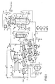
- FIG. 1 there is shown a schematic flow diagram of MR LNG plant 2 which is typical of a plant controlled according to the present invention, and the operation of plant 2 is described in U.S. Patent No. 3,763,658.
- reference numerals used in Fig. 1 correspond to those employed in the figure of the '658 patent.
- MR makeup system 140 includes valves 142a,b,c,d which control the admission of makeup gases to the MR loop. Further description of individual system components will be given as the Detailed Description of the preferred embodiment of the controller warrants.
- LNG production plant 2 is depicted as a region surrounded by a phantom line having inlets for fuel, feed and makeup gases and an outlet for liquified natural gas.
- LNG production facility 2 Within LNG production facility 2 are located a plurality of sensors A-AV and a plurality of controls 200 such as servo-controlled valves such as for controller valve 116. Only valves indicated by an asterisk ( * ) in control column of Table 1 are so controlled; others may be controlled according to prior art manual or automatic controller tech niques.
- Sensors A through AV and controls 200 communicate with process controller 300 through conventional electronic communication means.
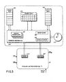
- Process controller 300 comprises sensor memory 330 having individual memory locations corresponding to individual sensors A through AV, controller memory 340 having individual memory locations corresponding to each of controls 200, and a plurality of parallel process loops 320.
- process controller 300 maintains request queue 350 which is a queue of process service requests, and return queue 360.
- Process controller 300 also maintains priority table 370 which is used in order to resolve contention among operating process loops 320. Priorities for Table 370 are listed in Table 2.
- process controller 300 has access to real time clock 310 for measuring intervals and controlling other time sensitive functions.
- the process controller system is implemented in a parallel processing computer system.
- the tasks which are carried out in parallel are low level monitoring and controller functions, system executive management functions, limit and alarm functions necessary to the safe operation of the production plant, and ongoing adjustment functions which provide increases in efficiency independent of the operating state of the production facility.
- Processor controller system 310 allows parallel control processes to be executed on multiple processors having access to a common storage 330 and 340. Within this common storage are stored values representative of the current state of every sensor and every controller associated with production facility 2. In addition, various indicators or flag fields are defined for management of the controller system.
- An active control status indicator is an area of the commonly accessible storage means having one flag significant of each parallel process loop. Upon entry to any loop, the system executive will set the corresponding flag in the active control status indicator. Upon exit from a loop, the system executive clears or resets the corresponding flag. By this mechanism, all parallel processes within the system may determine which processes are currently active and in this way avoid contention or conflict.
- the System Executive (Appendix, page 1) also maintains a request queue 350 and a return queue 360 for management of high priority requests.
- the function of these queues is best described with reference to an example situation within the system:
- the System Executive Upon receiving the activity request from the Antisurge Controller, the System Executive would apply its Resolve Contention routine (Appendix, page 2) in order to determine whether active status should be granted to the Antisurge Control routine.
- the priority of the currently active routine would be compared to the priority assigned to the requesting routine and, assuming the requesting routine has a higher priority level as defined in priority table 370, the loop identification and a reassert timer for the current process would be placed on the System Executive return queue 360.
- the System Executive would then clear the activity status flag of the currently executing loop, set the activity status flag of the Anti-surge Control routine, set a flag indicative of the presence of a record in the return queue, and transfer control to the Antisurge Control routine.
- the System Executive Upon normal exit of the Antisurge Control routine, the System Executive, recognizing its return queue flag, would reactivate the routine which has been executing prior to the occurrence of the surge condition. Alternatively, if the Executive has not reactivated the original process after a specified period of time, the Queue Manager (Appendix, page 2) acts to reassert a request that the process become active again. This reassertion is handled by the Resolve Contention process within the System Executive which will either allow reactivation, or will again defer the process by placing it on the request queue.
- the identification of that requesting process is placed on a request queue along with a reassertion timer.
- the request queue 350 also has a corresponding flag within the System Executive. Should a process terminate, the System Executive will verify the status of those routines which have been placed within the system request queue and will attempt to execute these by reasserting the request through the Resolve Contention process. In this way, the process controller of the present invention is assured that it will spend no idle time unless there is only a single routine executing and no other processes are requesting service.
- the architecture described above may be approximated by a sequential process.
- a sequential process must be event or interrupt driven and the time necessary to execute the major control loop must be short enough so as not to unduly damp the response of controller 300.
- Table 1 there is shown a cross-reference table indicating the component descriptions of the major components depicted in Figs. 1 and 2, the locations of various sensors within production system 2, and the variables represented by both sensors and controllers which are used in the control program shown in pseudocode listing Appendix.
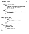
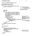
- the System Executive routine comprises a parallel processing loop for executing System Executive management functions, low lever alarm operation functions, ongoing monitoring functions, and controller functions. These functions are depicted as operating procedures which execute in parallel. This architecture is one in which each executing process may occupy its own unique processor in the parallel processing system. It will be understood that parallel processes may be executed on one or a plurality of processors. Division of labour will necessarily depend upon the availability of processors for a particular implementation.
- the Monitor Operating Parameters routine actually executes as 43 concurrent processes, each associated with a particular sensor within system 2.
- Each parallel routine is a programmatic loop which fetches the sensor value and places that value in a predefined memory location. It will be understood that such a routine may also include filtering and scaling steps unique to a particular sensor or group of sensors. For instance, where a sensor is subject to high levels of noise, band-pass filtering or time weighted integration may be applied in order to reduce the noise level. Alternatively, raw sensor data may be placed in memory where it is subsequently processed for noise filtering, scaling, or other such requirements.
- the Set Controllers routine similarly comprises 17 parallel routines, each corresponding to a given controller within system 2.
- the Set Controllers routine may also employ signal processing techniques for adjusting for variances in gain, response time, and providing damping of controllers.
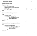
- the Resolve Contention routine references priority table 370.
- Example values contained in priority table 370 are included in Table 2. These priority values may change based upon a particular system configuration and are intended as an example of the contention resolution function.
- Monitor Production is the main routine which operates in parallel with the lower level alarm, monitor and controller functions to allow optimization of the production system. It is the Monitor Production routine which determines the current production rate of the entire system and calls subsidiary routines in accordance with the variance of that rate from the desired or target production. It is anticipated that the largest percentage of the time, Monitor Production routine will call the Optimize routine. However, when actual production either falls below or rises above the operator specified target production, then routines Turn Down Production or Turn Up Production are called.
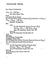
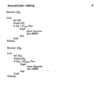
- Routine Optimize begins by ascertaining whether the correct inventory level of MR liquid is present in high pressure MR separator 110. The correct level of MR liquid is specified as being below the level of level sensor T and above the level of level sensor U. Should the MR liquid inventory be found to be below the lower limit, then routine MR Liquid Level Makeup Composition and Flow will be executed. This routine will be described below. In the event that the MR liquid level is above the upper bound, MR liquid drain valve 115 is opened in order to drain high pressure separator 110. Drain valve 115 is left open until the level within high pressure separator 110 falls below that of sensor U.
- the MR composition is then optimized.
- the roughest optimization of MR composition involves adjustment of flow ratio controller (FRC) valve 116. Such an optimization is carried out with regard to the overall efficiency of production facility 2.
- FRC flow ratio controller
- Pseudocode Function Efficiency is used in the calculation of overall system operational efficiency. This calculation involves the total energy consumed by the system and the economic value of the liquified natural gas produced. For example, for a given fuel flow, at a particular fuel composition, a fuel heating value is obtained. Such a heating value is typically obtained through a two-step process in volving chromatographic analysis of the fuel in order to determine its composition and a multiplication process of each fuel component by its heating value. The heating value is typically obtained from tables published by the Gas Processing and Suppliers Association for each hydrocarbon component of a typical gas stream. By multiplying fuel heating value by flow, a total energy consumption for the system is available.
- the calculated energy consumption is then divided by the value of liquified natural gas produced using the energy.
- the value of each cubic foot would be divided into the energy consumed for its production in order to give an instantaneous efficiency figure expressed in terms of energy per dollar profit.
- This instantaneous efficiency may be stored and compared to later readings of efficiency in order to provide a comparison for a particular optimization of adjustment.
- the setting of the flow ratio controller valve 116, nitrogen content of the MR, and C 3 :C 2 ratio is done sequentially by an algorithm which attempts to find peak efficiency while adjusting the given parameter.
- the compression ratio controller (CRC) valve 128 is adjusted for peak efficiency.
- the compression ratio is incremented by a percentage which is determined by experience. This percentage would be initially input from the design specifications for the facility but would subsequently be adjusted within the controller program itself to provide an optimum step value.
- the optimization of compression ratio begins by incrementing the compression ratio until a peak efficiency is reached or until the MR compressor discharge pressure exceeds a predefined maximum pressure. When either of these conditions is met, the compression ratio is decremented until the efficiency falls. After finding maximum efficiency versus compression ratio, the last optimization step performed is an optimization of compressor turbine speed.
- the optimization begins by ascertaining whether current speed is maximal (with regard to design ratings). If current speed is - not maximal, the speed is incremented until an optimum efficiency is found or maximum speed is achieved.
- the Monitor Production routine is again iterated. In most instances, optimization will have increased production so that it will be possible to decrease production to the predetermined target level, thus conserving input energy. This permits the facility to run at maximum efficiency while maintaining a predetermined level of production.
- Routine Turn Down Production (Appendix, page 4) is called when the Monitor Production routine determines that measured production of the system exceeds the operator input target production.
- the Turn Down Production routine first determines whether the measured production is within 4% of desired target production. If measured production falls within this range, then the routine branches to the Turn Down Fine label for a fine adjustment of the production rate. If measured production exceeds target production plus 4%, execution at label Turn Down Gross first ascertains the MR compressor suction pressure and stores this value in memory. If it is determined that the MR compressor suction pressure is less than the minimum allowable pressure plus 4%, then no adjustment is made and operation returns to the Monitor Production routine. If, however, the MR compressor suction pressure is above this threshold, then MR compressor suction vent 151 is opened to allow the MR compressor suction pressure to fall by 4%.
- the Optimize routine is called in order to re-optimize the system and then the main routine Monitor Production is again called.
- the compressor suction pressure is reduced by opening of MR compressor suction vent 151. This reduction is accomplished accor ding to a ratio including the difference between measured production and target production. In this way, a gradual intercept to target production can be made without upsetting the plant.
- the system is re-optimized and the main loop is re-executed.
- the routine Turn Up Production (Appendix, page 5) is called by the Monitor Production routine.
- the Turn Up Production routine first determines whether measured production exceeds target production minus 4%. If measured production falls below this level, execution continues at label Turn Up Gross.
- a predetermined amount of nitrogen is injected by opening valve 142a.
- the routine then waits for a predetermined amount of time and repeats the process until the cold end AT falls outside the acceptable limits. Once it is determined that the cold end AT is sufficiently large, then a target MR compressor suction pressure is calculated as the current pressure plus 4%.
- the C Inject routine is then executed, followed by the monitor production main loop.
- Turn Up Fine When it is determined that a fine upward adjustment of production is required, the routine Turn Up Fine is called. Turn Up Fine first optimizes the system and then ascertains whether measured production is still below target production. If measured production remains below target production, then a new target MR compressor suction pressure is calculated as a ratio between the target and measured productions and the C Inject routine is called.
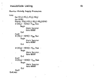
- the routine MR Liquid Level Makeup Composition and Flow (Appendix, page 6), which is called by the Optimize routine when it is determined that mixed refrigerant liquid inventory is low, there is shown a preferred embodiment for the liquid level makeup function.
- the routine begins by storing in memory the initial makeup inlet valve positions. These valves are positioned by other routines in order to compensate for leakages in the facility. At steady state operation, each valve's flow rate will precisely balance the leakage of its particular component from the system. The routine then proceeds to a loop in which it ascertains the molar composition of each of the components of the mixed refrigerant. The inventory to be made up is then calculated.
- This inventory makeup rate includes an estimated time during which the inventory should be brought to within acceptable limits.
- a timer is reset and started and the makeup valves 142a,b,c,d are pro portionally opened to a degree represented by the product of the molar faction of the particular component being injected and the overall makeup rate which is calculated.
- the MR makeup flow is ascertained and the time estimate used for calculating flow rate is decreased by the amount of elapsed time. A new makeup flow rate is then calculated.
- the time estimate is decremented by a predetermined amount and a new makeup flow rate is calculated in order to increase makeup rate. If it is determined that the total flow rate required by the new makeup rate divided by the remaining time is greater than the maximum flow rate achievable, then an operator alarm is sounded and the controller loop is aborted. The abort procedure discontinues the parallel processing loop and begins the sequential procedure abort within the System Executive. At the conclusion of the makeup loop, the initial makeup inlet valve positions are restored in order to again balance leakage from the system.
- the C Inject routine (Appendix, page 8) is called by the Turn Up Production routine. It begins by opening the C 1 injection valve 142b. A series of tests are then performed for certain physical limits of the system. The compressor discharge pressure is measured in order to assure that it remains below a design maximum, and the warm and cold end upset A Ps are measured to ascertain that the remain within design limits. Finally, the turbine firing temperatures are measured. If all of these critical parameters are within design specification limits, the MR compressor suction pressure is measured. When this pressure reaches the target compressor suction pressure, then C 1 injection valve 142b is closed and the Optimize routine is called. If any of the design specifications are exceeded, the C 1 injection valve 142b is closed immediately and, if the flag OPT is set, the production target is rest downward. If the flag OPT is not set, then the Optimize routine is called after setting OPT.
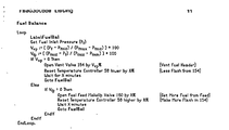
- the ongoing Fuel Balance routine maintains the fuel header pressure at the fuel header pressure midpoint.
- the routine calculates the distance from the pressure midpoint by means_of distance algorithms employing the fuel inlet pressure as well as the design maximum, midpoint and minimum pressures for the fuel header.
- vent valve 164 is opened proportionally in order to reduce the fuel header pressure.
- temperature controller 58 is reset to a lower temperature by a predetermined percentage in order to reduce the amount of fuel derived from a flash in receiver 154.
- fuel feed makeup valve 160 is opened by a predetermined amount and temperature controller 58 is reset higher by a predetermined percentage in order to produce more flash in receiver 154.
- the Compressor Turbine Overspeed Control routine (Appendix page 7) is a concurrently operating process which continually compares compressor turbine speed to the design maximum speed for the machine. Should turbine speed exceed design maximum, an alarm will be set and speed will immediately be reduced to, for example, 105% of design.
- the Compressor Turbine Overtemperature Control (Appendix, page 7) continuously monitors compressor turbine firing temperature and compares that temperature to the design maximum temperature. Should turbine temperature exceed the design maximum, the turbine overtemperature alarm is set and the fuel being fed to the turbine is reduced by a predetermined percentage in order to reduce the firing temperature.
- the automatic controller When the Abort procedure is initiated, the automatic controller is taken off-line to prevent it from continuing to operate the system and manual control from the operator is accepted. In an effort to continue to assist the operator, several parallel processes are restarted once manual control has begun. These processes include Monitor Operating Parameters, Antisurge Control, Turbine Overspeed and Overtemperature Control, and Fuel Balance. These routines continue to operate until the human operator of the system has resolved the emergency situation causing the abort and manually restarts the process control system, which then reinitializes the system and recommences the parallel processing loop of the System Executive.
- the preferred embodiment of the present invention is programmed to operate in a parallel processing computer system.
- a parallel processing computer system comprises a plurality of IMS T414 transputers from Inmos Corporation.
- Other alternative embodiments include various parallel processing systems and architectures including, for example, Hypercube computers such as those produced by Ametek, Inc.
- a sufficiently fast sequential processor may be programmed to provide interrupt or event driven service to time critical routines.
- a dedicated interrupt priority controller would be used in order to assure interrupt service to those critical routines.
- a main loop which performs the functions of the routines Monitor Operating Parameters, Set Controllers, Monitor Production, Fuel Balance, and the other routines executed in parallel according to the pseudocode listing could be programmed.
- interrupt controller includes the provision of seven levels of interrupt priority as follows: Antisurge Control, Compressor Turbine Overspeed Control, Compressor Turbine Overtemperature Control, Sense Feed Pressure, Monitor AT c , Monitor ⁇ T w , Monitor Makeup Supply Pressure.
- System 2 uses two analyzers for providing on-stream analysis of the mixed refrigerant composition and the fuel compositions.
- a typical analyzer is a Bendix Chromatograph Model 002-833 fitted with a flame ionization detector.
- Typical MR compositions are:
- Typical compositions for a natural gas feed are as follows:
- a heating value is calculated according to the values published in the Gas Processors Suppliers Association Engineering Data Book (Section 16). This table lists both net heating value and gross heating value. Gross heating value is defined as net heating value plus the latent heat of water and is the value used in calculating the overall heating value for a particular fuel composition. Fuel heating value is defined as the heating value of a particular component of the fuel times the molar fraction of that component in the fuel. The sum of these products constitutes the fuel heating value.
- the present invention is applicable to the control of mixed refrigerant-type liquified natural gas production facilities in order to provide more efficient operation of those facilities.
Landscapes
- Engineering & Computer Science (AREA)
- Physics & Mathematics (AREA)
- Mechanical Engineering (AREA)
- Thermal Sciences (AREA)
- General Engineering & Computer Science (AREA)
- Chemical & Material Sciences (AREA)
- Oil, Petroleum & Natural Gas (AREA)
- Combustion & Propulsion (AREA)
- Chemical Kinetics & Catalysis (AREA)
- General Chemical & Material Sciences (AREA)
- Separation By Low-Temperature Treatments (AREA)
- Feedback Control In General (AREA)
Applications Claiming Priority (2)
| Application Number | Priority Date | Filing Date | Title |
|---|---|---|---|
| US884122 | 1986-07-10 | ||
| US06/884,122 US4809154A (en) | 1986-07-10 | 1986-07-10 | Automated control system for a multicomponent refrigeration system |
Publications (3)
| Publication Number | Publication Date |
|---|---|
| EP0252455A2 true EP0252455A2 (fr) | 1988-01-13 |
| EP0252455A3 EP0252455A3 (en) | 1988-09-14 |
| EP0252455B1 EP0252455B1 (fr) | 1993-03-31 |
Family
ID=25384000
Family Applications (1)
| Application Number | Title | Priority Date | Filing Date |
|---|---|---|---|
| EP87109630A Expired - Lifetime EP0252455B1 (fr) | 1986-07-10 | 1987-07-03 | Régulation d'un système de refroidissement à composant multiples pour la liquéfaction de gaz naturel |
Country Status (9)
| Country | Link |
|---|---|
| US (1) | US4809154A (fr) |
| EP (1) | EP0252455B1 (fr) |
| JP (1) | JP2599919B2 (fr) |
| KR (1) | KR940001381B1 (fr) |
| AU (1) | AU595627B2 (fr) |
| CA (1) | CA1325255C (fr) |
| DE (1) | DE3785098T2 (fr) |
| MY (1) | MY100386A (fr) |
| NO (1) | NO168443C (fr) |
Cited By (6)
| Publication number | Priority date | Publication date | Assignee | Title |
|---|---|---|---|---|
| WO1999031448A1 (fr) * | 1997-12-12 | 1999-06-24 | Shell Internationale Research Maatschappij B.V. | Procede de liquefaction d'une alimentation gazeuse riche en methane pour obtenir du gaz naturel liquefie |
| US7266975B2 (en) | 2003-01-31 | 2007-09-11 | Shell Oil Company | Process of Liquefying a gaseous, methane-rich feed to obtain liquefied natural gas |
| WO2008157102A2 (fr) * | 2007-06-12 | 2008-12-24 | Honeywell International Inc. | Appareil et procédé d'optimisation d'un train de liquéfaction de gaz naturel présentant une boucle de refroidissement à l'azote |
| US20160102908A1 (en) * | 2014-10-10 | 2016-04-14 | Air Products And Chemicals, Inc. | Refrigerant Recovery in Natural Gas Liquefaction Processes |
| US20180128543A1 (en) * | 2016-11-10 | 2018-05-10 | Woodside Energy Technologies Pty Ltd | Method and controller for controlling a continuous process |
| EP3368630B1 (fr) | 2015-10-27 | 2020-12-02 | Linde GmbH | Réfrigérant mélangé basse température pour pré-refroidissement d'hydrogène à grande échelle |
Families Citing this family (57)
| Publication number | Priority date | Publication date | Assignee | Title |
|---|---|---|---|---|
| US4878002A (en) * | 1988-10-27 | 1989-10-31 | Advanced Engineering Systems, Operations & Products, Inc. | Multi-axis DSP-based parallel processing servo controller for machine tools and robots |
| US4970867A (en) * | 1989-08-21 | 1990-11-20 | Air Products And Chemicals, Inc. | Liquefaction of natural gas using process-loaded expanders |
| US5060133A (en) * | 1990-02-06 | 1991-10-22 | Automation Intelligence, Inc. | Transputer CNC processor |
| GB9103622D0 (en) * | 1991-02-21 | 1991-04-10 | Ugland Eng | Unprocessed petroleum gas transport |
| US5139548A (en) * | 1991-07-31 | 1992-08-18 | Air Products And Chemicals, Inc. | Gas liquefaction process control system |
| US5287703A (en) * | 1991-08-16 | 1994-02-22 | Air Products And Chemicals, Inc. | Process for the recovery of C2 + or C3 + hydrocarbons |
| FR2703762B1 (fr) * | 1993-04-09 | 1995-05-24 | Maurice Grenier | Procédé et installation de refroidissement d'un fluide, notamment pour la liquéfaction de gaz naturel. |
| US5486995A (en) * | 1994-03-17 | 1996-01-23 | Dow Benelux N.V. | System for real time optimization |
| ATE199188T1 (de) * | 1994-03-17 | 2001-02-15 | Dow Benelux | System zur echtzeit optimierung und darstellung des gewinns |
| US5791160A (en) * | 1997-07-24 | 1998-08-11 | Air Products And Chemicals, Inc. | Method and apparatus for regulatory control of production and temperature in a mixed refrigerant liquefied natural gas facility |
| US6119479A (en) | 1998-12-09 | 2000-09-19 | Air Products And Chemicals, Inc. | Dual mixed refrigerant cycle for gas liquefaction |
| JP2000346472A (ja) * | 1999-06-08 | 2000-12-15 | Mitsubishi Heavy Ind Ltd | 超臨界蒸気圧縮サイクル |
| US6876991B1 (en) | 1999-11-08 | 2005-04-05 | Collaborative Decision Platforms, Llc. | System, method and computer program product for a collaborative decision platform |
| EG23193A (en) * | 2000-04-25 | 2001-07-31 | Shell Int Research | Controlling the production of a liquefied natural gas product stream. |
| US6553772B1 (en) | 2002-05-09 | 2003-04-29 | Praxair Technology, Inc. | Apparatus for controlling the operation of a cryogenic liquefier |
| US6662589B1 (en) | 2003-04-16 | 2003-12-16 | Air Products And Chemicals, Inc. | Integrated high pressure NGL recovery in the production of liquefied natural gas |
| US7500370B2 (en) * | 2006-03-31 | 2009-03-10 | Honeywell International Inc. | System and method for coordination and optimization of liquefied natural gas (LNG) processes |
| WO2007123924A2 (fr) * | 2006-04-19 | 2007-11-01 | Saudi Arabian Oil Company | Optimisation d'une installation à liquides de gaz naturel à système de réfrigération double |
| US20080016910A1 (en) * | 2006-07-21 | 2008-01-24 | Adam Adrian Brostow | Integrated NGL recovery in the production of liquefied natural gas |
| AU2007286291B2 (en) * | 2006-08-14 | 2010-08-12 | Shell Internationale Research Maatschappij B.V. | Method and apparatus for cooling a hydrocarbon stream |
| JP2008057893A (ja) * | 2006-08-31 | 2008-03-13 | Sanyo Electric Co Ltd | 空気調和システム及び空気調和システムの制御装置 |
| US7712299B2 (en) * | 2006-09-05 | 2010-05-11 | Conocophillips Company | Anti-bogdown control system for turbine/compressor systems |
| KR100844324B1 (ko) * | 2007-01-26 | 2008-07-07 | 엘지전자 주식회사 | 멀티에어컨의 디맨드 제어시스템 및 디맨드 제어방법 |
| GB0706554D0 (en) * | 2007-04-03 | 2007-05-09 | Rolls Royce Plc | Analysis method |
| JP5683266B2 (ja) * | 2007-07-12 | 2015-03-11 | シエル・インターナシヨネイル・リサーチ・マーチヤツピイ・ベー・ウイShell Internationale Research Maatschappij Beslotenvennootshap | 炭化水素流の冷却方法及び装置 |
| US20090025422A1 (en) | 2007-07-25 | 2009-01-29 | Air Products And Chemicals, Inc. | Controlling Liquefaction of Natural Gas |
| WO2009029420A1 (fr) * | 2007-08-27 | 2009-03-05 | Johnson Controls Technology Company | Procédé de commande pour la compression de gaz |
| US20090149996A1 (en) * | 2007-12-05 | 2009-06-11 | Applied Materials, Inc. | Multiple inlet abatement system |
| RU2495343C2 (ru) * | 2008-02-08 | 2013-10-10 | Шелл Интернэшнл Рисерч Маатсхаппий Б.В. | Способ и устройство для охлаждения криогенного теплообменника и способ сжижения углеводородного потока |
| KR100929095B1 (ko) * | 2008-04-07 | 2009-11-30 | 현대중공업 주식회사 | 연료가스 공급과 액화 천연가스 생산이 동시에 가능한 액화천연가스 생산 장치 |
| KR101606364B1 (ko) * | 2008-07-29 | 2016-03-25 | 쉘 인터내셔날 리써취 마트샤피지 비.브이. | 압축기를 제어하기 위한 방법 및 장치 및 탄화수소 스트림을 냉각시키는 방법 |
| US20110168377A1 (en) * | 2008-09-19 | 2011-07-14 | Paul Theo Alers | Method of cooling a hydrocarbon stream and an apparatus therefor |
| CN102365518B (zh) * | 2008-12-09 | 2014-06-18 | 国际壳牌研究有限公司 | 操作压缩机的方法及其设备 |
| US8352152B2 (en) * | 2009-02-10 | 2013-01-08 | Honeywell International Inc. | System, method, apparatus and computer program product for providing improved engine control |
| US20120060552A1 (en) * | 2009-05-18 | 2012-03-15 | Carolus Antonius Cornelis Van De Lisdonk | Method and apparatus for cooling a gaseous hydrocarbon stream |
| WO2010133482A2 (fr) * | 2009-05-18 | 2010-11-25 | Shell Internationale Research Maatschappij B.V. | Procédé et appareil de refroidissement d'un flux d'hydrocarbures gazeux |
| WO2011009832A2 (fr) * | 2009-07-21 | 2011-01-27 | Shell Internationale Research Maatschappij B.V. | Procédé pour le traitement d'un courant d'hydrocarbure à plusieurs phases et appareil correspondant |
| WO2011120096A1 (fr) * | 2010-03-31 | 2011-10-06 | Woodside Energy Limited | Échangeur de chaleur principal et procédé pour refroidir un courant latéral de tubes |
| CN103250169A (zh) * | 2010-09-03 | 2013-08-14 | Abb研究有限公司 | 用于通过优化的能量基准测试和诊断的方法及其系统 |
| MY163848A (en) * | 2011-03-15 | 2017-10-31 | Petroliam Nasional Berhad (Petronas) | A method and system for controlling the temperature of liquefied natural gas in a liquefaction process |
| CN102628634B (zh) * | 2012-04-26 | 2013-10-30 | 中国石油集团工程设计有限责任公司 | 三循环复叠式制冷天然气液化系统及方法 |
| EP3032204A1 (fr) | 2014-12-11 | 2016-06-15 | Shell Internationale Research Maatschappij B.V. | Procédé et système de production d'un flux d'hydrocarbures refroidis |
| CN107405602B (zh) | 2015-03-05 | 2020-08-21 | 国际壳牌研究有限公司 | 甲烷氧化催化剂、其制备方法及其使用方法 |
| CA2997617C (fr) | 2015-10-06 | 2020-10-27 | Halliburton Energy Services, Inc. | Systeme d'optimisation de gaz dynamique |
| WO2017154181A1 (fr) * | 2016-03-10 | 2017-09-14 | 日揮株式会社 | Procédé de détermination de composition de fluide frigorigène mixte pour dispositif de liquéfaction de gaz naturel |
| US10393429B2 (en) | 2016-04-06 | 2019-08-27 | Air Products And Chemicals, Inc. | Method of operating natural gas liquefaction facility |
| WO2018019749A1 (fr) | 2016-07-26 | 2018-02-01 | Shell Internationale Research Maatschappij B.V. | Procédé et appareil pour le refroidissement d'un échangeur de chaleur cryogénique |
| BR112019004036B1 (pt) | 2016-08-31 | 2022-11-29 | Shell Internationale Research Maatschappij B.V. | Processo para preparar um catalisador de oxidação de metano e método de oxidação de metano |
| JP7015298B2 (ja) | 2016-08-31 | 2022-02-15 | シエル・インターナシヨネイル・リサーチ・マーチヤツピイ・ベー・ウイ | メタン酸化触媒、それを調製するプロセス、およびそれを使用する方法 |
| US10584918B2 (en) * | 2017-01-24 | 2020-03-10 | GE Oil & Gas, LLC | Continuous mixed refrigerant optimization system for the production of liquefied natural gas (LNG) |
| RU2640976C1 (ru) | 2017-05-05 | 2018-01-12 | Компания "Сахалин Энерджи Инвестмент Компани Лтд." | Способ управления процессом сжижения природного газа |
| US10753677B2 (en) * | 2017-06-08 | 2020-08-25 | General Electric Company | Methods and systems for enhancing production of liquefied natural gas |
| WO2019017421A1 (fr) * | 2017-07-19 | 2019-01-24 | 千代田化工建設株式会社 | Système de prédiction de sortie de production de gnl |
| JP7116392B2 (ja) * | 2019-07-10 | 2022-08-10 | 日揮グローバル株式会社 | 天然ガスプラントの稼働解析方法 |
| US20220333857A1 (en) * | 2020-05-27 | 2022-10-20 | Chiyoda Corporation | Method and system for determining operating conditions of liquefied natural gas plant |
| US20220099364A1 (en) * | 2020-09-29 | 2022-03-31 | L'Air Liquide, Société Anonyme pour l'Etude et I'Exploitation des Procédés Georges Claude | Offshore liquefaction process without compression |
| CN114674112A (zh) * | 2022-04-07 | 2022-06-28 | 安阳钢铁股份有限公司 | 一种液化装置氧氮自动转换方法 |
Citations (3)
| Publication number | Priority date | Publication date | Assignee | Title |
|---|---|---|---|---|
| FR2074594A1 (fr) * | 1970-01-08 | 1971-10-08 | Technip Cie | |
| US3763658A (en) * | 1970-01-12 | 1973-10-09 | Air Prod & Chem | Combined cascade and multicomponent refrigeration system and method |
| FR2590494A1 (fr) * | 1985-11-22 | 1987-05-29 | Hitachi Ltd | Procede de commande d'un separateur d'air |
Family Cites Families (6)
| Publication number | Priority date | Publication date | Assignee | Title |
|---|---|---|---|---|
| US29914A (en) * | 1860-09-04 | Portable india-rubber bathing-tub | ||
| US3364685A (en) | 1965-03-31 | 1968-01-23 | Cie Francaise D Etudes Et De C | Method and apparatus for the cooling and low temperature liquefaction of gaseous mixtures |
| US4033735A (en) * | 1971-01-14 | 1977-07-05 | J. F. Pritchard And Company | Single mixed refrigerant, closed loop process for liquefying natural gas |
| AU8274282A (en) * | 1981-03-16 | 1982-10-06 | Cantley, Robert J. | Energy management system for refrigeration systems |
| US4584006A (en) * | 1982-03-10 | 1986-04-22 | Flexivol, Inc. | Process for recovering propane and heavier hydrocarbons from a natural gas stream |
| US4504296A (en) * | 1983-07-18 | 1985-03-12 | Air Products And Chemicals, Inc. | Double mixed refrigerant liquefaction process for natural gas |
-
1986
- 1986-07-10 US US06/884,122 patent/US4809154A/en not_active Expired - Fee Related
-
1987
- 1987-07-03 DE DE8787109630T patent/DE3785098T2/de not_active Expired - Fee Related
- 1987-07-03 AU AU75223/87A patent/AU595627B2/en not_active Ceased
- 1987-07-03 CA CA000541188A patent/CA1325255C/fr not_active Expired - Fee Related
- 1987-07-03 EP EP87109630A patent/EP0252455B1/fr not_active Expired - Lifetime
- 1987-07-04 MY MYPI87000945A patent/MY100386A/en unknown
- 1987-07-08 KR KR1019870007285A patent/KR940001381B1/ko not_active IP Right Cessation
- 1987-07-09 JP JP62169917A patent/JP2599919B2/ja not_active Expired - Lifetime
- 1987-07-09 NO NO872867A patent/NO168443C/no unknown
Patent Citations (3)
| Publication number | Priority date | Publication date | Assignee | Title |
|---|---|---|---|---|
| FR2074594A1 (fr) * | 1970-01-08 | 1971-10-08 | Technip Cie | |
| US3763658A (en) * | 1970-01-12 | 1973-10-09 | Air Prod & Chem | Combined cascade and multicomponent refrigeration system and method |
| FR2590494A1 (fr) * | 1985-11-22 | 1987-05-29 | Hitachi Ltd | Procede de commande d'un separateur d'air |
Non-Patent Citations (1)
| Title |
|---|
| Chatterjee et al, "Operational Flexibility of LNG Plants using the Propane Precooled Multicomponent Refrigerant MCR Process", 5th International Conference on Liquefied Natural Gas, 1977 * |
Cited By (12)
| Publication number | Priority date | Publication date | Assignee | Title |
|---|---|---|---|---|
| WO1999031448A1 (fr) * | 1997-12-12 | 1999-06-24 | Shell Internationale Research Maatschappij B.V. | Procede de liquefaction d'une alimentation gazeuse riche en methane pour obtenir du gaz naturel liquefie |
| AU732548B2 (en) * | 1997-12-12 | 2001-04-26 | Shell Internationale Research Maatschappij B.V. | Process of liquefying a gaseous, methane-rich feed to obtain liquefied natural gas |
| US6272882B1 (en) | 1997-12-12 | 2001-08-14 | Shell Research Limited | Process of liquefying a gaseous, methane-rich feed to obtain liquefied natural gas |
| US7266975B2 (en) | 2003-01-31 | 2007-09-11 | Shell Oil Company | Process of Liquefying a gaseous, methane-rich feed to obtain liquefied natural gas |
| WO2008157102A2 (fr) * | 2007-06-12 | 2008-12-24 | Honeywell International Inc. | Appareil et procédé d'optimisation d'un train de liquéfaction de gaz naturel présentant une boucle de refroidissement à l'azote |
| WO2008157102A3 (fr) * | 2007-06-12 | 2012-04-12 | Honeywell International Inc. | Appareil et procédé d'optimisation d'un train de liquéfaction de gaz naturel présentant une boucle de refroidissement à l'azote |
| US8783061B2 (en) | 2007-06-12 | 2014-07-22 | Honeywell International Inc. | Apparatus and method for optimizing a natural gas liquefaction train having a nitrogen cooling loop |
| US20160102908A1 (en) * | 2014-10-10 | 2016-04-14 | Air Products And Chemicals, Inc. | Refrigerant Recovery in Natural Gas Liquefaction Processes |
| US9759480B2 (en) * | 2014-10-10 | 2017-09-12 | Air Products And Chemicals, Inc. | Refrigerant recovery in natural gas liquefaction processes |
| US10788260B2 (en) | 2014-10-10 | 2020-09-29 | Air Products And Chemicals, Inc. | Refrigerant recovery in natural gas liquefaction processes |
| EP3368630B1 (fr) | 2015-10-27 | 2020-12-02 | Linde GmbH | Réfrigérant mélangé basse température pour pré-refroidissement d'hydrogène à grande échelle |
| US20180128543A1 (en) * | 2016-11-10 | 2018-05-10 | Woodside Energy Technologies Pty Ltd | Method and controller for controlling a continuous process |
Also Published As
| Publication number | Publication date |
|---|---|
| KR880001992A (ko) | 1988-04-28 |
| KR940001381B1 (ko) | 1994-02-21 |
| DE3785098D1 (de) | 1993-05-06 |
| NO872867L (no) | 1988-01-11 |
| AU7522387A (en) | 1988-01-14 |
| JPS6325481A (ja) | 1988-02-02 |
| NO168443B (no) | 1991-11-11 |
| EP0252455B1 (fr) | 1993-03-31 |
| US4809154A (en) | 1989-02-28 |
| MY100386A (en) | 1990-09-17 |
| DE3785098T2 (de) | 1993-07-08 |
| CA1325255C (fr) | 1993-12-14 |
| AU595627B2 (en) | 1990-04-05 |
| EP0252455A3 (en) | 1988-09-14 |
| NO168443C (no) | 1992-02-19 |
| JP2599919B2 (ja) | 1997-04-16 |
| NO872867D0 (no) | 1987-07-09 |
Similar Documents
| Publication | Publication Date | Title |
|---|---|---|
| EP0252455A2 (fr) | Régulation d'un système de refroidissement à composant multiples pour la liquéfaction de gaz naturel | |
| US6711911B1 (en) | Expansion valve control | |
| AU2017202136B2 (en) | Method of operating natural gas liquefaction facility | |
| CN109855251B (zh) | 空调的排气过热度修正方法、装置、计算机产品及空调 | |
| Schmal et al. | Internal versus external heat integration: operational and economic analysis | |
| US20200018523A1 (en) | Refrigerating system and refrigerating system control method | |
| US5677677A (en) | System for monitoring the operation of an evaporator unit | |
| Shin et al. | Dynamic matrix control applied on propane-mixed refrigerant liquefaction process | |
| CN113357803B (zh) | 用于控制空调器电子膨胀阀的方法及装置、空调器 | |
| CN114413497A (zh) | 双级压缩机及控制方法、装置以及控制设备、制冷设备 | |
| CN112665245B (zh) | 冷水机组的负荷调节控制方法、装置及冷水机组 | |
| CN111397176B (zh) | 一种高温制冷控制方法、装置及空调设备 | |
| CN107636553B (zh) | 用于控制模型预测控制器中的斜坡失衡的系统和方法 | |
| CN112161390A (zh) | 电子膨胀阀控制方法、装置和空调 | |
| CN114992927B (zh) | 一种压缩机喷液控制方法、装置及机组 | |
| CN114992805B (zh) | 空调器性能匹配方法、装置、电子设备及空调 | |
| CN111306695A (zh) | 压缩机负载数据优化方法、装置、计算机设备和存储介质 | |
| CN110094864A (zh) | 一种温度传感器的自动选择方法、装置及空调设备 | |
| Al Dhaheri et al. | Modifying Control Logic to Improve Plant Availability | |
| US20220390170A1 (en) | Optimized natural gas production control system with actual flow and set point tracking features | |
| WO2021103542A1 (fr) | Procédé et système de détermination de fréquence de démarrage de climatiseur | |
| Wong et al. | Multiple liquid chillers: Intelligent control | |
| JPH0633871B2 (ja) | 低温液化ガス貯槽の内圧制御方法 | |
| Niu | Overall Control Strategy | |
| CN110032060A (zh) | 过程控制方法、过程控制装置和存储介质 |
Legal Events
| Date | Code | Title | Description |
|---|---|---|---|
| PUAI | Public reference made under article 153(3) epc to a published international application that has entered the european phase |
Free format text: ORIGINAL CODE: 0009012 |
|
| AK | Designated contracting states |
Kind code of ref document: A2 Designated state(s): BE DE FR GB IT NL |
|
| PUAL | Search report despatched |
Free format text: ORIGINAL CODE: 0009013 |
|
| AK | Designated contracting states |
Kind code of ref document: A3 Designated state(s): BE DE FR GB IT NL |
|
| 17P | Request for examination filed |
Effective date: 19890224 |
|
| 17Q | First examination report despatched |
Effective date: 19890918 |
|
| ITTA | It: last paid annual fee | ||
| GRAA | (expected) grant |
Free format text: ORIGINAL CODE: 0009210 |
|
| AK | Designated contracting states |
Kind code of ref document: B1 Designated state(s): BE DE FR GB IT NL |
|
| REF | Corresponds to: |
Ref document number: 3785098 Country of ref document: DE Date of ref document: 19930506 |
|
| ET | Fr: translation filed | ||
| ITF | It: translation for a ep patent filed |
Owner name: DR. ING. A. RACHELI & C. |
|
| PLBE | No opposition filed within time limit |
Free format text: ORIGINAL CODE: 0009261 |
|
| STAA | Information on the status of an ep patent application or granted ep patent |
Free format text: STATUS: NO OPPOSITION FILED WITHIN TIME LIMIT |
|
| 26N | No opposition filed | ||
| PGFP | Annual fee paid to national office [announced via postgrant information from national office to epo] |
Ref country code: GB Payment date: 19970620 Year of fee payment: 11 |
|
| PGFP | Annual fee paid to national office [announced via postgrant information from national office to epo] |
Ref country code: NL Payment date: 19970625 Year of fee payment: 11 |
|
| PGFP | Annual fee paid to national office [announced via postgrant information from national office to epo] |
Ref country code: FR Payment date: 19970711 Year of fee payment: 11 |
|
| PGFP | Annual fee paid to national office [announced via postgrant information from national office to epo] |
Ref country code: DE Payment date: 19970729 Year of fee payment: 11 |
|
| PGFP | Annual fee paid to national office [announced via postgrant information from national office to epo] |
Ref country code: BE Payment date: 19970808 Year of fee payment: 11 |
|
| PG25 | Lapsed in a contracting state [announced via postgrant information from national office to epo] |
Ref country code: GB Free format text: LAPSE BECAUSE OF NON-PAYMENT OF DUE FEES Effective date: 19980703 |
|
| PG25 | Lapsed in a contracting state [announced via postgrant information from national office to epo] |
Ref country code: BE Free format text: LAPSE BECAUSE OF NON-PAYMENT OF DUE FEES Effective date: 19980731 |
|
| BERE | Be: lapsed |
Owner name: AIR PRODUCTS AND CHEMICALS INC. Effective date: 19980731 |
|
| PG25 | Lapsed in a contracting state [announced via postgrant information from national office to epo] |
Ref country code: NL Free format text: LAPSE BECAUSE OF NON-PAYMENT OF DUE FEES Effective date: 19990201 |
|
| GBPC | Gb: european patent ceased through non-payment of renewal fee |
Effective date: 19980703 |
|
| PG25 | Lapsed in a contracting state [announced via postgrant information from national office to epo] |
Ref country code: FR Free format text: LAPSE BECAUSE OF NON-PAYMENT OF DUE FEES Effective date: 19990331 |
|
| NLV4 | Nl: lapsed or anulled due to non-payment of the annual fee |
Effective date: 19990201 |
|
| PG25 | Lapsed in a contracting state [announced via postgrant information from national office to epo] |
Ref country code: DE Free format text: LAPSE BECAUSE OF NON-PAYMENT OF DUE FEES Effective date: 19990501 |
|
| REG | Reference to a national code |
Ref country code: FR Ref legal event code: ST |
|
| PG25 | Lapsed in a contracting state [announced via postgrant information from national office to epo] |
Ref country code: IT Free format text: LAPSE BECAUSE OF NON-PAYMENT OF DUE FEES;WARNING: LAPSES OF ITALIAN PATENTS WITH EFFECTIVE DATE BEFORE 2007 MAY HAVE OCCURRED AT ANY TIME BEFORE 2007. THE CORRECT EFFECTIVE DATE MAY BE DIFFERENT FROM THE ONE RECORDED. Effective date: 20050703 |