EP0252199A1 - Installation for the point-to-point transmission of data between a track and a vehicle passing over it - Google Patents
Installation for the point-to-point transmission of data between a track and a vehicle passing over it Download PDFInfo
- Publication number
- EP0252199A1 EP0252199A1 EP86870091A EP86870091A EP0252199A1 EP 0252199 A1 EP0252199 A1 EP 0252199A1 EP 86870091 A EP86870091 A EP 86870091A EP 86870091 A EP86870091 A EP 86870091A EP 0252199 A1 EP0252199 A1 EP 0252199A1
- Authority
- EP
- European Patent Office
- Prior art keywords
- frequency
- track
- vehicle
- installation according
- messages
- Prior art date
- Legal status (The legal status is an assumption and is not a legal conclusion. Google has not performed a legal analysis and makes no representation as to the accuracy of the status listed.)
- Granted
Links
- 238000009434 installation Methods 0.000 title claims abstract description 27
- 230000005540 biological transmission Effects 0.000 title claims abstract description 25
- 230000011664 signaling Effects 0.000 claims abstract description 5
- 238000004804 winding Methods 0.000 claims description 17
- 238000005070 sampling Methods 0.000 claims description 6
- 239000003550 marker Substances 0.000 abstract 3
- 230000001276 controlling effect Effects 0.000 description 7
- 230000004907 flux Effects 0.000 description 3
- 230000003071 parasitic effect Effects 0.000 description 3
- 230000001960 triggered effect Effects 0.000 description 2
- 238000010521 absorption reaction Methods 0.000 description 1
- 230000004913 activation Effects 0.000 description 1
- 230000003321 amplification Effects 0.000 description 1
- 230000001427 coherent effect Effects 0.000 description 1
- 238000001514 detection method Methods 0.000 description 1
- 239000000428 dust Substances 0.000 description 1
- 238000001914 filtration Methods 0.000 description 1
- 238000002955 isolation Methods 0.000 description 1
- 238000003199 nucleic acid amplification method Methods 0.000 description 1
- 244000045947 parasite Species 0.000 description 1
- 230000001105 regulatory effect Effects 0.000 description 1
- 230000035939 shock Effects 0.000 description 1
- 229910001220 stainless steel Inorganic materials 0.000 description 1
- 239000010935 stainless steel Substances 0.000 description 1
- 238000011144 upstream manufacturing Methods 0.000 description 1
Images


Classifications
-
- B—PERFORMING OPERATIONS; TRANSPORTING
- B61—RAILWAYS
- B61L—GUIDING RAILWAY TRAFFIC; ENSURING THE SAFETY OF RAILWAY TRAFFIC
- B61L3/00—Devices along the route for controlling devices on the vehicle or train, e.g. to release brake or to operate a warning signal
- B61L3/02—Devices along the route for controlling devices on the vehicle or train, e.g. to release brake or to operate a warning signal at selected places along the route, e.g. intermittent control simultaneous mechanical and electrical control
- B61L3/08—Devices along the route for controlling devices on the vehicle or train, e.g. to release brake or to operate a warning signal at selected places along the route, e.g. intermittent control simultaneous mechanical and electrical control controlling electrically
- B61L3/12—Devices along the route for controlling devices on the vehicle or train, e.g. to release brake or to operate a warning signal at selected places along the route, e.g. intermittent control simultaneous mechanical and electrical control controlling electrically using magnetic or electrostatic induction; using radio waves
- B61L3/121—Devices along the route for controlling devices on the vehicle or train, e.g. to release brake or to operate a warning signal at selected places along the route, e.g. intermittent control simultaneous mechanical and electrical control controlling electrically using magnetic or electrostatic induction; using radio waves using magnetic induction
- B61L2003/123—French standard for inductive train protection, called "Contrôle de vitesse par balises" [KVB]
Definitions
- the present invention relates to an installation for the punctual transmission of data between the track and a vehicle traveling on it, which comprises a transmitter fixed on the track and a receiver housed in the vehicle such as a railway vehicle , tram, metropolitan, ... etc.
- the equipment for transmitting and processing information must have a very high degree of operational safety under very harsh conditions: extreme temperatures, vibrations, shocks, humidity, dust, disturbing electro-magnetic environment, etc ...
- they must be widely available, i.e. they can only give rise to a minimum of incidents or untimely actions ( (for example, wrong brake controls) which would cause unacceptable traffic disruptions.
- this track-to-machine transmission must be able to operate up to the highest traffic speeds.
- An installation for the punctual transmission of data between the track and a vehicle traveling on it, which comprises a passive transmitter (called transponder) fixed on the track and a receiver housed in the vehicle traveling on it, the passive transmitter being activated by an emission level from the vehicle.
- transponder passive transmitter
- the absorption of the emission energy by the passive transmitter can be detected, which allows a computer to note the presence of a transmitter.
- This known installation satisfies the above requirements, but it is very bulky and consumes a lot of energy for the activation of passive transmitters.
- it is necessary to ensure a sufficient energy level transmitted to the passive transmitters, and this taking into account the irregularities in the channels and, therefore, variations in the difference between the transmitting antenna. and the passive transmitter to activate.
- the known installation is complex and expensive.
- the present invention aims to provide a new installation of the aforementioned type meeting the aforementioned security requirements and performing the required functions.
- Another object of the present invention is to provide an installation of the aforementioned type which overcomes the drawbacks of prior art installations.
- Another object of the present invention aims to provide an installation of the aforementioned type which makes it possible to safely select the correct transmitters integral with the channel, by rejecting the transmitters from a parallel channel or corresponding to the reverse direction of travel; which guarantees a sufficient emission level, failing which a safety signal is triggered; which guarantees a correct transmission frequency, failing which a safety signal is triggered; and which allows correct coding and decoding of the transmitted information as well as a secure processing thereof.
- the aims of the present invention are achieved by an installation for the punctual transmission of data between the track and a vehicle traveling on it, constituted by ground equipment attached to the track comprising a transmitter which transmits the coded information of a signal lane using a transmitter beacon, as well as on-board equipment housed in the vehicle comprising a receiver connected to at least one receiving antenna fixed below the vehicle so as to correspond with the beacon d transmission, and at least one computer for decoding and processing the information received, said computer being connected to a display and reading board as well as to a brake control device, characterized in that the equipment for ground comprises at least one means of sequential binary coding of the signaling information of the channel, an active transmitter with frequency modulation of a magnetic field, a means of comparison with a threshold of the amplitude of the magnetic field emitted and a means for controlling the frequency emitted using a transmitting beacon, the means for comparing the amplitude of the magnetic field emitted and the means for transmission frequency control being connected to a means for controlling a safety signal, such as
- the operating safety of the installation according to the present invention can be further increased, by using a particular coding of the signals, in which the Hamming distance is high.
- a message consists of 7 bytes, including two synchronization bytes and 5 bytes of information, each of which can transmit one of 10 pieces of information, so as to maintain a "Hamming distance" of 4.
- the coding precautions thus taken guarantee that to transform a correct message into a false interpretable message, it is necessary to transform at least 4 bits. Coding can also be carried out in two different ways on the basis of duplicated information so that half of the message sent is coded in one way and the other half in the other way; the issuance of consistent messages then reveals the similarity of the two results and therefore their accuracy.
- the means for comparing the amplitude of the magnetic field emitted using a tuned LC circuit comprises an intensity transformer whose primary winding is located in the primary circuit of the transformer of the tuned LC circuit, and a rectifier whose outgoing direct current which is proportional to the amplitude of the field is sent via a suitable interface to a toroid called magnetic amplifier which triggers a safety signal via a control relay when said direct current is less than an independently generated threshold DC current.
- the means for controlling the modulated frequency essentially comprises at least, a clock, a means for reading the modulated frequency, a means for capturing coded messages, a means for decoding them, a means for selecting and classifying the decoded messages into three categories: (a) non-conforming messages to be rejected, (b) conforming messages involving stopping the vehicle and (c) conforming messages allowing the passage of the vehicle, a means allowing the link of the clock frequency to the variations of the modulated frequency so that the clock frequency allows a more or less rapid sampling of the message thereby providing messages classified in (b) or (c) if the modulated frequency is correct or in (a) if the modulated frequency has undergone any variation, said control means being connected to a means for controlling a safety signal.
- the signal classified in (a), (b) or (c) is compared in a magnetic amplifier, preferably the same magnetic amplifier which serves as a means of comparing the amplitude of the magnetic field emitted, with a reference depending on the actual state of the channel signal, said magnetic amplifier being able to trigger a safety signal such as a red stop signal.
- the emission beacon is mounted on the track, being advantageously offset to the left with respect to the axis of the track, seen in the direction of travel of the vehicle; in this way, a lane used in both directions of traffic may include markers corresponding to the desired direction of traffic, on each side of the axis of the lane.
- the on-board equipment comprises, inter alia, a receiver connected to at least one external receiving antenna fixed below the vehicle, offset with respect to the axis of the track, seen in the direction of travel.
- Each receiving antenna advantageously consists of a left-winding winding and a right-winding winding, mounted one next to the other, on the same axis. This arrangement makes it possible in particular to reject the emission beacons corresponding to the direction of reverse traffic or to parallel tracks. This arrangement particular antenna therefore makes it possible to safely select the appropriate transmission beacon.
- the magnetic fluxes perceived by the left and right windings of an antenna are in phase agreement, when the correct emission beacon passes below the antenna; on the other hand, if a parasitic beacon of a parallel track or of the other direction of circulation of the vehicle is picked up by the above-mentioned antenna, the two windings of the latter pick up a magnetic flux of the same orientation and, consequently, the signals transmitted by said opposite windings are in phase opposition. This allows the on-board device to safely select the appropriate tags.
- the signals received by the receiving antenna on board the vehicle are then decoded and processed by electronic computers, possibly doubled or tripled for safety reasons.
- the on-board equipment may also include a speed sensor, the signals of which will also be processed in the computers for the speed control by means of a program intended for this purpose.
- the output variables are the lighting of the dashboard lamps and the brake control when the driver does not comply with the instructions.
- the installation consists of on-board equipment 1 mounted in a vehicle 3 and ground equipment 5 placed along the track 7.
- the ground equipment continuously codes and transmits, through a beacon 9, a binary message repeated indefinitely, coding information, coming from a channel signal 11, for example.
- the on-board equipment 1 comprises circuits for receiving, demodulating and validating the message received on the antenna, circuits for processing the information received in the track, and coming from the driving position and from the speed sensor 17, finally, brake control circuits 19, and circuits giving the driver information from the track and instructions.
- Transmission is achieved by modulating the frequency of the magnetic field radiated by a loop tuned to 100 KHz.
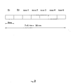
- the message is for example composed of 56 bits, ie 16 synchronization bits (2 bytes: S1 and S2) and 40 bits of information (5 bytes) (see Figure 2); it lasts 2.24 ms at the telegraph speed of 25 Kbaud used.
- Each useful octect can transmit one of 10 pieces of information. In other words, among the 256 possible 8-bit combinations, only ten combinations are normally authorized. If the coder cannot determine the information to be transmitted, it transmits an 11th combination called "questionable aspect".
- the coding precautions thus taken guarantee a "Hamming distance" of 4 for a simple message: in other words, to transform a correct message into a false interpretable message, it is necessary to distort at least 4 bits.
- One of the main functions of the ground equipment 5 is to reliably determine the value of the code to be given to each byte of the message on the basis of information from channel 11 (signal color, type signal, speed to be observed, etc.).
- the coding is carried out in two different ways on the basis of duplicated information so that half of the message sent is coded in one way and the other half in the other way; the emission of coherent messages thus reveals the similarity of the two codings and consequently their accuracy.
- the information 31 coming from the channel 11 is coded in two different ways in a coding means 33, provided in a manner known per se with a clock 35.
- the bits of the message thus coded are sent, one message out of two being inverted, in a shift register 37 which puts them in series to transmit them, via a logic gate 39 reversing every other message, to a modulator 41 to define there the frequency to be injected, after amplification at 43 and galvanic isolation at 45, in the loop 47 of the transmission beacon 9 (0: 90KHz; 1: 110 KHz).
- the ground equipment thus comprises a means of controlling the correct refreshment of the shift register 33, which comprises the logic gate 39 controlled by the clock 35.
- ground equipment 5 Another main function of the ground equipment 5 is to guarantee in a reliable manner the detection of the on-board emission beacon by a sufficient emission level and by a correct modulation frequency. Furthermore, it must guarantee the emission of a stop message each time the channel signal 11 is closed.
- the primary loop 47 of the beacon 9 comprises an intensity transformer 51 tuned in series, which supplies its secondary winding, via a rectification and filtering cell 53, with a proportional direct current at the level of the emitted magnetic field which is brought into the housing 5.
- the direct current is brought to a toroid 57 called saturable magnetic amplifier where it is compared to a predetermined threshold 59. If the direct current is too weak, it is ie if the amplitude of the magnetic field is insufficient, said magnetic amplifier 57 is unbalanced and controls an external relay 61 which actuates the stop signal on the channel.
- the ground equipment comprises a circuit 63.
- This essentially comprises at least one clock 65, a means for reading the modulated frequency, a means for picking up coded messages, a means for decoding them, a means of selecting and classifying the decoded messages into three categories: (a) non-conforming messages to be rejected, (b) conforming messages involving stopping the vehicle and (c) conforming messages allowing passage of the vehicle, a means allowing the link of the clock frequency to the variations of the modulated frequency so that the clock frequency allows a more or less rapid sampling of the message thereby providing messages classified in (b) or ( c) if the modulated frequency is correct or in (a) if the modulated frequency has undergone any variation, said control means being connected to a means for controlling a safety signal.
- the signal thus obtained (a, b or c) is sent via an interface 67 to a magnetic amplifier of the above-mentioned type, preferably the same as that which is used for controlling the emission level. It is compared there with a control current for closing the stop signal 69. If the signal has been classified in (a), it does not correspond to the signal 69 and the magnetic amplifier 57 actuates the signal control relay stop. If the signal has been classified in (b) or (c), the magnetic amplifier compares it to the state (open or closed) of the stop signal 69 and actuates the control relay 61 if necessary.
- the tag 9 consists of a single turn 91 of stainless steel 80 cm long forming the secondary circuit of a transformer with magnetic circuit the primary circuit 47 from which the modulated current is injected.
- the primary winding is advantageously mounted on the axis 93 disposed inside the single turn 91, perpendicular to the plane of the latter.
- the single, sufficiently rigid turn is mounted between the rails by means of two opposite lugs 95 and 97 in an S shape.
- the primary circuit 47 is cast in a housing fixed below the fixing lug 95.
- the tag 9 is mounted between the rails 101 and 102 and is offset from the axis of the track so as to define the direction of traffic.
- the frequency modulated voltage is picked up at the terminals of an antenna 13 mounted below each driving position of the vehicle, that is to say in an off-center manner on the left, if the beacons are mounted in an off-center manner on the left, in the direction of traffic.
- the antenna 13 , 15 consists two windings 131 and 133, one of which is wound from the left and the other from the right.
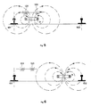
- FIG. 5 when the antenna passes over a beacon which is intended for the chosen direction of travel, the magnetic fluxes which are opposite with respect to each other are picked up in opposite windings and are of this fact in phase concordance.
- FIG. 6 when the antenna picks up the field emitted by a counter-track beacon 9, this crosses the two opposite windings and the currents obtained in the windings 131 and 133 are therefore in phase opposition.
- a microcomputer can be responsible for managing the reception of beacons 9.
- the on-board equipment comprises at least one microcomputer 151, 152, 153 responsible for managing the reception of the beacons, that is to say for detecting the presence of a beacon, for reading at least two identical consecutive messages, to verify compliance with the byte of information code (decades), which amounts to verifying the refreshment of the shift register and to comparing the two codings carried out on the ground, and if successful, to transmit on a high speed computer bus , according to its own protocol, the information captured in the channel, without decoding it. If a beacon whose message is unintelligible is detected, a special "transmission alarm" message is sent on the computer bus.
- a microcomputer 151, 152, 153 responsible for managing the reception of the beacons, that is to say for detecting the presence of a beacon, for reading at least two identical consecutive messages, to verify compliance with the byte of information code (decades), which amounts to verifying the refreshment of the shift register and to comparing the two codings carried out on the ground, and if successful,
- one or more computers can draw the information necessary to carry out their own walking control program.
- the on-board equipment may also include other auxiliary circuits such as the control of the braking curve 167, 168 and 169 with majority vote 170 and inputs of additional parameters in the computers 155, 156 and 157, such as taking a speed or whatever.
- auxiliary circuits such as the control of the braking curve 167, 168 and 169 with majority vote 170 and inputs of additional parameters in the computers 155, 156 and 157, such as taking a speed or whatever.
- circuits described above also include all of the ancillary means known per se, such as power supplies, regulation loops and the like, the representations of the figures giving only the operating principle according to the invention.
Landscapes
- Engineering & Computer Science (AREA)
- Mechanical Engineering (AREA)
- Train Traffic Observation, Control, And Security (AREA)
- Electric Propulsion And Braking For Vehicles (AREA)
- Radar Systems Or Details Thereof (AREA)
- Near-Field Transmission Systems (AREA)
- Signal Processing For Digital Recording And Reproducing (AREA)
Abstract
Description
La présente invention est relative à une installation pour la transmission ponctuelle de données entre la voie et un véhicule circulant sur celle-ci, qui comporte un émetteur fixé sur la voie et un récepteur logé dans le véhicule tel qu'un véhicule de chemin de fer, tram, métropolitain, ... etc.The present invention relates to an installation for the punctual transmission of data between the track and a vehicle traveling on it, which comprises a transmitter fixed on the track and a receiver housed in the vehicle such as a railway vehicle , tram, metropolitan, ... etc.
Traditionnellement, la circulation des véhicules de chemin de fer est réglée par les signaux implantés le long de la voie, ce qui garantit un degré de sécurité élevé.Traditionally, the traffic of railway vehicles is regulated by the signals located along the track, which guarantees a high degree of safety.
Cependant, la responsabilité du respect des consignes données par les installations de signalisation est entièrement confiée au conducteur qui doit l'assumer dans des conditions parfois difficiles: circulation dans le brouillard ou pendant des chutes de neige, soleil rasant, etc...However, the responsibility for respecting the instructions given by the signaling installations is entirely entrusted to the driver who must assume it in sometimes difficult conditions: traffic in fog or during snowfall, low sun, etc ...
Il est donc important pour la sécurité du trafic, de doter les postes de conduite d'un équipement dont la double fonction est de répéter à bord l'aspect de la signalisation, et de contrôler l'action du conducteur dans les différentes situations créées le long du parcours par l'aspect des signaux; en cas de négligence éventuelle de la part du conducteur, le système arrête le véhicule automatiquement.It is therefore important for traffic safety, to equip the driving positions with equipment whose double function is to repeat on board the aspect of the signaling, and to control the action of the driver in the different situations created the along the route by the appearance of the signals; in the event of possible negligence on the part of the driver, the system stops the vehicle automatically.
Par ailleurs, une transmission à haute capacité d'information est nécessaire pour réaliser un contrôle de vitesse efficace.In addition, a high information capacity transmission is necessary to achieve effective speed control.
En effet, il faut au moins pouvoir transmettre ponctuellement des informations sur les aspects des signaux, la pente de la voie, la vitesse à respecter et la distance au prochain signal, et la vitesse de la ligne.Indeed, it is necessary at least to be able to transmit punctually information on the aspects of the signals, the slope of the track, the speed to respect and the distance to the next signal, and the speed of the line.
Les équipments de transmission et de traitement des informations doivent présenter un très haut degré de sécurité de fonctionnement et ce dans des conditions très dures: températures extrêmes, vibrations, chocs, humidité, poussières, environnement électro-magnétique perturbateur, etc... De plus, ils doivent présenter une grande disponibilité, c'est-à-dire qu'ils ne peuvent donner lieu qu'à un minimum d'incidents ou d'actions intempestives (par exemple, commandes erronées de freinage) qui entraîneraient des perturbations inadmissibles du trafic. Enfin, cette transmission voie-machine doit pouvoir fonctionner jusqu'aux plus hautes vitesses de circulation.The equipment for transmitting and processing information must have a very high degree of operational safety under very harsh conditions: extreme temperatures, vibrations, shocks, humidity, dust, disturbing electro-magnetic environment, etc ... In addition, they must be widely available, i.e. they can only give rise to a minimum of incidents or untimely actions ( (for example, wrong brake controls) which would cause unacceptable traffic disruptions. Finally, this track-to-machine transmission must be able to operate up to the highest traffic speeds.
L'une des difficultés, dans le cadre d'un fonctionnement en sécurité, réside dans la sélection des émetteurs adéquats fixés sur la voie parcourue par le véhicule et correspondant à son sens de marche . Par ailleurs, une autre difficulté réside dans la transmission à un niveau suffisant pour garantir une réception sûre des messages par le récepteur logé dans le véhicule.One of the difficulties, in the context of safe operation, lies in the selection of suitable transmitters fixed on the path traveled by the vehicle and corresponding to its direction of travel. Another difficulty lies in transmitting at a level sufficient to guarantee safe reception of messages by the receiver housed in the vehicle.
On connaît une installation pour la transmission ponctuelle de données entre la voie et un véhicule circulant sur celle-ci, qui comporte un émetteur passif (dénommé transpondeur) fixé sur la voie et un récepteur logé dans le véhicule circulant sur celle-ci, l'émetteur passif étant activé par un niveau d'émission provenant du véhicule. De cette manière, on est certain de recevoir les informations de l'émetteur correct. Par ailleurs, l'absorption de l'énergie d'émission par l'émetteur passif peut être détectée ce qui permet à un calculateur de constater la présence d'un émetteur. Cette installation connue en soi satisfait les exigences posées ci-dessus, mais elle est très encombrante et consomme beaucoup d'énergie pour l'activation des émetteurs passifs. De plus, il y a lieu de s'assurer d'un niveau énergétique suffisant transmis vers les émetteurs passifs, et ce en tenant compte des irrégularités dans les voies et, de ce fait, des variations de l'écart entre l'antenne émettrice d'activation et l'émetteur passif à activer. En outre, l'installation connue est complexe et onéreuse.An installation is known for the punctual transmission of data between the track and a vehicle traveling on it, which comprises a passive transmitter (called transponder) fixed on the track and a receiver housed in the vehicle traveling on it, the passive transmitter being activated by an emission level from the vehicle. In this way, we are sure to receive the information from the correct transmitter. Furthermore, the absorption of the emission energy by the passive transmitter can be detected, which allows a computer to note the presence of a transmitter. This known installation satisfies the above requirements, but it is very bulky and consumes a lot of energy for the activation of passive transmitters. In addition, it is necessary to ensure a sufficient energy level transmitted to the passive transmitters, and this taking into account the irregularities in the channels and, therefore, variations in the difference between the transmitting antenna. and the passive transmitter to activate. In addition, the known installation is complex and expensive.
Par conséquent, la présente invention vise à fournir une nouvelle installation du type susmentionné répondant aux exigences de sécurité précitées et remplissant les fonctions requises.Consequently, the present invention aims to provide a new installation of the aforementioned type meeting the aforementioned security requirements and performing the required functions.
Un autre but de la présente invention vise à fournir une installation du type susmentionné qui pallie les inconvénients des installations de l'état de la technique.Another object of the present invention is to provide an installation of the aforementioned type which overcomes the drawbacks of prior art installations.
Un autre but de la présente invention vise à fournir une installation du type susmentionné qui permet de sélectionner, en toute sécurité, les émetteurs corrects solidaires de la voie, en rejettant les émetteurs d'une voie parallèle ou correspondant au sens de marche inverse; qui permet de garantir un niveau d'émission suffisant, faute de quoi un signal de sécurité est enclenché; qui permet de garantir une fréquence d'émission correcte, faute de quoi un signal de sécurité est enclenché; et qui permet un codage et décodage corrects des informations transmises ainsi qu'un traitement en sécurité de celles-ci.Another object of the present invention aims to provide an installation of the aforementioned type which makes it possible to safely select the correct transmitters integral with the channel, by rejecting the transmitters from a parallel channel or corresponding to the reverse direction of travel; which guarantees a sufficient emission level, failing which a safety signal is triggered; which guarantees a correct transmission frequency, failing which a safety signal is triggered; and which allows correct coding and decoding of the transmitted information as well as a secure processing thereof.
Les buts de la présente invention sont atteints par une installation de transmission ponctuelle de données entre la voie et un véhicule circulant sur celle-ci, constituée par un équipement de sol fixé sur la voie comportant un émetteur qui transmet les informations codées d'un signal de voie à l'aide d'une balise d'émission, ainsi que d'un équipement de bord logé dans le véhicule comportant un récepteur relié à au moins une antenne de réception fixée en dessous du véhicule de manière à correspondre avec la balise d'émission, et au moins un calculateur pour le décodage et le traitement des informations reçues, ledit calculateur étant raccordé à un tableau d'affichage et de lecture ainsi qu'à un dispositif de commande des freins, caractérisée en ce que l'équipement de sol comporte au moins un moyen de codage binaire séquentiel des informations de signalisation de voie, un émetteur actif à modulation de fréquence d'un champ magnétique, un moyen de comparaison à un seuil de l'amplitude du champ magnétique émis et un moyen de contrôle de la fréquence émise à l'aide d'une balise d'émission, le moyen de comparaison de l'amplitude du champ magnétique émis et le moyen de contrôle de la fréquence d'émission étant raccordés à un moyen de commande d'un signal de sécurité, tel que la commutation au rouge du signal de la voie.The aims of the present invention are achieved by an installation for the punctual transmission of data between the track and a vehicle traveling on it, constituted by ground equipment attached to the track comprising a transmitter which transmits the coded information of a signal lane using a transmitter beacon, as well as on-board equipment housed in the vehicle comprising a receiver connected to at least one receiving antenna fixed below the vehicle so as to correspond with the beacon d transmission, and at least one computer for decoding and processing the information received, said computer being connected to a display and reading board as well as to a brake control device, characterized in that the equipment for ground comprises at least one means of sequential binary coding of the signaling information of the channel, an active transmitter with frequency modulation of a magnetic field, a means of comparison with a threshold of the amplitude of the magnetic field emitted and a means for controlling the frequency emitted using a transmitting beacon, the means for comparing the amplitude of the magnetic field emitted and the means for transmission frequency control being connected to a means for controlling a safety signal, such as switching the signal of the channel to red.
Grâce à l'installation de transmission selon la présente invention, dans laquelle le niveau d'émission et la fréquence d'émission sont contrôlés, il est possible de transmettre les informations codées de manière sûre.By virtue of the transmission installation according to the present invention, in which the emission level and the transmission frequency are controlled, it is possible to transmit the coded information securely.
On peut encore augmenter la sécurité de fonctionnement de l'installation selon la présente invention, en utilisant un codage particulier des signaux, dans lequel la distance d'Hamming est élevée. Avantageusement, un message se compose de 7 octets dont deux octets de synchronisation et 5 octets d'information dont chacun peut transmettre une information parmi 10, de manière à conserver une "distance de Hamming" de 4. Les précautions de codage ainsi prises garantissent que pour transformer un message correct en un message faux interprétable, il faut transformer au moins 4 bits. On peut aussi réaliser le codage de deux manières différentes sur base d'informations dédoublées de manière qu'une moitié du message émis soit codée d'une façon et l'autre moitié de l'autre façon; l'émission de messages cohérents révèle alors la similitude des deux résultats et par conséquent leur exactitude.The operating safety of the installation according to the present invention can be further increased, by using a particular coding of the signals, in which the Hamming distance is high. Advantageously, a message consists of 7 bytes, including two synchronization bytes and 5 bytes of information, each of which can transmit one of 10 pieces of information, so as to maintain a "Hamming distance" of 4. The coding precautions thus taken guarantee that to transform a correct message into a false interpretable message, it is necessary to transform at least 4 bits. Coding can also be carried out in two different ways on the basis of duplicated information so that half of the message sent is coded in one way and the other half in the other way; the issuance of consistent messages then reveals the similarity of the two results and therefore their accuracy.
Selon une forme d'exécution particulièrement préférée, le moyen de comparaison de l'amplitude du champ magnétique émis à l'aide d'un circuit LC accordé comporte un transformateur d'intensité dont l'enroulement primaire se trouve dans le circuit primaire du transformateur du circuit LC accordé, et un redresseur dont le courant continu sortant qui est proportionnel à l'amplitude du champ est envoyé via un interface adéquat sur un tore dénommé amplificateur magnétique qui déclenche un signal de sécurité via un relais de commande lorsque ledit courant continu est inférieur à un courant continu de seuil généré indépendamment.According to a particularly preferred embodiment, the means for comparing the amplitude of the magnetic field emitted using a tuned LC circuit comprises an intensity transformer whose primary winding is located in the primary circuit of the transformer of the tuned LC circuit, and a rectifier whose outgoing direct current which is proportional to the amplitude of the field is sent via a suitable interface to a toroid called magnetic amplifier which triggers a safety signal via a control relay when said direct current is less than an independently generated threshold DC current.
De préférence, le moyen de contrôle de la fréquence modulée comporte essentiellement au moins, une horloge, un moyen de lecture de la fréquence modulée, un moyen de captage des messages codés, un moyen de décodage de ceux-ci, un moyen de sélection et de classement des messages décodés en trois catégories: (a) messages non conformes à rejeter, (b) messages conformes impliquant l'arrêt du véhicule et (c) messages conformes permettant le passage du véhicule, un moyen permettant la liaison de la fréquence d'horloge aux variations de la fréquence modulée de telle sorte que la fréquence d'horloge permet un échantillonnage plus ou moins rapide du message en fournissant ainsi des messages classés en (b) ou (c) si la fréquence modulée est correcte ou en (a) si la fréquence modulée a subi une quelconque variation, ledit moyen de contrôle étant relié à un moyen de commande d'un signal de sécurité.Preferably, the means for controlling the modulated frequency essentially comprises at least, a clock, a means for reading the modulated frequency, a means for capturing coded messages, a means for decoding them, a means for selecting and classifying the decoded messages into three categories: (a) non-conforming messages to be rejected, (b) conforming messages involving stopping the vehicle and (c) conforming messages allowing the passage of the vehicle, a means allowing the link of the clock frequency to the variations of the modulated frequency so that the clock frequency allows a more or less rapid sampling of the message thereby providing messages classified in (b) or (c) if the modulated frequency is correct or in (a) if the modulated frequency has undergone any variation, said control means being connected to a means for controlling a safety signal.
Avantageusement, le signal classé en (a), (b) ou (c) est comparé dans un amplificateur magnétique, de préférence le même amplificateur magnétique qui sert de moyen de comparaison de l'amplitude du champ magnétique émis, à une référence dépendant de l'état réel du signal de la voie, ledit amplificateur magnétique pouvant déclencher un signal de sécurité tel qu'un signal d'arrêt rouge.Advantageously, the signal classified in (a), (b) or (c) is compared in a magnetic amplifier, preferably the same magnetic amplifier which serves as a means of comparing the amplitude of the magnetic field emitted, with a reference depending on the actual state of the channel signal, said magnetic amplifier being able to trigger a safety signal such as a red stop signal.
Comme déjà mentionné précédemment, la balise d'émission est montée sur la voie en étant avantageusement décalée vers la gauche par rapport à l'axe de la voie, vu dans le sens de circulation du véhicule; de cette manière, une voie utilisée dans les deux sens de circulation peut comporter des balises correspondant au sens de circulation voulu,de chaque côté de l'axe de la voie.As already mentioned above, the emission beacon is mounted on the track, being advantageously offset to the left with respect to the axis of the track, seen in the direction of travel of the vehicle; in this way, a lane used in both directions of traffic may include markers corresponding to the desired direction of traffic, on each side of the axis of the lane.
L'équipement de bord comporte, entre autres, un récepteur relié à au moins une antenne de réception extérieure fixée en dessous du véhicule, décalée par rapport à l'axe de la voie, vu dans le sens de la marche. Chaque antenne de réception consiste avantageusement en un bobinage à enroulement gauche et en un bobinage à enroulement droit, montés l'un à côté de l'autre, sur un même axe. Cet agencement permet tout particulièrement de rejeter les balises d'émission correspondant au sens de la circulation inverse ou à des voies parallèles. Cet agencement particulier de l'antenne permet donc de sélectionner en toute sécurité la balise d'émission adéquate. En effet, les flux magnétiques perçus par les enroulements gauche et droit d'une antenne sont en concordance de phase, lorsque la balise d'émission correcte passe en dessous de l'antenne; par contre, si une balise parasite d'une voie parallèle ou de l'autre sens de circulation du véhicule est captée par l'antenne susmentionnée, les deux enroulements de celle-ci captent un flux magnétique de même orientation et, par conséquent, les signaux transmis par lesdits enroulements opposés sont en opposition de phase. Ceci permet au dispositif de bord de sélectionner les balises adéquates en toute sécurité.The on-board equipment comprises, inter alia, a receiver connected to at least one external receiving antenna fixed below the vehicle, offset with respect to the axis of the track, seen in the direction of travel. Each receiving antenna advantageously consists of a left-winding winding and a right-winding winding, mounted one next to the other, on the same axis. This arrangement makes it possible in particular to reject the emission beacons corresponding to the direction of reverse traffic or to parallel tracks. This arrangement particular antenna therefore makes it possible to safely select the appropriate transmission beacon. Indeed, the magnetic fluxes perceived by the left and right windings of an antenna are in phase agreement, when the correct emission beacon passes below the antenna; on the other hand, if a parasitic beacon of a parallel track or of the other direction of circulation of the vehicle is picked up by the above-mentioned antenna, the two windings of the latter pick up a magnetic flux of the same orientation and, consequently, the signals transmitted by said opposite windings are in phase opposition. This allows the on-board device to safely select the appropriate tags.
Les signaux captés par l'antenne de réception à bord du véhicule sont ensuite décodés et traités par des calculateurs électroniques, éventuellement doublés ou triplés pour des raisons de sécurité. L'équipment de bord peut également comporter un capteur de vitesse dont les signaux seront également traités dans les calculateurs pour le contrôle de marche moyennant un programme destiné à cet effet.The signals received by the receiving antenna on board the vehicle are then decoded and processed by electronic computers, possibly doubled or tripled for safety reasons. The on-board equipment may also include a speed sensor, the signals of which will also be processed in the computers for the speed control by means of a program intended for this purpose.
Les variables de sortie sont l'allumage des lampes au tableau de bord et la commande de freinage lorsque le conducteur ne respecte pas les consignes.The output variables are the lighting of the dashboard lamps and the brake control when the driver does not comply with the instructions.
D'autres détails de la présente invention apparaîtront dans la description qui suit d'une forme d'exécution particulière, à l'appui des dessins dans lesquels:
- - la figure 1 représente une vue générale schématique de l'installation selon la présente invention;
- - la figure 2 représente schématiquement un message;
- - la figure 3 est une vue schématique de fonctionnement de l'équipement de sol, selon une forme d'exécution préférée de l'invention;
- - la figure 4 est une vue en coupe d'une balise d'émission;
- - la figure 5 représente le franchissement d'une balise normale par l'antenne de réception de l'équipement de bord;
- - la figure 6 représente le franchissement d'une balise d'émission parasite par l'antenne de réception; et
- - la figure 7 est une vue schématique du principe de fonctionnement de l'équipement de bord.
- - Figure 1 shows a schematic general view of the installation according to the present invention;
- - Figure 2 schematically represents a message;
- - Figure 3 is a schematic view of the operation of the ground equipment, according to a preferred embodiment of the invention;
- - Figure 4 is a sectional view of a transmission beacon;
- - Figure 5 shows the crossing of a normal beacon by the receiving antenna of the on-board equipment;
- - Figure 6 shows the crossing of a parasitic transmitting beacon by the receiving antenna; and
- - Figure 7 is a schematic view of the operating principle of the on-board equipment.
Dans les figures, des repères identiques sont utilisés pour des éléments identiques ou analogues.In the figures, identical references are used for identical or similar elements.
En référence à la figure 1, l'installation se compose d'un équipement de bord 1 monté dans un véhicule 3 et d'un équipement de sol 5 placé le long de la voie 7.With reference to FIG. 1, the installation consists of on-
L'équipement de sol code et émet en permanence, à travers une balise 9, un message binaire répété indéfiniment, codant une information, provenant d'un signal de voie 11, par exemple.The ground equipment continuously codes and transmits, through a
Une antenne 13, 15 installée sous chaque poste de conduite du véhicule, permet de capter lors du passage au-dessus d'une balise 9, le message binaire qu'elle émet.An
L'équipement de bord 1 comprend des circuits de réception, de démodulation et de validation du message reçu sur l'antenne, des circuits de traitement des informations captées dans la voie, et en provenance du poste de conduite et du capteur de vitesse 17, enfin des circuits de commande de freinage 19, et des circuits donnant au conducteur des informations en provenance de la voie et des consignes.The on-
La transmission est réalisée par modulation de la fréquence du champ magnétique rayonné par une boucle accordée à 100 KHz.Transmission is achieved by modulating the frequency of the magnetic field radiated by a loop tuned to 100 KHz.
Le message est par exemple composé de 56 bits soit 16 bits de synchronisation (2 octets: S₁ et S₂) et 40 bits d'informations (5 octets) (voir figure 2); il dure 2 ,24 ms à la vitesse télégraphique de 25 Kbaud utilisée. Chaque octect utile peut transmettre une information parmi 10. Autrement dit, parmi les 256 combinaisons possibles de 8 bits, seules dix combinaisons sont normalement autorisées. Dans le cas où le codeur ne peut déterminer l'information à transmettre, il transmet une 11ème combinaison appelée "aspect douteux". Les précautions de codage ainsi prises garantissent une "distance de Hamming" de 4 pour un message simple: autrement dit, pour transformer un message correct en un message faux interprétable, il faut fausser au moins 4 bits.The message is for example composed of 56 bits, ie 16 synchronization bits (2 bytes: S₁ and S₂) and 40 bits of information (5 bytes) (see Figure 2); it lasts 2.24 ms at the telegraph speed of 25 Kbaud used. Each useful octect can transmit one of 10 pieces of information. In other words, among the 256 possible 8-bit combinations, only ten combinations are normally authorized. If the coder cannot determine the information to be transmitted, it transmits an 11th combination called "questionable aspect". The coding precautions thus taken guarantee a "Hamming distance" of 4 for a simple message: in other words, to transform a correct message into a false interpretable message, it is necessary to distort at least 4 bits.
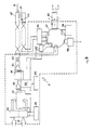
L'une des fonctions principales de l'équipement de sol 5 (figure 3) est de déterminer de manière sûre la valeur du code à donner à chaque octet du message sur base des informations en provenance de la voie 11 (couleur du signal, type de signal, vitesse à respecter, etc...). Dans ce but, le codage est réalisé de deux manières différentes sur base d'informations dédoublées de manière à ce qu'une moitié du message émis, soit codée d'une façon, et l'autre moitié de l'autre façon; l'émission de messages cohérents révèle ainsi la similitude des deux codages et par conséquent leur exactitude.One of the main functions of the ground equipment 5 (FIG. 3) is to reliably determine the value of the code to be given to each byte of the message on the basis of information from channel 11 (signal color, type signal, speed to be observed, etc.). For this purpose, the coding is carried out in two different ways on the basis of duplicated information so that half of the message sent is coded in one way and the other half in the other way; the emission of coherent messages thus reveals the similarity of the two codings and consequently their accuracy.
Les informations 31 provenant de la voie 11 sont codées de deux manières différentes dans un moyen de codage 33, muni de manière connue en soi d'une horloge 35. Les bits du message ainsi codés sont envoyés , un message sur deux étant inversé, dans un registre à décalage 37 qui les met en série pour les transmettre, via une porte logique 39 inversant un message sur deux, à un modulateur 41 pour y définir la fréquence à injecter, après amplification en 43 et isolation galvanique en 45, dans la boucle 47 de la balise d'émission 9 (0:90KHz; 1:110 KHz). L'équipement de sol comporte ainsi un moyen de contrôle du bon rafraîchissement du registre à décalage 33, qui comporte la porte logique 39 commandée par l'horloge 35.The
Une autre fonction principale de l'équipement de sol 5 est de garantir de manière sûre la détection de la balise d'émission à bord par un niveau d'émission suffisant et par une fréquence de modulation correcte. Par ailleurs, il doit garantir l'émission d'un message d'arrêt chaque fois que le signal de voie 11 est fermé.Another main function of the
En vue de contrôler le niveau d'émission, la boucle primaire 47 de la balise 9 comporte un transformateur d'intensité 51 accordé en série, qui fournit à son enroulement secondaire, via une cellule de redressage et de filtrage 53, un courant continu proportionnel au niveau de champ magnétique émis qui est amené dans le boîtier 5. Moyennant un interface 55 le courant continu est amené sur un tore 57 dénommé amplificateur magnétique saturable où il est comparé à un seuil prédéterminé 59. Si le courant continu est trop faible, c'est-à-dire si l'amplitude du champ magnétique est insuffisante, ledit amplificateur magnétique 57 est déséquilibré et commande un relais extérieur 61 qui actionne le signal d'arrêt sur la voie.In order to control the emission level, the
En vue de contrôler la fréquence d'émission, l'équipment de sol comporte un circuit 63. Celui-ci comporte essentiellement au moins une horloge 65, un moyen de lecture de la fréquence modulée,un moyen de captage des messages codés, un moyen de décodage de ceux-ci, un moyen de sélection et de classement des messages décodés en trois catégories: (a) messages non conformes à rejeter, (b) messages conformes impliquant l'arrêt du véhicule et (c) messages conformes permettant le passage du véhicule, un moyen permettant la liaison de la fréquence d'horloge aux variations de la fréquence modulée de telle sorte que la fréquence d'horloge permet un échantillonnage plus ou moins rapide du message en fournissant ainsi des messages classés en (b) ou (c) si la fréquence modulée est correcte ou en (a) si la fréquence modulée a subi une quelconque variation, ledit moyen de contrôle étant relié à un moyen de commande d'un signal de sécurité.In order to control the transmission frequency, the ground equipment comprises a
Ledit circuit 63 permet de faire varier la fréquence d'horloge en fonction des variations éventuelles de la fréquence modulée. Il capte également le message en amont du modulateur. Lorsque la fréquence modulée varie, l'échantillonnage du message à transmettre varie également et le message lu est un message non conforme. Lorsque la fréquence d'émission est correcte, l'échantillonnage s'effectue normalement et le message lu après échantillonnement est cohérent. Le circuit 63 effectue ensuite un classement des messages obtenus en trois catégories:
- (a) messages non conformes au code, à rejeter;
- (b) messages conformes au code, signifiant l'arrêt;
- (c) messages, conformes au code, signifiant le passage.
- (a) messages that do not comply with the code, to be rejected;
- (b) messages conforming to the code, signifying the stop;
- (c) messages, conforming to the code, signifying the passage.
Le signal ainsi obtenu (a, b ou c) est envoyé via un interface 67 sur un amplificateur magnétique du type susmentionné, de préférence le même que celui qui est utilisé pour le contrôle du niveau d'émission. Il y est comparé à un courant de contrôle de la fermeture du signal d'arrêt 69. Si le signal a été classé en (a), il ne correspond pas au signal 69 et l'amplificateur magnétique 57 actionne le relais de commande du signal d'arrêt. Si le signal a été classé en (b) ou (c), l'amplificateur magnétique le compare à l'état (ouvert ou fermé) du signal d'arrêt 69 et actionne le relais de commande 61 si nécessaire.The signal thus obtained (a, b or c) is sent via an
En référence à la figure 4 et selon une forme d'exécution préférée de la présente invention, la balise 9 est constituée d'une spire unique 91 en acier inoxydable de 80 cm de long formant le circuit secondaire d'un transformateur à circuit magnétique dans le circuit primaire 47 duquel le courant modulé est injecté. L'enroulement primaire est avantageusement monté sur l'axe 93 disposé à l'intérieur de la spire unique 91, perpendiculairement au plan de celle-ci. La spire unique, suffisamment rigide est montée entre les rails moyennant deux pattes opposées 95 et 97 en forme de S. Avantageusement, le circuit primaire 47 est coulé dans un boîtier fixé en dessous de la patte de fixation 95.Referring to Figure 4 and according to a preferred embodiment of the present invention, the
La balise 9 est montée entre les rails 101 et 102 et est décentrée par rapport à l'axe de la voie de manière à définir le sens de circulation.The
La tension modulée en fréquence est captée aux bornes d'une antenne 13 montée en dessous de chaque poste de conduite du véhicule, c'est-à-dire de manière décentrée à gauche, si les balises sont montées de manière décentrée à gauche, dans le sens de circulation.The frequency modulated voltage is picked up at the terminals of an
Selon une forme d'éxecution avantageuse, et en vue d'éviter le captage de signaux provenant d'une balise parasite, par exemple une balise d'une autre voie ou de la contre-voie (en sens inverse), l'antenne 13, 15 se compose de deux bobinages 131 et 133 dont l'un est enroulé par la gauche et l'autre par la droite. Ainsi, comme représenté à la figure 5, lorsque l'antenne passe sur une balise qui est destinée au sens de marche choisi, les flux magnétiques qui sont opposés l'un par rapport à l'autre sont captés dans des enroulements opposés et sont de ce fait en concordance de phase. Par contre, comme représenté à la figure 6, lorsque l'antenne capte le champ émis par une balise 9 de contre-voie, celui-ci traverse les deux bobinages opposés et les courants obtenus dans les bobinages 131 et 133 sont de ce fait en opposition de phase. Un micro-calculateur peut être chargé de gérer la réception des balises 9.According to an advantageous embodiment, and in order to avoid picking up signals coming from a parasitic beacon, for example a beacon from another channel or from the counter-channel (in the opposite direction), the
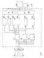
L'équipement de bord comporte au moins un micro-calculateur 151, 152, 153 chargé de gérer la réception des balises, c'est-à-dire de détecter la présence d'une balise, de lire au moins deux messages consécutifs identiques, de vérifier la conformité au code des octets d'informations (décades) ce qui revient à vérifier le rafraîchissement du registre à décalage et à comparer les deux codages réalisés au sol, et en cas de succès, de transmettre sur un bus informatique à grande vitesse, suivant un protocole propre, les informations captées dans la voie, sans les décoder. En cas de détection d'une balise dont le message est inintelligible, un message spécial "alarme transmission" est envoyé sur le bus informatique.The on-board equipment comprises at least one
En finale, un ou plusieurs calculateurs (155, 156, 157) peuvent puiser les informations nécessaires pour réaliser le programme de contrôle de marche qui leur est propre.In the end, one or more computers (155, 156, 157) can draw the information necessary to carry out their own walking control program.
Etant donné les impératifs de sécurité et de disponibilité, toutes les fonctions décrites jusqu'à présent ont été triplées et les variables de sortie des trois chaînes ainsi formées I, II et III (commande de freinage 161, allumage de lampes au tableau de bord 163, enregistrement 165) sont soumises à un vote majoritaire appelé 2 de 3, c'est-à-dire que la concordance des résultats de 2 calculateurs sur les 3, concernant une variable de sortie, permet son actionnement (159).Given the security and availability requirements, all the functions described so far have been tripled and the output variables of the three chains thus formed I, II and III (
On peut également réaliser, à intervalles réguliers des tests destinés à détecter des défauts dans les circuits de traitement.It is also possible to carry out, at regular intervals, tests intended to detect faults in the processing circuits.
L'équipement de bord peut également comporter d'autres circuits annexes tels que le contrôle de la courbe de freinage 167, 168 et 169 avec vote majoritaire 170 et des entrées de paramètres complémentaires dans les calculateurs 155, 156 et 157, comme une prise de vitesse ou autre.The on-board equipment may also include other auxiliary circuits such as the control of the
Il est bien évident que les circuits décrits ci-dessus comportent également tous les moyens annexes connus en soi tels que alimentations, boucles de régulation et autres, les représentations des figures ne donnant que le principe de fonctionnement selon l'invention.It is obvious that the circuits described above also include all of the ancillary means known per se, such as power supplies, regulation loops and the like, the representations of the figures giving only the operating principle according to the invention.
Claims (10)
Priority Applications (10)
| Application Number | Priority Date | Filing Date | Title |
|---|---|---|---|
| AT86870091T ATE56403T1 (en) | 1986-06-24 | 1986-06-24 | DEVICE FOR POINT-FORM TRANSMISSION OF DATA BETWEEN THE TRACK AND A TRAIN. |
| EP86870091A EP0252199B1 (en) | 1986-06-24 | 1986-06-24 | Installation for the point-to-point transmission of data between a track and a vehicle passing over it |
| DE8686870091T DE3674205D1 (en) | 1986-06-24 | 1986-06-24 | DEVICE FOR DOT-SIGNAL TRANSFER OF DATA BETWEEN THE TRACK AND A TRAIN. |
| CA000540377A CA1290810C (en) | 1986-06-24 | 1987-06-23 | Installation for the localized transmission of data between a circulation lane and a vehicle circulating on the lane |
| DZ870106A DZ1099A1 (en) | 1986-06-24 | 1987-06-23 | Installation for the punctual transmission of data between the track and a vehicle traveling on it. |
| MA21253A MA21012A1 (en) | 1986-06-24 | 1987-06-23 | Installation for the punctual transmission of data between the track and a vehicle traveling on it |
| ES878701838A ES2006769A6 (en) | 1986-06-24 | 1987-06-23 | Installation for the point-to-point transmission of data between a track and a vehicle passing over it. |
| IE167787A IE63127B1 (en) | 1986-06-24 | 1987-06-24 | Installation for the transmission of data between a track and a vehicle travelling on it |
| PT85160A PT85160B (en) | 1986-06-24 | 1987-06-24 | INSTALLATION FOR THE DATA TRANSMISSION OF DATA BETWEEN VIA AND A VEHICLE CIRCUMLATING ABOUT IT |
| TNTNSN87122A TNSN87122A1 (en) | 1986-06-24 | 1987-11-02 | INSTALLATION FOR THE PUNCTUAL TRANSMISSION OF DATA BETWEEN THE TRACK AND A VEHICLE TRAFFICING THEREON |
Applications Claiming Priority (2)
| Application Number | Priority Date | Filing Date | Title |
|---|---|---|---|
| EP86870091A EP0252199B1 (en) | 1986-06-24 | 1986-06-24 | Installation for the point-to-point transmission of data between a track and a vehicle passing over it |
| TNTNSN87122A TNSN87122A1 (en) | 1986-06-24 | 1987-11-02 | INSTALLATION FOR THE PUNCTUAL TRANSMISSION OF DATA BETWEEN THE TRACK AND A VEHICLE TRAFFICING THEREON |
Publications (2)
| Publication Number | Publication Date |
|---|---|
| EP0252199A1 true EP0252199A1 (en) | 1988-01-13 |
| EP0252199B1 EP0252199B1 (en) | 1990-09-12 |
Family
ID=76176827
Family Applications (1)
| Application Number | Title | Priority Date | Filing Date |
|---|---|---|---|
| EP86870091A Expired - Lifetime EP0252199B1 (en) | 1986-06-24 | 1986-06-24 | Installation for the point-to-point transmission of data between a track and a vehicle passing over it |
Country Status (10)
| Country | Link |
|---|---|
| EP (1) | EP0252199B1 (en) |
| AT (1) | ATE56403T1 (en) |
| CA (1) | CA1290810C (en) |
| DE (1) | DE3674205D1 (en) |
| DZ (1) | DZ1099A1 (en) |
| ES (1) | ES2006769A6 (en) |
| IE (1) | IE63127B1 (en) |
| MA (1) | MA21012A1 (en) |
| PT (1) | PT85160B (en) |
| TN (1) | TNSN87122A1 (en) |
Cited By (6)
| Publication number | Priority date | Publication date | Assignee | Title |
|---|---|---|---|---|
| US5496003A (en) * | 1991-04-24 | 1996-03-05 | Societe Nationale Des Chemins De Fer Francais | System for transmission of information between the ground and moving objects, in particular in ground-train communications |
| WO1997012796A1 (en) * | 1995-09-29 | 1997-04-10 | Gec Alsthom Acec Transport S.A. | Method for braking and/or stopping a vehicle travelling along a track, and apparatus therefor |
| EP1172274A1 (en) * | 2000-07-12 | 2002-01-16 | Siemens Schweiz AG | Signal aspect transmitting device on a vehicle of a traffic control apparatus |
| EP1661784A1 (en) * | 2004-11-25 | 2006-05-31 | Siemens Schweiz AG | Method and system for checking the function of a data transmission unit for controlling a moving object |
| EP2112045A1 (en) * | 2008-04-21 | 2009-10-28 | Bombardier Transportation GmbH | Arrangement and method for detecting track bound traffic |
| WO2015055391A3 (en) * | 2013-10-15 | 2015-07-02 | Siemens Aktiengesellschaft | Eurobalise vehicle device and method for operating a eurobalise vehicle device |
-
1986
- 1986-06-24 EP EP86870091A patent/EP0252199B1/en not_active Expired - Lifetime
- 1986-06-24 DE DE8686870091T patent/DE3674205D1/en not_active Expired - Fee Related
- 1986-06-24 AT AT86870091T patent/ATE56403T1/en not_active IP Right Cessation
-
1987
- 1987-06-23 ES ES878701838A patent/ES2006769A6/en not_active Expired
- 1987-06-23 DZ DZ870106A patent/DZ1099A1/en active
- 1987-06-23 CA CA000540377A patent/CA1290810C/en not_active Expired - Fee Related
- 1987-06-23 MA MA21253A patent/MA21012A1/en unknown
- 1987-06-24 IE IE167787A patent/IE63127B1/en not_active IP Right Cessation
- 1987-06-24 PT PT85160A patent/PT85160B/en not_active IP Right Cessation
- 1987-11-02 TN TNTNSN87122A patent/TNSN87122A1/en unknown
Non-Patent Citations (3)
| Title |
|---|
| ERICSSON REVIEW, vol. 58, no. 1, 1981, pages 22-29, Stockholm, SE; A. SJÖBERG: "Automatic train control" * |
| SIGNAL + DRAHT, vol. 76, no. 3, mai 1984, pages 46-49, Darmstadt, DE; H. UEBEL et al.: "Das Fahrzeuggerät LZB 80" * |
| SYSTEMS TECHNOLOGY, no. 20, févier 1975, pages 30-32, Liverpool, GB; R.F. LEAVER: "Track-to-train communication" * |
Cited By (11)
| Publication number | Priority date | Publication date | Assignee | Title |
|---|---|---|---|---|
| US5496003A (en) * | 1991-04-24 | 1996-03-05 | Societe Nationale Des Chemins De Fer Francais | System for transmission of information between the ground and moving objects, in particular in ground-train communications |
| EP0511103B1 (en) * | 1991-04-24 | 1997-06-25 | Societe Nationale Des Chemins De Fer Francais (Etablissement Public) | Information transmitting system between ground and mobil stations, especially in ground-train communications |
| WO1997012796A1 (en) * | 1995-09-29 | 1997-04-10 | Gec Alsthom Acec Transport S.A. | Method for braking and/or stopping a vehicle travelling along a track, and apparatus therefor |
| BE1009635A4 (en) * | 1995-09-29 | 1997-06-03 | Gec Alsthom Acec Transport Sa | Device for enabling off and / or brake of a moving vehicle on track. |
| AU711784B2 (en) * | 1995-09-29 | 1999-10-21 | Gec Alsthom Acec Transport S.A. | Method for braking and/or stopping a vehicle moving along a track, and apparatus intended for this purpose |
| EP1172274A1 (en) * | 2000-07-12 | 2002-01-16 | Siemens Schweiz AG | Signal aspect transmitting device on a vehicle of a traffic control apparatus |
| EP1661784A1 (en) * | 2004-11-25 | 2006-05-31 | Siemens Schweiz AG | Method and system for checking the function of a data transmission unit for controlling a moving object |
| WO2006056284A1 (en) * | 2004-11-25 | 2006-06-01 | Siemens Schweiz Ag | Method and system for verification of a data transmission unit for control of a travelling object |
| EP2112045A1 (en) * | 2008-04-21 | 2009-10-28 | Bombardier Transportation GmbH | Arrangement and method for detecting track bound traffic |
| WO2015055391A3 (en) * | 2013-10-15 | 2015-07-02 | Siemens Aktiengesellschaft | Eurobalise vehicle device and method for operating a eurobalise vehicle device |
| CN105636852A (en) * | 2013-10-15 | 2016-06-01 | 西门子公司 | Eurobalise vehicle device and method for operating a eurobalise vehicle device |
Also Published As
| Publication number | Publication date |
|---|---|
| PT85160B (en) | 1993-06-30 |
| IE63127B1 (en) | 1995-03-22 |
| ATE56403T1 (en) | 1990-09-15 |
| CA1290810C (en) | 1991-10-15 |
| PT85160A (en) | 1988-07-01 |
| IE871677L (en) | 1987-12-24 |
| ES2006769A6 (en) | 1989-05-16 |
| EP0252199B1 (en) | 1990-09-12 |
| DZ1099A1 (en) | 2004-09-13 |
| DE3674205D1 (en) | 1990-10-18 |
| TNSN87122A1 (en) | 1990-01-01 |
| MA21012A1 (en) | 1987-12-31 |
Similar Documents
| Publication | Publication Date | Title |
|---|---|---|
| EP0116293B1 (en) | Modulation system for railway circuits | |
| EP2727099B1 (en) | Warning system for advising of dangerous situations in an aggressive setting | |
| EP0388272A1 (en) | Control system for the progress of several trains on a network | |
| CA2367310C (en) | Device and process for locating a railway vehicle along a railway line with beacons and antenna to equip the device | |
| EP0007271B1 (en) | Device for transmitting information by the rails between a railway track and the vehicles running on this track | |
| EP0252199B1 (en) | Installation for the point-to-point transmission of data between a track and a vehicle passing over it | |
| EP2891590A1 (en) | Guided land vehicle including a device for managing a derailment of the vehicle, and related method for managing the derailment | |
| WO2010007217A1 (en) | System for determining the movement properties of a guided vehicle | |
| EP0049722A1 (en) | Apparatus for indicating trajectory change | |
| EP1065625A1 (en) | System for detecton of persons or objects with a transponder | |
| EP0570289B1 (en) | Device for the detection of the passage of a vehicle using a passive transponder | |
| EP0316840B1 (en) | Identification beacon by the passage of a vehicle in a specified point | |
| FR2791929A1 (en) | VEHICLE PRESENCE DETECTION DEVICE WITH ENHANCED RELIABILITY | |
| BE1009635A4 (en) | Device for enabling off and / or brake of a moving vehicle on track. | |
| FR2814267A1 (en) | IMPLEMENTATION METHOD AND MONITORING DEVICE FOR PREVENTING DURING AN INTRUSION INTO THE AREA IT IS MONITORING | |
| EP0013521B1 (en) | Transmitting device for coded track circuits | |
| EP1220163A1 (en) | Passage detection system for individuals or objects through an entrance-exit with a limited space | |
| EP0699573A1 (en) | Device and method for the transmission of information by beacons and beacon for use in said device | |
| EP1320080A1 (en) | System and method for detecting the passage of a person or an object through an entrance-exit area in a confined space | |
| EP1062622A1 (en) | System and method for producing particular functions in contactless labels | |
| FR2493567A1 (en) | Proximity sensor for automatic control of mining machine - uses ultrasonic transmitter to provide threshold level signal for safety control via UHF control transmitter | |
| EP0369373B1 (en) | Initialization information transmitting system between fixed installations and trains | |
| EP2821311B1 (en) | Improved beacon for a railway track signalling system; related signalling system | |
| FR2928602A1 (en) | COMMUNICATION DEVICE BETWEEN A MOBILE ELEMENT AND A FIXED ELEMENT. | |
| FR2562018A1 (en) | Installation for the automatic monitoring of the running of trains and of their safety conditions. |
Legal Events
| Date | Code | Title | Description |
|---|---|---|---|
| PUAI | Public reference made under article 153(3) epc to a published international application that has entered the european phase |
Free format text: ORIGINAL CODE: 0009012 |
|
| AK | Designated contracting states |
Kind code of ref document: A1 Designated state(s): AT BE CH DE FR GB IT LI LU NL SE |
|
| 17P | Request for examination filed |
Effective date: 19880629 |
|
| 17Q | First examination report despatched |
Effective date: 19891208 |
|
| RAP1 | Party data changed (applicant data changed or rights of an application transferred) |
Owner name: S.A. ACEC TRANSPORT |
|
| GRAA | (expected) grant |
Free format text: ORIGINAL CODE: 0009210 |
|
| AK | Designated contracting states |
Kind code of ref document: B1 Designated state(s): AT BE CH DE FR GB IT LI LU NL SE |
|
| REF | Corresponds to: |
Ref document number: 56403 Country of ref document: AT Date of ref document: 19900915 Kind code of ref document: T |
|
| REF | Corresponds to: |
Ref document number: 3674205 Country of ref document: DE Date of ref document: 19901018 |
|
| GBT | Gb: translation of ep patent filed (gb section 77(6)(a)/1977) | ||
| ITF | It: translation for a ep patent filed |
Owner name: STUDIO TORTA SOCIETA' SEMPLICE |
|
| PLBE | No opposition filed within time limit |
Free format text: ORIGINAL CODE: 0009261 |
|
| STAA | Information on the status of an ep patent application or granted ep patent |
Free format text: STATUS: NO OPPOSITION FILED WITHIN TIME LIMIT |
|
| 26N | No opposition filed | ||
| ITTA | It: last paid annual fee | ||
| EPTA | Lu: last paid annual fee | ||
| EAL | Se: european patent in force in sweden |
Ref document number: 86870091.5 |
|
| REG | Reference to a national code |
Ref country code: GB Ref legal event code: IF02 |
|
| PGFP | Annual fee paid to national office [announced via postgrant information from national office to epo] |
Ref country code: FR Payment date: 20020619 Year of fee payment: 17 |
|
| PGFP | Annual fee paid to national office [announced via postgrant information from national office to epo] |
Ref country code: DE Payment date: 20020622 Year of fee payment: 17 |
|
| PGFP | Annual fee paid to national office [announced via postgrant information from national office to epo] |
Ref country code: CH Payment date: 20020624 Year of fee payment: 17 |
|
| PGFP | Annual fee paid to national office [announced via postgrant information from national office to epo] |
Ref country code: AT Payment date: 20020627 Year of fee payment: 17 |
|
| PGFP | Annual fee paid to national office [announced via postgrant information from national office to epo] |
Ref country code: SE Payment date: 20020628 Year of fee payment: 17 |
|
| PG25 | Lapsed in a contracting state [announced via postgrant information from national office to epo] |
Ref country code: AT Free format text: LAPSE BECAUSE OF NON-PAYMENT OF DUE FEES Effective date: 20030624 |
|
| PG25 | Lapsed in a contracting state [announced via postgrant information from national office to epo] |
Ref country code: SE Free format text: LAPSE BECAUSE OF NON-PAYMENT OF DUE FEES Effective date: 20030625 |
|
| PG25 | Lapsed in a contracting state [announced via postgrant information from national office to epo] |
Ref country code: LI Free format text: LAPSE BECAUSE OF NON-PAYMENT OF DUE FEES Effective date: 20030630 Ref country code: CH Free format text: LAPSE BECAUSE OF NON-PAYMENT OF DUE FEES Effective date: 20030630 |
|
| PG25 | Lapsed in a contracting state [announced via postgrant information from national office to epo] |
Ref country code: DE Free format text: LAPSE BECAUSE OF NON-PAYMENT OF DUE FEES Effective date: 20040101 |
|
| EUG | Se: european patent has lapsed | ||
| REG | Reference to a national code |
Ref country code: CH Ref legal event code: PL |
|
| PG25 | Lapsed in a contracting state [announced via postgrant information from national office to epo] |
Ref country code: FR Free format text: LAPSE BECAUSE OF NON-PAYMENT OF DUE FEES Effective date: 20040227 |
|
| REG | Reference to a national code |
Ref country code: FR Ref legal event code: ST |
|
| PGFP | Annual fee paid to national office [announced via postgrant information from national office to epo] |
Ref country code: NL Payment date: 20050511 Year of fee payment: 20 |
|
| PGFP | Annual fee paid to national office [announced via postgrant information from national office to epo] |
Ref country code: LU Payment date: 20050603 Year of fee payment: 20 |
|
| PGFP | Annual fee paid to national office [announced via postgrant information from national office to epo] |
Ref country code: GB Payment date: 20050610 Year of fee payment: 20 |
|
| PG25 | Lapsed in a contracting state [announced via postgrant information from national office to epo] |
Ref country code: IT Free format text: LAPSE BECAUSE OF NON-PAYMENT OF DUE FEES;WARNING: LAPSES OF ITALIAN PATENTS WITH EFFECTIVE DATE BEFORE 2007 MAY HAVE OCCURRED AT ANY TIME BEFORE 2007. THE CORRECT EFFECTIVE DATE MAY BE DIFFERENT FROM THE ONE RECORDED. Effective date: 20050624 |
|
| PGFP | Annual fee paid to national office [announced via postgrant information from national office to epo] |
Ref country code: BE Payment date: 20050629 Year of fee payment: 20 |
|
| REG | Reference to a national code |
Ref country code: GB Ref legal event code: PE20 |
|
| PG25 | Lapsed in a contracting state [announced via postgrant information from national office to epo] |
Ref country code: GB Free format text: LAPSE BECAUSE OF EXPIRATION OF PROTECTION Effective date: 20060623 |
|
| PG25 | Lapsed in a contracting state [announced via postgrant information from national office to epo] |
Ref country code: NL Free format text: LAPSE BECAUSE OF EXPIRATION OF PROTECTION Effective date: 20060624 |
|
| NLV7 | Nl: ceased due to reaching the maximum lifetime of a patent |
Effective date: 20060624 |
|
| BE20 | Be: patent expired |
Owner name: S.A. *ACEC TRANSPORT Effective date: 20060624 |