EP0248626B1 - Video signal processing - Google Patents
Video signal processing Download PDFInfo
- Publication number
- EP0248626B1 EP0248626B1 EP87304838A EP87304838A EP0248626B1 EP 0248626 B1 EP0248626 B1 EP 0248626B1 EP 87304838 A EP87304838 A EP 87304838A EP 87304838 A EP87304838 A EP 87304838A EP 0248626 B1 EP0248626 B1 EP 0248626B1
- Authority
- EP
- European Patent Office
- Prior art keywords
- video
- frame
- address
- pixel
- frame store
- Prior art date
- Legal status (The legal status is an assumption and is not a legal conclusion. Google has not performed a legal analysis and makes no representation as to the accuracy of the status listed.)
- Expired - Lifetime
Links
Images
Classifications
-
- G—PHYSICS
- G06—COMPUTING; CALCULATING OR COUNTING
- G06T—IMAGE DATA PROCESSING OR GENERATION, IN GENERAL
- G06T15/00—3D [Three Dimensional] image rendering
- G06T15/50—Lighting effects
- G06T15/506—Illumination models
-
- H—ELECTRICITY
- H04—ELECTRIC COMMUNICATION TECHNIQUE
- H04N—PICTORIAL COMMUNICATION, e.g. TELEVISION
- H04N5/00—Details of television systems
- H04N5/222—Studio circuitry; Studio devices; Studio equipment
- H04N5/262—Studio circuits, e.g. for mixing, switching-over, change of character of image, other special effects ; Cameras specially adapted for the electronic generation of special effects
- H04N5/2628—Alteration of picture size, shape, position or orientation, e.g. zooming, rotation, rolling, perspective, translation
Definitions
- the present invention relates to a video signal processing system for changing the shape of a video image so that a video frame appears to take the form of a three dimensional object.
- the coarse maps are interpolated to provide the intervening addresses.
- the write addresses do not generally fall on framestore addresses so one incoming picture point signal makes contributions to the nearest framestore addresses to the write address provided.
- the video signals are also interpolated and written into the desired addresses.
- the contents of the framestore are read out in normal raster format the video images appear at video rate as before but the shape of the image has been changed.
- COMPUTER VISION GRAPHICS AND IMAGE PROCESSING volume 29 number 3, March 1985, pages 361-367, Academic Press Inc., New York, U.S.; D. Gordon et al: "Image Space Shading of 3-dimensional objects", teaches generally the shoding of an object defined in terams of planar polygons using the normal to each polygon. It also discusses one solution to the problem of shading an object defined only in terms of point addresses, as in the maps described above. However, it does not suggest the approach of viewing such an object as made up of surfaces formed by three adjacent coordinates.
- a video signal processing system for changing the shape of a video image so that a video frame appears to take the form of a three dimensional object, the system comprising:
- the processing device includes means for calculating the angle between a vector which is perpendicular to a surface of the three dimensional object and a vector from said surface to said light source, and means for producing a light intensity factor relating to said angle.
- each pixel is adjusted in response to a light intensity factor before said pixel is loaded into the frame store.
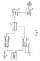
- FIG. 1 A system for processing a video signal is shown in Figure 1.
- An input video signal is manipulated so that an output image, produced on displaying an output video signal, appears to take the shape of a three dimensional object.
- a conventional video image may, for example, be placed around a globe or a cylinder etc.
- a video input signal is supplied to a frame store 20 via an input line 21, an address generator 22 and an attenuator 23.
- a coarse three dimensional address map is stored in the address store which is supplied to the write address generator 22.
- Generator 22 includes a spacial interpolator, a temporal interpolator, means for converting the three dimensional addresses to two dimensions and means for addressing four frame store locations for each input pixel.
- the system therefore performs "write side" processing as described in United Kingdom Patent Application Nos. 2119594A and 2158671A each assigned to the assignee of the present application. Pixels are read from the frame store 20 in standard raster format by a read address generator 24 to produce an output video signal on a line 25; the processing being performed in real time at the video rate.
- each pixel is attenuated by attenuator 23 in response to light intensity factors which simulate the effect of shading on a three dimensional object.
- the light intensity factors are calculated by a processing device 26 in response to the coarse address map and information relating to an imaginary light source, supplied on a line 27.
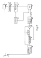
- the processing device 26 is shown in detail in Figure 2. Address signals, representing a coarse map, are supplied to an arithmetic processor 40 so that groups of three signals, two from one line and one from the next, are available at the same time. These lines will of course not coincide with adjacent video lines.
- Arithmetic processor 40 therefore calculates the vector normal to the surface containing the three points (x1, y1, z1), (x2, y2, z2,), (x3, y3, z3). This vector is defined by the cross product of the three points i.e.
- processor 41 calculates thenormalisation factors for the two vectors N and S .
- the normalisation factor for a vector is given by one over the square root of x squared plus y squared plus Z squared, as shown at the output of processor 41. As the numbers involved may be quite large processor 41 also performs a conversion to floating point arithmetic.
- the normalised vectors N and S are generated in a multiplier 42 by multipling each component of the two vectors by the normalisation factor calculated in processor 41.
- add and multiply circuit 43 which produces an output cosine for each surface.
- the processing of the address signals is of course continuous so that the output from circuit 43 will be the cosine A for each surface of the shape defined by the coarse map.
- Kd cos A + Ks cos n B Values for the term (Kd cos A + Ks cos n B) for different values of A are available in a look up table in RAM 44 with Kd, Ks and n being independently variable and provided empirically for different values of A to give the best results in the output image.
- the RAM 44 may be loaded with values from a computer 45.
- the first term in the equation IaKa takes into account the intensity of the ambient lighting and the reflectivity of the surface.
- the values for this term, and also source intensity and distance from the point source to the surface, can be chosen by the operator using the computer 45.
- K is a constant for all shapes.
- the processor 46 is simply a multiplier which multiplies the above term from RAM 44 (Kd cos A etc) by a factor relating to the point source intensity and the factor 1/(r + K).
- Kd and Ks are chosen so that the term from RAM 44 is between 0 & 1.
- the calculated light intensities for the point in a coarse map are supplied to an interpolator 47 which interpolates these intensity factors to produce one for each point in the manipulated image. It is to be understood that the processing of the address maps to produce intensity factors is done in real time.
- the incoming video signals are manipulted in real time to produce an output image of a different shape.
- the video signals can also be attenuated by amounts relating to shading of the shape due to a point light source so that the shape can be seen more easily.
- the calculation of the light intensity factor is not limited to the model used here. Also several point sources may be used and the effect of coloured sources can also be simulated. If coloured sources are used some of the factors in the equation will be colour dependent.
Landscapes
- Engineering & Computer Science (AREA)
- Multimedia (AREA)
- Signal Processing (AREA)
- Computer Graphics (AREA)
- Physics & Mathematics (AREA)
- General Physics & Mathematics (AREA)
- Theoretical Computer Science (AREA)
- Image Generation (AREA)
- Processing Or Creating Images (AREA)
- Studio Circuits (AREA)
- Controls And Circuits For Display Device (AREA)
Description
- The present invention relates to a video signal processing system for changing the shape of a video image so that a video frame appears to take the form of a three dimensional object.
- Systems of this type are disclosed in our United Kingdom Patent application Nos. GB-A-2119594 and GB-A-2158671. These known systems receive video signals, at video rate, representing sequences of images which are manipulated to produce images of a different shape to the input image. The type of processing used to produce this manipulation is called write side interpolation in which incoming picture point signals are written into addresses in a framestore, determined by the shape of the final image, and read out in normal raster format. The write addresses are pre-calculated and provide a coarse map of addresses for, say, every fourth pixel in every fourth line of every fourth field. These coarse maps can themselves be manipulated to produce a change in position or orientation in space.
- As input video signals are received by the system the coarse maps are interpolated to provide the intervening addresses. In practice the write addresses do not generally fall on framestore addresses so one incoming picture point signal makes contributions to the nearest framestore addresses to the write address provided. The video signals are also interpolated and written into the desired addresses. When the contents of the framestore are read out in normal raster format the video images appear at video rate as before but the shape of the image has been changed.
- Although the shape manipulation of this system is effective there is no allowance for shading from different light sources and some details of the shape may be lost particularly where there is a lot of detail in the video. It is therefore an object of the present invention to provide a system for providing shape manipulation which is capable of producing the
- COMPUTER VISION GRAPHICS AND IMAGE PROCESSING, volume 29 number 3, March 1985, pages 361-367, Academic Press Inc., New York, U.S.; D. Gordon et al: "Image Space Shading of 3-dimensional objects", teaches generally the shoding of an object defined in terams of planar polygons using the normal to each polygon. It also discusses one solution to the problem of shading an object defined only in terms of point addresses, as in the maps described above. However, it does not suggest the approach of viewing such an object as made up of surfaces formed by three adjacent coordinates.
- According to the present invention there is provided a video signal processing system for changing the shape of a video image so that a video frame appears to take the form of a three dimensional object, the system comprising:
- a) an address storage device for storing an address map defining the shape of said three dimensional object;
- b) a frame store;
- c) means for loading pixels of an input frame into the frame store in a first sequence; and
- d) means for reading said pixels out of said frame store in a second sequence wherein the relationship between said first sequence and said second sequence is determined from the address map; as is known for example from our abovementioned patent application number GB-A-2,158,671 the present invention being characterised by:
- e) a processing device for processing the address data in combination with an indication of the position of an imaginary light source to produce light intensity factors; and
- f) means for adjusting the value of each pixel in the video frame in response to a light intensity factor to produce a video frame having shading due to the imaginary light source; and in that the address map representing the three dimensional object consists of a plurality of point co-ordinates, and the processing device includes means for calculating a light intensity factor for each surface defined by three adjacent co-ordinates.
- In a preferred embodiment the processing device includes means for calculating the angle between a vector which is perpendicular to a surface of the three dimensional object and a vector from said surface to said light source, and means for producing a light intensity factor relating to said angle.
- Preferably the value of each pixel is adjusted in response to a light intensity factor before said pixel is loaded into the frame store.
- The invention will now be described, by way of example only, with respect to the drawings of which:
- Figure 1 shows a video processing device for manipulating the shape of a video image including a processing device for applying shading to the image.
- Figure 2 details the processing device shown in Figure 1, and
- Figure 3 illustrates the vectors involved in the calculation of the reflected light intensity.
- A system for processing a video signal is shown in Figure 1. An input video signal is manipulated so that an output image, produced on displaying an output video signal, appears to take the shape of a three dimensional object. Thus a conventional video image may, for example, be placed around a globe or a cylinder etc.
- A video input signal is supplied to a
frame store 20 via aninput line 21, anaddress generator 22 and anattenuator 23. A coarse three dimensional address map is stored in the address store which is supplied to thewrite address generator 22.Generator 22 includes a spacial interpolator, a temporal interpolator, means for converting the three dimensional addresses to two dimensions and means for addressing four frame store locations for each input pixel. The system therefore performs "write side" processing as described in United Kingdom Patent Application Nos. 2119594A and 2158671A each assigned to the assignee of the present application. Pixels are read from theframe store 20 in standard raster format by aread address generator 24 to produce an output video signal on aline 25; the processing being performed in real time at the video rate. - Before being loaded into the
frame store 20 each pixel is attenuated byattenuator 23 in response to light intensity factors which simulate the effect of shading on a three dimensional object. The light intensity factors are calculated by aprocessing device 26 in response to the coarse address map and information relating to an imaginary light source, supplied on aline 27. - The
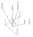
processing device 26 is shown in detail in Figure 2. Address signals, representing a coarse map, are supplied to anarithmetic processor 40 so that groups of three signals, two from one line and one from the next, are available at the same time. These lines will of course not coincide with adjacent video lines. - In the model used in this embodiment the intensity of the reflected light from a surface is dependent on the angle A between a vector perpendicular (or normal) to the surface of the object and the vector from the light source to said surface (see Fig. 3).
Arithmetic processor 40 therefore calculates the vector normal to the surface containing the three points (x₁, y₁, z₁), (x₂, y₂, z₂,), (x₃, y₃, z₃). This vector is defined by the cross product of the three points i.e. XN = (x₁ x₂ - x₂ x₃), YN = (y₁ y₂ - y₂ y₃), ZN = (z₁ z₂ - z₂ z₃) and is calculated using multiplication and subtraction circuits in known manner. Once the co-ordinates of the normal have been calculated as above so that N = XN i + YN j + ZN k then with the position of the light source known (the vector from the source being S = Xs i + Ys j + Zs k) it is relatively easy to calculate the cosine of the angle A. The dot product N S = NS cos A so if N and S are normalised N S = cos A. After the normal vector has been calculated inarithmetic processor 40 the signals are passed to processor 41 which calculates thenormalisation factors for the two vectors N and S. The normalisation factor for a vector is given by one over the square root of x squared plus y squared plus Z squared, as shown at the output of processor 41. As the numbers involved may be quite large processor 41 also performs a conversion to floating point arithmetic. The normalised vectors N and S are generated in amultiplier 42 by multipling each component of the two vectors by the normalisation factor calculated in processor 41. The final stage in determining cos. A is to form the dot product of the two vectors N.S = xNxS + yNyS + zNzS where
- This is done in add and
multiply circuit 43 which produces an output cosine for each surface. The processing of the address signals is of course continuous so that the output fromcircuit 43 will be the cosine A for each surface of the shape defined by the coarse map. - The reflected light intensity from a surface is given in this model by:

- Where
Ia = ambient light intensity
Ka = reflection coefficient
Ip = point source intensity
r = distance from the source to the surface
Kd = diffuse reflectivity
Ks = specular reflection
B is the angle between the reflection vector and the vector from the viewer
k is a constant - The cosnB term relates to the angle between the viewer and the direction of reflected light from the surface. Calculation may be simplified if it is assumed that the postion of the viewer and the light source are co-incident, in which case B = 2A. Once the cos A term is obtained in add and multiply
circuit 43 it is supplied to RAM 44 which provides a look up table for arc-cos A. - Values for the term (Kd cos A + Ks cos nB) for different values of A are available in a look up table in
RAM 44 with Kd, Ks and n being independently variable and provided empirically for different values of A to give the best results in the output image. TheRAM 44 may be loaded with values from acomputer 45. - The first term in the equation IaKa takes into account the intensity of the ambient lighting and the reflectivity of the surface. The values for this term, and also source intensity and distance from the point source to the surface, can be chosen by the operator using the
computer 45. K is a constant for all shapes. Once the term (Kd cos A + Ks cosn B) is available from theRAM 44 then it is supplied to aprocessor 46 to evaluate the reflected light intensity for the chosen values for IaKa, r and Ip. In this embodiment the processor is simply a multiplier which multiplies the above term from RAM 44 (Kd cos A etc) by a factor relating to the point source intensity and thefactor 1/(r + K). Kd and Ks are chosen so that the term fromRAM 44 is between 0 & 1. - The calculated light intensities for the point in a coarse map are supplied to an
interpolator 47 which interpolates these intensity factors to produce one for each point in the manipulated image. It is to be understood that the processing of the address maps to produce intensity factors is done in real time. - In this embodiment the incoming video signals are manipulted in real time to produce an output image of a different shape. The video signals can also be attenuated by amounts relating to shading of the shape due to a point light source so that the shape can be seen more easily.
- It is to be understood that the calculation of the light intensity factor is not limited to the model used here. Also several point sources may be used and the effect of coloured sources can also be simulated. If coloured sources are used some of the factors in the equation will be colour dependent.
Claims (9)
Applications Claiming Priority (2)
| Application Number | Priority Date | Filing Date | Title |
|---|---|---|---|
| GB868613447A GB8613447D0 (en) | 1986-06-03 | 1986-06-03 | Video image processing systems |
| GB8613447 | 1986-06-03 |
Publications (3)
| Publication Number | Publication Date |
|---|---|
| EP0248626A2 EP0248626A2 (en) | 1987-12-09 |
| EP0248626A3 EP0248626A3 (en) | 1988-09-07 |
| EP0248626B1 true EP0248626B1 (en) | 1991-10-16 |
Family
ID=10598858
Family Applications (1)
| Application Number | Title | Priority Date | Filing Date |
|---|---|---|---|
| EP87304838A Expired - Lifetime EP0248626B1 (en) | 1986-06-03 | 1987-06-01 | Video signal processing |
Country Status (5)
| Country | Link |
|---|---|
| US (1) | US4899295A (en) |
| EP (1) | EP0248626B1 (en) |
| JP (1) | JPS6324289A (en) |
| DE (1) | DE3773747D1 (en) |
| GB (1) | GB8613447D0 (en) |
Families Citing this family (16)
| Publication number | Priority date | Publication date | Assignee | Title |
|---|---|---|---|---|
| JPH07121084B2 (en) * | 1987-11-06 | 1995-12-20 | 日本電気株式会社 | Television video signal special effect device |
| GB8728836D0 (en) * | 1987-12-10 | 1988-01-27 | Quantel Ltd | Electronic image processing |
| US5369737A (en) * | 1988-03-21 | 1994-11-29 | Digital Equipment Corporation | Normalization of vectors associated with a display pixels of computer generated images |
| US5255352A (en) * | 1989-08-03 | 1993-10-19 | Computer Design, Inc. | Mapping of two-dimensional surface detail on three-dimensional surfaces |
| EP0449478A3 (en) * | 1990-03-29 | 1992-11-25 | Microtime Inc. | 3d video special effects system |
| US5095204A (en) * | 1990-08-30 | 1992-03-10 | Ball Corporation | Machine vision inspection system and method for transparent containers |
| EP0498625B1 (en) * | 1991-02-08 | 1995-12-20 | The Grass Valley Group, Inc. | Television special effects generator with progressive scanning and corresponding method |
| JP2959249B2 (en) * | 1991-11-15 | 1999-10-06 | ソニー株式会社 | Video effect device |
| JP3102031B2 (en) * | 1992-03-31 | 2000-10-23 | セイコーエプソン株式会社 | 3D color image generation system and method using simulated light source |
| GB2267007B (en) * | 1992-04-24 | 1995-09-13 | Sony Broadcast & Communication | Video special effect apparatus and method |
| EP0574111B1 (en) * | 1992-04-24 | 1997-10-01 | Sony United Kingdom Limited | Lighting effects for digital video effects system |
| JP3107452B2 (en) * | 1992-04-28 | 2000-11-06 | 株式会社日立製作所 | Texture mapping method and apparatus |
| US5974189A (en) * | 1993-05-24 | 1999-10-26 | Eastman Kodak Company | Method and apparatus for modifying electronic image data |
| US5764871A (en) * | 1993-10-21 | 1998-06-09 | Eastman Kodak Company | Method and apparatus for constructing intermediate images for a depth image from stereo images using velocity vector fields |
| US5900881A (en) * | 1995-03-22 | 1999-05-04 | Ikedo; Tsuneo | Computer graphics circuit |
| US7616198B2 (en) * | 1998-02-20 | 2009-11-10 | Mental Images Gmbh | System and computer-implemented method for modeling the three-dimensional shape of an object by shading of a two-dimensional image of the object |
Citations (2)
| Publication number | Priority date | Publication date | Assignee | Title |
|---|---|---|---|---|
| GB2119594A (en) * | 1982-03-19 | 1983-11-16 | Quantel Ltd | Video processing systems |
| GB2158671A (en) * | 1984-04-19 | 1985-11-13 | Quantel Ltd | Improvements in or relating to video signal processing systems |
Family Cites Families (10)
| Publication number | Priority date | Publication date | Assignee | Title |
|---|---|---|---|---|
| US4609917A (en) * | 1983-01-17 | 1986-09-02 | Lexidata Corporation | Three-dimensional display system |
| US4682160A (en) * | 1983-07-25 | 1987-07-21 | Harris Corporation | Real time perspective display employing digital map generator |
| US4700181A (en) * | 1983-09-30 | 1987-10-13 | Computer Graphics Laboratories, Inc. | Graphics display system |
| US4586038A (en) * | 1983-12-12 | 1986-04-29 | General Electric Company | True-perspective texture/shading processor |
| JPH0746391B2 (en) * | 1984-09-14 | 1995-05-17 | 株式会社日立製作所 | Graphic seeding device |
| US4727364A (en) * | 1984-09-19 | 1988-02-23 | Mcdonnell Douglas Corporation | Method and apparatus for intensity shading in a visual display |
| JP2526857B2 (en) * | 1984-12-27 | 1996-08-21 | ソニー株式会社 | Image signal conversion method |
| JPH0681275B2 (en) * | 1985-04-03 | 1994-10-12 | ソニー株式会社 | Image converter |
| EP0205252B1 (en) * | 1985-05-08 | 1989-09-13 | Sony Corporation | Video signal processing |
| US4737921A (en) * | 1985-06-03 | 1988-04-12 | Dynamic Digital Displays, Inc. | Three dimensional medical image display system |
-
1986
- 1986-06-03 GB GB868613447A patent/GB8613447D0/en active Pending
-
1987
- 1987-05-20 US US07/052,464 patent/US4899295A/en not_active Expired - Lifetime
- 1987-05-27 JP JP62128561A patent/JPS6324289A/en active Granted
- 1987-06-01 DE DE8787304838T patent/DE3773747D1/en not_active Expired - Lifetime
- 1987-06-01 EP EP87304838A patent/EP0248626B1/en not_active Expired - Lifetime
Patent Citations (2)
| Publication number | Priority date | Publication date | Assignee | Title |
|---|---|---|---|---|
| GB2119594A (en) * | 1982-03-19 | 1983-11-16 | Quantel Ltd | Video processing systems |
| GB2158671A (en) * | 1984-04-19 | 1985-11-13 | Quantel Ltd | Improvements in or relating to video signal processing systems |
Also Published As
| Publication number | Publication date |
|---|---|
| US4899295A (en) | 1990-02-06 |
| JPH0434159B2 (en) | 1992-06-05 |
| GB8613447D0 (en) | 1986-07-09 |
| EP0248626A3 (en) | 1988-09-07 |
| JPS6324289A (en) | 1988-02-01 |
| DE3773747D1 (en) | 1991-11-21 |
| EP0248626A2 (en) | 1987-12-09 |
Similar Documents
| Publication | Publication Date | Title |
|---|---|---|
| US4590465A (en) | Graphics display system using logic-enhanced pixel memory cells | |
| EP0637813B1 (en) | Image processing | |
| EP0248626B1 (en) | Video signal processing | |
| US4714428A (en) | Method of comprehensive distortion correction for a computer image generation system | |
| EP0221704B1 (en) | Video signal processing | |
| JP2550530B2 (en) | Video signal processing method | |
| US4811245A (en) | Method of edge smoothing for a computer image generation system | |
| US5461706A (en) | Lighting effects for digital video effects system | |
| US5659671A (en) | Method and apparatus for shading graphical images in a data processing system | |
| EP0300703B1 (en) | Depth buffer priority processing for real time computer image generating systems | |
| US4862388A (en) | Dynamic comprehensive distortion correction in a real time imaging system | |
| US4343037A (en) | Visual display systems of the computer generated image type | |
| US4985854A (en) | Method for rapid generation of photo-realistic imagery | |
| US5704024A (en) | Method and an apparatus for generating reflection vectors which can be unnormalized and for using these reflection vectors to index locations on an environment map | |
| US3816726A (en) | Computer graphics clipping system for polygons | |
| CA2301607C (en) | An improved method and apparatus for per pixel mip mapping and trilinear filtering | |
| EP0449478A2 (en) | 3D video special effects system | |
| EP0837429B1 (en) | Apparatus and method for simulating specular reflection in a computer graphics/imaging system | |
| US5923331A (en) | Method of generation of computer-generated images using a spherical buffer | |
| US6552726B2 (en) | System and method for fast phong shading | |
| GB2266425A (en) | Lighting effects for digital video effects system | |
| EP0656609B1 (en) | Image processing | |
| KR100429092B1 (en) | Graphic image processing method and apparatus | |
| EP0250588B1 (en) | Comprehensive distortion correction in a real time imaging system | |
| US5821942A (en) | Ray tracing through an ordered array |
Legal Events
| Date | Code | Title | Description |
|---|---|---|---|
| PUAI | Public reference made under article 153(3) epc to a published international application that has entered the european phase |
Free format text: ORIGINAL CODE: 0009012 |
|
| AK | Designated contracting states |
Kind code of ref document: A2 Designated state(s): DE FR GB IT |
|
| PUAL | Search report despatched |
Free format text: ORIGINAL CODE: 0009013 |
|
| AK | Designated contracting states |
Kind code of ref document: A3 Designated state(s): DE FR GB IT |
|
| 17P | Request for examination filed |
Effective date: 19881025 |
|
| 17Q | First examination report despatched |
Effective date: 19891106 |
|
| GRAA | (expected) grant |
Free format text: ORIGINAL CODE: 0009210 |
|
| AK | Designated contracting states |
Kind code of ref document: B1 Designated state(s): DE FR GB IT |
|
| REF | Corresponds to: |
Ref document number: 3773747 Country of ref document: DE Date of ref document: 19911121 |
|
| ET | Fr: translation filed | ||
| ITF | It: translation for a ep patent filed |
Owner name: DR. ING. A. RACHELI & C. |
|
| PLBE | No opposition filed within time limit |
Free format text: ORIGINAL CODE: 0009261 |
|
| STAA | Information on the status of an ep patent application or granted ep patent |
Free format text: STATUS: NO OPPOSITION FILED WITHIN TIME LIMIT |
|
| 26N | No opposition filed | ||
| PGFP | Annual fee paid to national office [announced via postgrant information from national office to epo] |
Ref country code: GB Payment date: 19990526 Year of fee payment: 13 |
|
| PGFP | Annual fee paid to national office [announced via postgrant information from national office to epo] |
Ref country code: DE Payment date: 19990607 Year of fee payment: 13 |
|
| PGFP | Annual fee paid to national office [announced via postgrant information from national office to epo] |
Ref country code: FR Payment date: 19990610 Year of fee payment: 13 |
|
| PG25 | Lapsed in a contracting state [announced via postgrant information from national office to epo] |
Ref country code: GB Free format text: LAPSE BECAUSE OF NON-PAYMENT OF DUE FEES Effective date: 20000601 |
|
| GBPC | Gb: european patent ceased through non-payment of renewal fee |
Effective date: 20000601 |
|
| PG25 | Lapsed in a contracting state [announced via postgrant information from national office to epo] |
Ref country code: FR Free format text: LAPSE BECAUSE OF NON-PAYMENT OF DUE FEES Effective date: 20010228 |
|
| REG | Reference to a national code |
Ref country code: FR Ref legal event code: ST |
|
| PG25 | Lapsed in a contracting state [announced via postgrant information from national office to epo] |
Ref country code: DE Free format text: LAPSE BECAUSE OF NON-PAYMENT OF DUE FEES Effective date: 20010403 |
|
| PG25 | Lapsed in a contracting state [announced via postgrant information from national office to epo] |
Ref country code: IT Free format text: LAPSE BECAUSE OF NON-PAYMENT OF DUE FEES;WARNING: LAPSES OF ITALIAN PATENTS WITH EFFECTIVE DATE BEFORE 2007 MAY HAVE OCCURRED AT ANY TIME BEFORE 2007. THE CORRECT EFFECTIVE DATE MAY BE DIFFERENT FROM THE ONE RECORDED. Effective date: 20050601 |