EP0247902A2 - Motorcycle with fairing - Google Patents
Motorcycle with fairing Download PDFInfo
- Publication number
- EP0247902A2 EP0247902A2 EP87304819A EP87304819A EP0247902A2 EP 0247902 A2 EP0247902 A2 EP 0247902A2 EP 87304819 A EP87304819 A EP 87304819A EP 87304819 A EP87304819 A EP 87304819A EP 0247902 A2 EP0247902 A2 EP 0247902A2
- Authority
- EP
- European Patent Office
- Prior art keywords
- fairing
- motorcycle
- head pipe
- frame assembly
- main frames
- Prior art date
- Legal status (The legal status is an assumption and is not a legal conclusion. Google has not performed a legal analysis and makes no representation as to the accuracy of the status listed.)
- Granted
Links
Images

Classifications
-
- B—PERFORMING OPERATIONS; TRANSPORTING
- B62—LAND VEHICLES FOR TRAVELLING OTHERWISE THAN ON RAILS
- B62J—CYCLE SADDLES OR SEATS; AUXILIARY DEVICES OR ACCESSORIES SPECIALLY ADAPTED TO CYCLES AND NOT OTHERWISE PROVIDED FOR, e.g. ARTICLE CARRIERS OR CYCLE PROTECTORS
- B62J17/00—Weather guards for riders; Fairings or stream-lining parts not otherwise provided for
Definitions
- the present invention relates to a motorcycle and more particularly to a motorcycle having a fairing covering front and side portions of the motorcycle for protecting a 'motorcycle frame and an engine and reducing air resistance produced while the motorcycle is running.
- the disclosed fairing covers a front area of the handlebar and extends around the head lamp and along opposite sides of the engine.
- the fairing has a ram air inlet opening defined in its front panel for introducing ram air toward the engine.
- Ram air inlet and outlet ports are also defined in lateral side walls or panels of the fairing for cooling the engine with high efficiency. Ram-air is drawn through the ram air inlet ports to cool the engine, and ram air heated by the radiator is discharged through the ram air outlet ports outwardly and rearwardly of the fairing.
- the fairing comprises a plurality of separate fairing members of suitable shapes formed of synthetic resin by injection molding and interconnected by screws.
- the disclosed fairing assembly comprises a fairing of synthetic resin covering a front area of the handlebar and extending around the head lamp and along opposite sides of the engine, and a pair of laterally spaced side covers disposed behind the fairing and covering an area below the rider's seat.
- the side covers have front ends bent outwardly and joined to the rear end of the fairing.
- Ram air which has been heated by cooling the engine flows from within the fairing and inside of the side covers and is discharged rearwardly of the motorcycle without touching the feet of the rider sitting on the seat.
- the known fairings have upper free ends which are not joined to the motorcycle frame.
- the fairings which are made of synthetic resin in view of appearance and cost produce considerable noise while the motorcycle is running because the fairings tend to vibrate in resonance with ram air or engine vibration. Vibration of the fairings which takes place at all times while the motorcycle is running is not preferable from the standpoint of durability.
- the present invention provides a motorcycle comprising:
- the invention provides a motorcycle comprising:
- a motorcycle 1 with a fairing has a frame assembly generally designated by the reference numeral 3.
- the frame assembly 3 comprises a head pipe 5, a pair of laterally spaced, substantially J-shaped main frames 7 of an aluminum alloy inclined downwardly and extending rearwardly from the head pipe 5 and having rear portions 7a directed downwardly, and a pair of laterally spaced engine hangers 9 (only one shown) depending from front portions of the main frames 7 and cooperating with the main frames 7 in supporting an engine 10 with support shafts 11, 12, 13.
- a front fork 15 on which a front wheel 17 is rotatably supported is steerably supported on the head pipe 5, with a handlebar 19 attached to the top of the front fork 15.
- a rear fork 21 having a substantially H shape as viewed in plan with a rear wheel 25 being rotatably supported on the opposite ends of the rear fork 21.
- Two laterally spaced rear frames 27 are detachably coupled to rear portions of the main frames 7, and a rider's seat or saddle 29 is supported on the rear frames 27.
- a fairing assembly 30 installed on the frame assembly 3 comprises a front fairing 32 extending rearwardly from a position in front of the handlebar 19 in covering relation to the head pipe 5 on opposite sides thereof and having an opening 34 (FIG. 1) in which a head lamp 36 is mounted, and a pair of side fairings 40 joined to the front fairing 32 by suitable means and covering opposite lateral sides of a front motorcycle portion including an engine 10, a radiator 42, and the frame assembly 3.
- the fairings 32, 40 are. preferably formed of synthetic resin by injection molding.
- the side fairings 40 have a pair of side walls or panels 50 having respective recesses 52 defined in lower portions thereof and reinforcing flanges 54 extending inwardly and by which the side walls 50 are reinforced, respectively.
- the side fairings 40 also have steps 56 extending inwardly from upper ends of the side walls 50, respectively, and upstanding portions 58 extending upwardly from the steps 56, respectively.
- the upstanding portions 58 have attachment holes 60 defined in distal ends thereof.
- Each of the upstanding portions has one or more headed pins 62 (FIG. 5) integrally formed with its inner side wall surface.
- Reinforcing flanges 64 project horizontally inwardly from longitudinal edges of the upstanding portions 58, and have apertured brackets 66 on their rear ends.
- Interior inspection covers 70 are removably attached to front portions of the respective side walls 50.
- the covers 70 and the steps 56 have vent holes 72, 74, respectively, defined therein. Heated air that has passed through the radiator 42 is discharged out through the vent holes 72, 74.
- a fuel tank 80 comprises an outer panel 82 having flanges 82a on opposite edges thereof and an inner or bottom panel 84 having flanges 84a on opposite edges thereof, the flanges 82a, 84a being joined to each other by suitable means such as seam welding.
- the joined flanges have three brackets 86, 87, 88 with bolt holes.
- each of the main frames 7 is of a rectangular cross section and has a ladder-shaped internal structure.
- the front end portion of each of the main frames 7 has a bolt hole 94 for attachment of the corresponding side fairing, and the curved portion of each main frame 7 has a bracket 96 projecting therefrom and having a bolt hole.
- rubber grommets 98 as the number of headed pins 62 on the side fairings 40 are disposed on the outer side surfaces of the main frames 7.
- the upstanding portions 58 of the side fairings 40 are brought closely to the outer sides of the main frames 7 with the flanges 64 near the upper surfaces of the main frames 7. Then, the headed pins 62 are fitted into the respective grommets 98, and the attachment holes 60 of the upstanding portions 58 at the upper or free ends of the side fairings 40 and the bolt holes of the brackets 66 are registered with the bolt holes 94 of the main frames 7 and the bolt holes of the brackets 96. Finally, bolts 100, 102 are passed through the aligned bolt holes to fasten the side fairings 40 to the main frames 7. Since the upper ends of the side fairings 40 are secured to the main frames 7, any vibration of the fairing 30 which may be produced while the motorcycle is running can be suppressed.
- the joined flanges 82a, 84a on the lower end of the fuel tank 80 are located in the vicinity of the distal edges of the reinforcing flanges 64 of the upstanding portions 58. Therefore, the assembled structure has a neat appearance.
- side covers 104 may be disposed adjacent to and behind the side fairings 40.
- the side covers 104 have fixing portions 106, respectively, on their distal lower ends.
- the fixing portions 106 are of a substantially C-shaped cross section and have respective bolt holes 108.
- FIG. 6 shows only one side cover 104 and associated components.
- the brackets 66 of the upstanding portions 58 of the side fairings 40 are brought into registry with the respective brackets 96 of the main frames 7, with spacers 110 intersposed between the registered brackets 66, 96.
- the fixing portions 106 of the side covers 104 are placed on the brackets 66, respectively.
- Bolts 102 are inserted through the bolt holes from outside, and thereafter nuts 112 are threaded over the inner ends of the bolts 102. 1
- the fairing is not adversely affected by ram air or engine vibration, and noise is considerably reduced, while the motor cycle is running.
- the present invention provides a motorcycle with a fairing which is prevented from vibrating and.has an increased degree of durability; and furthermore provides a motorcycle with a fairing and side covers which can easily be installed on a motorcycle frame and joined to each other.
Landscapes
- Engineering & Computer Science (AREA)
- Mechanical Engineering (AREA)
- Automatic Cycles, And Cycles In General (AREA)
Abstract
Description
- The present invention relates to a motorcycle and more particularly to a motorcycle having a fairing covering front and side portions of the motorcycle for protecting a 'motorcycle frame and an engine and reducing air resistance produced while the motorcycle is running.
- One typical motorcycle fairing is disclosed in Japanese Laid-Open Patent Publication No. 60/67280. The disclosed fairing covers a front area of the handlebar and extends around the head lamp and along opposite sides of the engine. The fairing has a ram air inlet opening defined in its front panel for introducing ram air toward the engine. Ram air inlet and outlet ports are also defined in lateral side walls or panels of the fairing for cooling the engine with high efficiency. Ram-air is drawn through the ram air inlet ports to cool the engine, and ram air heated by the radiator is discharged through the ram air outlet ports outwardly and rearwardly of the fairing. The fairing comprises a plurality of separate fairing members of suitable shapes formed of synthetic resin by injection molding and interconnected by screws.
- Another motorcycle fairing assembly disclosed in Japanese Laid-Open Patent Publication No. 60/146771 discharges ram air that has cooled the engine from a rear portion of the motorcycle on which the fairing assembly is mounted. The disclosed fairing assembly comprises a fairing of synthetic resin covering a front area of the handlebar and extending around the head lamp and along opposite sides of the engine, and a pair of laterally spaced side covers disposed behind the fairing and covering an area below the rider's seat. The side covers have front ends bent outwardly and joined to the rear end of the fairing. Ram air which has been heated by cooling the engine flows from within the fairing and inside of the side covers and is discharged rearwardly of the motorcycle without touching the feet of the rider sitting on the seat.
- The known fairings have upper free ends which are not joined to the motorcycle frame. The fairings which are made of synthetic resin in view of appearance and cost produce considerable noise while the motorcycle is running because the fairings tend to vibrate in resonance with ram air or engine vibration. Vibration of the fairings which takes place at all times while the motorcycle is running is not preferable from the standpoint of durability.
- With the motorcycle fairing assembly disclosed in Japanese Laid-Open Patent Publication No. 60/146771, it is necessary to fasten the fairing and the side covers to the motorcycle frame, and then to join the fairing and the side covers. However, the process of fastening and joining the fairing and the side covers is tedious and time-consuming, and the number of joint parts is large.
- Viewed from one aspect the present invention provides a motorcycle comprising:
- a frame assembly including a head pipe on which a front fork is steerably supported, a pair of laterally spaced main frames extending rearwardly from said head pipe, and a rear fork swingably coupled to said main frames;
- a front wheel rotatably supported on said front fork;
- a rear wheel rotatably supported on said rear fork;
- an engine supported on said frame assembly; and
- a fairing extending rearwardly from a position in front of said head pipe in covering relation to part of said engine and said frame assembly
- said fairing assembly having an upper end fastened to said main frames.
- Viewed from another aspect the invention provides a motorcycle comprising:
- a frame assembly including a head pipe and a pair of laterally spaced main frame members extending rearwardly from said head pipe;
- an engine supported on said frame assembly; and
- a fairing extending rearwardly from a position in front of said head pipe in covering relation to part of said engine and said frame assembly;
- an upper part-of said fairing being fastened to said main frame members.
- An embodiment of the invention will now be described by way of example and with reference to the accompanying drawings, in which:-
- FIG. 1 is a side elevational view of a motorcycle with a fairing according to the present invention;
- FIG. 2 is a side elevational view of the motorcycle of FIG. 1 with a fairing and side covers omitted from illustration for clearly showing a frame-structure;
- FIG. 3 is a rear elevational view of the motorcycle shown in FIG. 1;
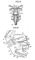
- FIG. 4 is an enlarged perspective view of the fairing illustrated in FIG. 1;
- FIG. 5 is a cross-sectional view taken along line V - Vof FIG. 4; and
- FIG. 6 is an enlarged cross-sectional view taken along line VI - VI of FIG. 1.
- As shown in FIGS. 1 through 3, a motorcycle 1 with a fairing according a preferred embodiment of the present invention has a frame assembly generally designated by the
reference numeral 3. Theframe assembly 3 comprises a head pipe 5, a pair of laterally spaced, substantially J-shapedmain frames 7 of an aluminum alloy inclined downwardly and extending rearwardly from the head pipe 5 and having rear portions 7a directed downwardly, and a pair of laterally spaced engine hangers 9 (only one shown) depending from front portions of themain frames 7 and cooperating with themain frames 7 in supporting anengine 10 withsupport shafts 11, 12, 13. Afront fork 15 on which a front wheel 17 is rotatably supported is steerably supported on the head pipe 5, with ahandlebar 19 attached to the top of thefront fork 15. To the downwardly extending rear portions 7a of themain frames 7, there are swingably attached two spaced ends of arear fork 21 having a substantially H shape as viewed in plan with arear wheel 25 being rotatably supported on the opposite ends of therear fork 21. Two laterally spacedrear frames 27 are detachably coupled to rear portions of themain frames 7, and a rider's seat orsaddle 29 is supported on therear frames 27. - As shown in FIGS. 4 and 5, a
fairing assembly 30 installed on theframe assembly 3 comprises afront fairing 32 extending rearwardly from a position in front of thehandlebar 19 in covering relation to the head pipe 5 on opposite sides thereof and having an opening 34 (FIG. 1) in which ahead lamp 36 is mounted, and a pair ofside fairings 40 joined to thefront fairing 32 by suitable means and covering opposite lateral sides of a front motorcycle portion including anengine 10, aradiator 42, and theframe assembly 3. Thefairings - The
side fairings 40 have a pair of side walls orpanels 50 havingrespective recesses 52 defined in lower portions thereof and reinforcingflanges 54 extending inwardly and by which theside walls 50 are reinforced, respectively. Theside fairings 40 also have steps 56 extending inwardly from upper ends of theside walls 50, respectively, andupstanding portions 58 extending upwardly from thesteps 56, respectively. Theupstanding portions 58 haveattachment holes 60 defined in distal ends thereof. Each of the upstanding portions has one or more headed pins 62 (FIG. 5) integrally formed with its inner side wall surface. Reinforcingflanges 64 project horizontally inwardly from longitudinal edges of theupstanding portions 58, and have aperturedbrackets 66 on their rear ends. Interior inspection covers 70 are removably attached to front portions of therespective side walls 50. Thecovers 70 and thesteps 56 havevent holes radiator 42 is discharged out through thevent holes - In FIGS. 4 and 5, a
fuel tank 80 comprises anouter panel 82 having flanges 82a on opposite edges thereof and an inner orbottom panel 84 having flanges 84a on opposite edges thereof, the flanges 82a, 84a being joined to each other by suitable means such as seam welding. The joined flanges have threebrackets fuel tank 80 on themotorcycle frame assembly 3, bolt holes (not shown) defined in therear frames 27 and attachment members 90 (only one shown), 92 disposed between therear frames 27 are brought into registry with the thread holes of thebrackets - As illustrated in FIG. 5, each of the
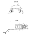
main frames 7 is of a rectangular cross section and has a ladder-shaped internal structure. As shown in FIG. 2, the front end portion of each of themain frames 7 has abolt hole 94 for attachment of the corresponding side fairing, and the curved portion of eachmain frame 7 has abracket 96 projecting therefrom and having a bolt hole. As many rubber grommets 98 as the number of headedpins 62 on theside fairings 40 are disposed on the outer side surfaces of themain frames 7. - For installing the
side fairings 40 on themain frames 7, theupstanding portions 58 of theside fairings 40 are brought closely to the outer sides of themain frames 7 with theflanges 64 near the upper surfaces of themain frames 7. Then, theheaded pins 62 are fitted into therespective grommets 98, and theattachment holes 60 of theupstanding portions 58 at the upper or free ends of theside fairings 40 and the bolt holes of thebrackets 66 are registered with thebolt holes 94 of themain frames 7 and the bolt holes of thebrackets 96. Finally,bolts side fairings 40 to themain frames 7. Since the upper ends of theside fairings 40 are secured to themain frames 7, any vibration of thefairing 30 which may be produced while the motorcycle is running can be suppressed. - The joined flanges 82a, 84a on the lower end of the
fuel tank 80 are located in the vicinity of the distal edges of the reinforcingflanges 64 of theupstanding portions 58. Therefore, the assembled structure has a neat appearance. - As shown in FIG. 6,
side covers 104 may be disposed adjacent to and behind theside fairings 40. The side covers 104 have fixingportions 106, respectively, on their distal lower ends. The fixingportions 106 are of a substantially C-shaped cross section and have respective bolt holes 108. - Attachment of the side covers 104 to the
main frames 7 and theside fairings 40 will be described with reference to FIG. 6 which shows only oneside cover 104 and associated components. Thebrackets 66 of theupstanding portions 58 of theside fairings 40 are brought into registry with therespective brackets 96 of themain frames 7, withspacers 110 intersposed between the registeredbrackets portions 106 of the side covers 104 are placed on thebrackets 66, respectively.Bolts 102 are inserted through the bolt holes from outside, and thereafter nuts 112 are threaded over the inner ends of thebolts 102. 1 - As so arranged, the fairing is not adversely affected by ram air or engine vibration, and noise is considerably reduced, while the motor cycle is running.
- It will thus be seen that the present invention, at least in its preferred forms, provides a motorcycle with a fairing which is prevented from vibrating and.has an increased degree of durability; and furthermore provides a motorcycle with a fairing and side covers which can easily be installed on a motorcycle frame and joined to each other.
- It is to be clearly understood that there are no particular features of the foregoing specification, or of any claims appended hereto, which are at present regarded as being essential to the performance of the present invention, and that any one or more of such features or combinations thereof may therefore be included in, added to, omitted from or deleted from any of such claims if and when amended during the prosecution of this application or in the filing or prosecution of any divisional application based theron.
Claims (9)
Applications Claiming Priority (4)
| Application Number | Priority Date | Filing Date | Title |
|---|---|---|---|
| JP61123654A JPS62283081A (en) | 1986-05-30 | 1986-05-30 | Fairing device for motorcycle |
| JP123654/86 | 1986-05-30 | ||
| JP97070/86 | 1986-06-25 | ||
| JP1986097070U JPH0326064Y2 (en) | 1986-06-25 | 1986-06-25 |
Publications (3)
| Publication Number | Publication Date |
|---|---|
| EP0247902A2 true EP0247902A2 (en) | 1987-12-02 |
| EP0247902A3 EP0247902A3 (en) | 1988-07-20 |
| EP0247902B1 EP0247902B1 (en) | 1991-03-06 |
Family
ID=26438275
Family Applications (1)
| Application Number | Title | Priority Date | Filing Date |
|---|---|---|---|
| EP87304819A Expired - Lifetime EP0247902B1 (en) | 1986-05-30 | 1987-06-01 | Motorcycle with fairing |
Country Status (3)
| Country | Link |
|---|---|
| US (1) | US4776422A (en) |
| EP (1) | EP0247902B1 (en) |
| DE (1) | DE3768334D1 (en) |
Cited By (4)
| Publication number | Priority date | Publication date | Assignee | Title |
|---|---|---|---|---|
| EP1580107A1 (en) * | 2004-03-23 | 2005-09-28 | HONDA MOTOR CO., Ltd. | Vehicle frame structure |
| CN1861470B (en) * | 2005-05-11 | 2011-08-31 | 雅马哈发动机株式会社 | Straddle-type vehicle |
| ES2465742R1 (en) * | 2012-03-22 | 2014-12-09 | Honda Motor Co., Ltd. | WINDOW STRUCTURE FOR MOTORCYCLE TYPE VEHICLE |
| USD1010518S1 (en) * | 2018-07-30 | 2024-01-09 | Harley-Davidson Motor Company, Inc. | Motorcycle fairing |
Families Citing this family (16)
| Publication number | Priority date | Publication date | Assignee | Title |
|---|---|---|---|---|
| JPH0615358B2 (en) * | 1987-10-28 | 1994-03-02 | 本田技研工業株式会社 | Motorcycle front fork |
| USD382835S (en) * | 1993-02-05 | 1997-08-26 | Bayerische Motoren Werke Ag | Motorcycle body |
| JPH0995279A (en) * | 1995-09-29 | 1997-04-08 | Honda Motor Co Ltd | Car body frame for motorcycle |
| US6263994B1 (en) | 1997-10-03 | 2001-07-24 | Frederick G. Eitel | Advanced motorcycle chassis steering and suspension system |
| US6238017B1 (en) | 1997-10-03 | 2001-05-29 | Frederick G. Eitel | Advanced motorcycle chassis and braking system |
| US6588529B2 (en) * | 2000-07-05 | 2003-07-08 | Yamaha Hatsudoki Kabishuki Kaisha | Body cover and structure for motorcycle |
| CA2532069A1 (en) * | 2003-07-10 | 2005-01-27 | Rick Michael Salisbury | Modular and detachable fairing for a motorcycle |
| DE602005018027D1 (en) * | 2004-03-10 | 2010-01-14 | George Metzikis | PROTECTIVE COVER FOR A MOTORCYCLE |
| US20050212252A1 (en) * | 2004-03-29 | 2005-09-29 | Michael Czysz | Single-bolt clipon for motorcycle |
| JP2007008442A (en) * | 2005-03-11 | 2007-01-18 | Yamaha Motor Co Ltd | Motorcycle exhaust system |
| JP2008222079A (en) * | 2007-03-13 | 2008-09-25 | Yamaha Motor Co Ltd | Motorcycle |
| JP5112092B2 (en) * | 2008-01-31 | 2013-01-09 | 本田技研工業株式会社 | Rear frame mounting structure for motorcycles |
| JP5156507B2 (en) * | 2008-07-04 | 2013-03-06 | 川崎重工業株式会社 | Leg shield for vehicles |
| JP5486978B2 (en) * | 2010-03-25 | 2014-05-07 | 本田技研工業株式会社 | Motorcycle cowl structure |
| JP6058957B2 (en) * | 2012-09-21 | 2017-01-11 | 本田技研工業株式会社 | Side cover structure for saddle-ride type vehicles |
| ES2800071B2 (en) * | 2019-06-21 | 2021-06-23 | Univ Huelva | SYSTEM FOR ANCHORING THE FAIRING TO THE CHASSIS OF A MOTORCYCLE |
Citations (4)
| Publication number | Priority date | Publication date | Assignee | Title |
|---|---|---|---|---|
| GB657203A (en) * | 1948-02-03 | 1951-09-12 | Guiseppe Remondini | Improvements in motor cycles |
| US4413700A (en) * | 1980-09-17 | 1983-11-08 | Honda Giken Kogyo Kabushiki Kaisha | Seat mounting structure for motorcycles and associated methods |
| FR2550751A1 (en) * | 1983-08-18 | 1985-02-22 | Honda Motor Co Ltd | MATERIAL FOR THE MANUFACTURE OF FRAMES OF MOTOR VEHICLES AND FRAME STRUCTURE MANUFACTURED USING THE MATERIAL |
| US4633965A (en) * | 1983-09-06 | 1987-01-06 | Honda Giken Kogyo Kabushiki Kaisha | Motorcycle |
Family Cites Families (9)
| Publication number | Priority date | Publication date | Assignee | Title |
|---|---|---|---|---|
| US1430938A (en) * | 1922-05-03 | 1922-10-03 | Calvignac Germain | Pressed-steel frame for motor cycles and like vehicles |
| US3154342A (en) * | 1962-12-28 | 1964-10-27 | Eckhoff And Slick | Motorcycle fairing |
| US4461508A (en) * | 1981-05-18 | 1984-07-24 | Honda Giken Kogyo Kabushiki Kaisha | Fairing assembly for motorcycles |
| JPS604029A (en) * | 1983-06-23 | 1985-01-10 | Morito Kk | Method of expressing pattern on surface of fixing member made of synthetic resin |
| JPS6067280A (en) * | 1983-09-26 | 1985-04-17 | ヤマハ発動機株式会社 | Cowling device for motorcycle |
| JPS60146771A (en) * | 1984-01-10 | 1985-08-02 | スズキ株式会社 | Frame cover for motorcycle |
| JPS6159187U (en) * | 1984-09-14 | 1986-04-21 | ||
| JPH0211266Y2 (en) * | 1984-12-26 | 1990-03-20 | ||
| US4678054A (en) * | 1984-12-26 | 1987-07-07 | Honda Giken Kogyo Kabushiki Kaisha | Body frames |
-
1987
- 1987-05-29 US US07/055,462 patent/US4776422A/en not_active Expired - Fee Related
- 1987-06-01 DE DE8787304819T patent/DE3768334D1/en not_active Expired - Fee Related
- 1987-06-01 EP EP87304819A patent/EP0247902B1/en not_active Expired - Lifetime
Patent Citations (4)
| Publication number | Priority date | Publication date | Assignee | Title |
|---|---|---|---|---|
| GB657203A (en) * | 1948-02-03 | 1951-09-12 | Guiseppe Remondini | Improvements in motor cycles |
| US4413700A (en) * | 1980-09-17 | 1983-11-08 | Honda Giken Kogyo Kabushiki Kaisha | Seat mounting structure for motorcycles and associated methods |
| FR2550751A1 (en) * | 1983-08-18 | 1985-02-22 | Honda Motor Co Ltd | MATERIAL FOR THE MANUFACTURE OF FRAMES OF MOTOR VEHICLES AND FRAME STRUCTURE MANUFACTURED USING THE MATERIAL |
| US4633965A (en) * | 1983-09-06 | 1987-01-06 | Honda Giken Kogyo Kabushiki Kaisha | Motorcycle |
Cited By (5)
| Publication number | Priority date | Publication date | Assignee | Title |
|---|---|---|---|---|
| EP1580107A1 (en) * | 2004-03-23 | 2005-09-28 | HONDA MOTOR CO., Ltd. | Vehicle frame structure |
| US7195263B2 (en) | 2004-03-23 | 2007-03-27 | Honda Motor Co., Ltd. | Vehicle frame structure |
| CN1861470B (en) * | 2005-05-11 | 2011-08-31 | 雅马哈发动机株式会社 | Straddle-type vehicle |
| ES2465742R1 (en) * | 2012-03-22 | 2014-12-09 | Honda Motor Co., Ltd. | WINDOW STRUCTURE FOR MOTORCYCLE TYPE VEHICLE |
| USD1010518S1 (en) * | 2018-07-30 | 2024-01-09 | Harley-Davidson Motor Company, Inc. | Motorcycle fairing |
Also Published As
| Publication number | Publication date |
|---|---|
| EP0247902B1 (en) | 1991-03-06 |
| US4776422A (en) | 1988-10-11 |
| EP0247902A3 (en) | 1988-07-20 |
| DE3768334D1 (en) | 1991-04-11 |
Similar Documents
| Publication | Publication Date | Title |
|---|---|---|
| EP0247902A2 (en) | Motorcycle with fairing | |
| JP4527148B2 (en) | Motorcycle | |
| US4715465A (en) | Body construction for motor scooter vehicles | |
| JP5944228B2 (en) | Saddle riding | |
| EP2703272B1 (en) | Storage part structure for saddle type vehicle | |
| US6478105B2 (en) | Air cleaner fitting structure for motorcycle | |
| JP5871671B2 (en) | Suction type vehicle intake structure | |
| EP1063160B1 (en) | Motorcycle | |
| JP2009161017A (en) | Motorcycle | |
| EP2017168B1 (en) | Straddle type vehicle | |
| JP2002284072A (en) | Heat shielding structure of fuel tank for scooter type vehicle | |
| JP3584720B2 (en) | Motorcycle | |
| JP2009202803A (en) | Front cowl and wind screen fitting structure of motorcycle | |
| EP2077221A2 (en) | Straddle-type vehicle | |
| EP0602591A1 (en) | Air cleaner for motor-bicycle | |
| JP4720482B2 (en) | Motorcycle frame cover | |
| JP4299099B2 (en) | Scooter type front cover structure | |
| US20190248436A1 (en) | Saddle riding vehicle | |
| US20220315154A1 (en) | Saddle-ride vehicle | |
| JP3406159B2 (en) | Body cover structure of motorcycle | |
| JP5460885B2 (en) | Front structure of motorcycle | |
| EP1873047B1 (en) | Footboard structure for vehicle | |
| JP2687126B2 (en) | Pillion frame structure for motorcycles | |
| JP2015047959A (en) | Fuel tank mounting structure of saddle-riding type vehicle | |
| JPS59118529A (en) | Radiator for bicycle |
Legal Events
| Date | Code | Title | Description |
|---|---|---|---|
| PUAI | Public reference made under article 153(3) epc to a published international application that has entered the european phase |
Free format text: ORIGINAL CODE: 0009012 |
|
| AK | Designated contracting states |
Kind code of ref document: A2 Designated state(s): DE FR GB IT |
|
| PUAL | Search report despatched |
Free format text: ORIGINAL CODE: 0009013 |
|
| AK | Designated contracting states |
Kind code of ref document: A3 Designated state(s): DE FR GB IT |
|
| 17P | Request for examination filed |
Effective date: 19880916 |
|
| 17Q | First examination report despatched |
Effective date: 19891109 |
|
| GRAA | (expected) grant |
Free format text: ORIGINAL CODE: 0009210 |
|
| AK | Designated contracting states |
Kind code of ref document: B1 Designated state(s): DE FR GB IT |
|
| REF | Corresponds to: |
Ref document number: 3768334 Country of ref document: DE Date of ref document: 19910411 |
|
| ET | Fr: translation filed | ||
| PGFP | Annual fee paid to national office [announced via postgrant information from national office to epo] |
Ref country code: GB Payment date: 19910524 Year of fee payment: 5 |
|
| ITF | It: translation for a ep patent filed |
Owner name: SOCIETA' ITALIANA BREVETTI S.P.A. |
|
| PGFP | Annual fee paid to national office [announced via postgrant information from national office to epo] |
Ref country code: FR Payment date: 19910529 Year of fee payment: 5 |
|
| PGFP | Annual fee paid to national office [announced via postgrant information from national office to epo] |
Ref country code: DE Payment date: 19910607 Year of fee payment: 5 |
|
| PLBE | No opposition filed within time limit |
Free format text: ORIGINAL CODE: 0009261 |
|
| STAA | Information on the status of an ep patent application or granted ep patent |
Free format text: STATUS: NO OPPOSITION FILED WITHIN TIME LIMIT |
|
| 26N | No opposition filed | ||
| PG25 | Lapsed in a contracting state [announced via postgrant information from national office to epo] |
Ref country code: GB Effective date: 19920601 |
|
| GBPC | Gb: european patent ceased through non-payment of renewal fee |
Effective date: 19920601 |
|
| PG25 | Lapsed in a contracting state [announced via postgrant information from national office to epo] |
Ref country code: FR Effective date: 19930226 |
|
| PG25 | Lapsed in a contracting state [announced via postgrant information from national office to epo] |
Ref country code: DE Effective date: 19930302 |
|
| REG | Reference to a national code |
Ref country code: FR Ref legal event code: ST |
|
| PG25 | Lapsed in a contracting state [announced via postgrant information from national office to epo] |
Ref country code: IT Free format text: LAPSE BECAUSE OF NON-PAYMENT OF DUE FEES;WARNING: LAPSES OF ITALIAN PATENTS WITH EFFECTIVE DATE BEFORE 2007 MAY HAVE OCCURRED AT ANY TIME BEFORE 2007. THE CORRECT EFFECTIVE DATE MAY BE DIFFERENT FROM THE ONE RECORDED. Effective date: 20050601 |