EP0247693A2 - Heating device for deicing railway switches - Google Patents
Heating device for deicing railway switches Download PDFInfo
- Publication number
- EP0247693A2 EP0247693A2 EP87200966A EP87200966A EP0247693A2 EP 0247693 A2 EP0247693 A2 EP 0247693A2 EP 87200966 A EP87200966 A EP 87200966A EP 87200966 A EP87200966 A EP 87200966A EP 0247693 A2 EP0247693 A2 EP 0247693A2
- Authority
- EP
- European Patent Office
- Prior art keywords
- radiators
- heating
- heating system
- heated
- switches
- Prior art date
- Legal status (The legal status is an assumption and is not a legal conclusion. Google has not performed a legal analysis and makes no representation as to the accuracy of the status listed.)
- Withdrawn
Links
Images

Classifications
-
- E—FIXED CONSTRUCTIONS
- E01—CONSTRUCTION OF ROADS, RAILWAYS, OR BRIDGES
- E01B—PERMANENT WAY; PERMANENT-WAY TOOLS; MACHINES FOR MAKING RAILWAYS OF ALL KINDS
- E01B7/00—Switches; Crossings
- E01B7/24—Heating of switches
Definitions
- the present invention relates to a heating system for de-icing train switches using a warm liquid for heat conduction and distribution.
- the object of the present invention is to eliminate the above-mentioned deficiencies, whereby a heating system is to be proposed which operates with a minimum amount of energy, distributes the heat evenly over the parts of the switch to be de-iced and ensures an almost constant supply of heat.
- a heating system for de-icing train switches characterized by a heat source removed from the switches, radiators which are arranged in the area of the switch parts, and pipes which connect the heat source and the radiators in such a way that they form a closed circuit.
- the invention provides that the heat is transported and distributed via a liquid heated outside the effective range of the deicing.
- a liquid is capable of absorbing a significant amount of energy at a low temperature, ensuring that the heat input is relatively constant for all parts to be de-iced.
- the heating system regulates itself thanks to the minimal temperature difference required for heat conduction. A part that is only a few degrees colder than another part will therefore automatically absorb a considerably larger amount of heat.
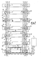
- the heating system consists of a heat group l that heats the heat-conducting liquid, of a circuit formed by pipes 2 for conducting and distributing the heating liquid, and of radiators 3, 4, 5 that transfer the heat to the parts of the switch to be de-iced.
- the direction of flow of the liquid is indicated by arrows.
- the parts to be heated are preferably the fixed rails 6 and the movable cast steel supports 7 for the movable sections of the rails 8.
- the tie rods 9 of the switch can also be heated.
- the points to be heated can be connected in series or in parallel.
- a mixed circuit is shown in FIG.
- the heat group l can be fed by various types of energy sources, e.g. B. it can be operated by means of electrical resistors, gas burners or liquid fuel burners, etc.
- the heat group has a structure which is known per se and is provided with all those components which are necessary for the operation of a heating circuit, such as, for example, circulation pumps, Heaters, thermostats, etc. It is obvious that the hot liquid could also be supplied by a heat group that feeds several switches.
- the heat transfer from the circuit to the part of the switch to be heated mainly takes place via the metallic contact between the parts.
- the corresponding heating element 3 has the shape of a preferably flat tube which is fastened to the rail by means of a bracket 10 or by soldering or the like.
- the radiators 3 are provided with an insulating shield 11 on the outer surface in order to limit energy losses.
- the radiator 3 contains the flow pipe and the return pipe at the same time. In this way, the radiators for the supports 7 can be connected in parallel via connection pieces schematically indicated by l2.
- the radiators 4 have a comb-like shape corresponding to the standardized base of the carrier.
- the circuit is made by inserting the radiator on each side into the gap between the upper and lower plates of the support base 7 with a connector l3.
- FIG. 4 shows a variant for heating the carrier 7.
- the liquid circuit is established by the gap between the upper and lower plate of the carrier 7 with the introduction and welding of sheets 14 and the formation of openings 15 is tightly closed in the ribs.
- the heating system according to the invention is also capable of heating other components of the switch.
- the heating or defrosting of a pull rod 9 by means of a tubular heating element is provided in FIG.
Landscapes
- Engineering & Computer Science (AREA)
- Mechanical Engineering (AREA)
- Architecture (AREA)
- Civil Engineering (AREA)
- Structural Engineering (AREA)
- Air-Conditioning For Vehicles (AREA)
- Central Heating Systems (AREA)
Abstract
Description
Die vorliegende Erfindung betrifft eine Heizanlage zur Enteisung von Zugweichen unter Verwendung einer Warmflüssigkeit zur Wärmeleitung und -verteilung.The present invention relates to a heating system for de-icing train switches using a warm liquid for heat conduction and distribution.
Bei bekannten Heizsystemen zur Enteisung von Zugweichen werden entweder elektrische Widerstände oder Gasbrenner verwendet, die jedenfalls die Wärme mehr oder weniger direkt den zu enteisenden Weichenteilen zuführen. Diese Heizsysteme sehen keine Wärmespeicherung vor und verursachen eine ungleichmäßige Wärmeverteilung, und zwar überhitzte Stellen und solche mit ungenügender Temperatur. In den bekannten Heizsystemen muß überdies die Höhe der Heiztemperatur verhältnismäßig groß sein, was im allgemeinen zu einer Energieverschwendung führt.In known heating systems for de-icing train switches, either electrical resistors or gas burners are used, which in any case supply the heat more or less directly to the switch parts to be de-iced. These heating systems do not provide heat storage and cause an uneven heat distribution, namely overheated places and those with insufficient temperature. In the known heating systems, moreover, the level of the heating temperature must be relatively high, which generally leads to a waste of energy.
Es liegt nahe, daß bei den bekannten Heizsystemen auch Temperaturfühler und Stellglieder verwendet werden könnten. Es wäre jedoch sehr schwierig für die vorgesehene Anwendung Reguliersysteme auszuführen, die genügend zuverläßlich wären.It is obvious that temperature sensors and actuators could also be used in the known heating systems. However, it would be very difficult for the intended application to implement regulating systems that would be sufficiently reliable.
Die Aufgabe der vorliegenden Erfindung liegt in der Beseitigung der oben angegebenen Mängel, wobei eine Heizanlage vorgeschlagen werden soll, die mit einem Mindestmaß an Energieaufwand arbeitet, die Wärme gleichmäßig auf die zu enteisenden Weichenteile verteilt und eine nahezu konstante Wärmezufuhr gewährleistet.The object of the present invention is to eliminate the above-mentioned deficiencies, whereby a heating system is to be proposed which operates with a minimum amount of energy, distributes the heat evenly over the parts of the switch to be de-iced and ensures an almost constant supply of heat.
Diese Aufgabe wird erfindungsgemäß durch eine Heizanlage zur Enteisung von Zugweichen gelöst, gekennzeichnet durch eine von den Weichen entfernte Wärmequelle, Heizkörper, die im Bereich der Weichenteile angeordnet sind, und Rohrleitungen, die die Wärmequelle und die Heizkörper derart miteinander verbinden, daß dieselben einen geschlossenen Kreislauf bilden.This object is achieved by a heating system for de-icing train switches, characterized by a heat source removed from the switches, radiators which are arranged in the area of the switch parts, and pipes which connect the heat source and the radiators in such a way that they form a closed circuit.
Die Erfindung sieht vor, daß die Wärme über eine außerhalb des Wirkungsbereiches der Enteisung erwärmte Flüssigkeit transportiert und verteilt wird. Eine Flüssigkeit ist fähig,eine erhebliche Energiemenge bei einer niedrigen Temperaturhöhe aufzunehmen, wobei sichergestellt wird, daß die Wärmezufuhr verhältnismäßig konstant für alle zu enteisenden Teile erfolgt. Bis zu einem gewissen Punkt regelt sich die Heizanlage von selbst, dank der minimalen Temperaturdifferenz, die für die Wärmeleitung erforderlich ist. Ein nur wenige Grade gegenüber einem anderen Teil kälterer Teil wird daher selbsttätig eine erheblich größere Wärmemenge aufnehmen.The invention provides that the heat is transported and distributed via a liquid heated outside the effective range of the deicing. A liquid is capable of absorbing a significant amount of energy at a low temperature, ensuring that the heat input is relatively constant for all parts to be de-iced. Up to a point, the heating system regulates itself thanks to the minimal temperature difference required for heat conduction. A part that is only a few degrees colder than another part will therefore automatically absorb a considerably larger amount of heat.
Dank der niedrigen Höhe der Temperatur können wirtschaftliche Energiequellen, wie Wärmepumpen, Abwässer u.s.w. verwendet werden.Thanks to the low temperature, economic energy sources such as heat pumps, waste water, etc. be used.
Weitere Merkmale, Einzelheiten und Vorteile der vorliegenden Erfindung gehen aus der folgenden Beschreibung ihrer Ausführungsformen unter Bezugnahme auf die beigelegten Zeichnungen hervor. In den Zeichnungen zeigen:
- Figur l eine Draufsicht einer erfindungsgemäßen Heizanlage bei Anwendung an eine einfache Weiche mit elastischem Scharnier;
- Figur 2 einen Schnitt, gemäß der Linie II-II aus Figur l, durch eine Schiene bzw. einen Träger mit einem auf beiden angebrachten Heizkörper gemäß der Erfindung;
Figur 3 einen Schnitt gemäß der Linie III-III aus Figur 2;Figur 4 einen Schnitt durch eine Variante des Trägers.
- Figure l is a plan view of a heating system according to the invention when used on a simple switch with elastic Hinge;
- Figure 2 shows a section, along the line II-II of Figure 1, through a rail or a support with a radiator attached to both according to the invention;
- Figure 3 shows a section along the line III-III of Figure 2;
- Figure 4 shows a section through a variant of the carrier.
Wie in den Zeichnungen dargestellt, besteht die erfindungsgemäße Heizanlage aus einer die wärmeleitende Flüßigkeit erhitzende Wärmegruppe l, aus einem durch Rohre 2 zur Leitung und Verteilung der Heizflüssigkeit gebildeten Kreislauf und aus Heizkörpern 3,4,5, die die Wärme den zu enteisenden Weichenteilen übertragen. Die Flußrichtung der Flüssigkeit ist durch Pfeile angegeben. Die zu erwärmenden Teile sind vorzugsweise die festen Gleise 6 und die beweglichen aus Stahlguß bestehenden Träger 7 für die beweglichen Abschnitte der Gleise 8. Überdies können auch die Zugstangen 9 der Weiche erhitzt werden.As shown in the drawings, the heating system according to the invention consists of a heat group l that heats the heat-conducting liquid, of a circuit formed by pipes 2 for conducting and distributing the heating liquid, and of
Die zu erwärmenden Stellen können in Serie oder parallel geschaltet sein. In Figur l ist eine gemischte Schaltung dargestellt.The points to be heated can be connected in series or in parallel. A mixed circuit is shown in FIG.
Die Wärmegruppe l kann durch verschiedenartige Energiequellen gespeist werden, z. B. kann sie mittels elektrischen Widerständen, Gasbrennern oder Flüssigbrennstoffbrennern usw. betrieben werden. Die Wärmegruppe besitzt einen für sich bekannten Aufbau und ist mit allen jenen Bestandteilen versehen, die für den Betrieb eines Heizkreislaufes erforderlich sind, wie z.B. Umlaufpumpen, Erhitzern, Thermostaten, usw.. Es liegt nahe, daß die Warmflüssigkeit auch von einer Wärmegruppe geliefert werden könnte, die mehrere Weichen speist. Die Wärmeübertragung vom Kreislauf auf den zu erwärmenden Teil der Weiche erfolgt vorwiegend über die metallische Berührung zwischen den Teilen. Für die festen Schienen 6 besitzt der entsprechende Heizkörper 3 die Form eines vorzugsweise flachen Rohres, das an der Schiene mittels eines Bügels l0 oder durch Verlöten o. ä. befestigt ist.The heat group l can be fed by various types of energy sources, e.g. B. it can be operated by means of electrical resistors, gas burners or liquid fuel burners, etc. The heat group has a structure which is known per se and is provided with all those components which are necessary for the operation of a heating circuit, such as, for example, circulation pumps, Heaters, thermostats, etc. It is obvious that the hot liquid could also be supplied by a heat group that feeds several switches. The heat transfer from the circuit to the part of the switch to be heated mainly takes place via the metallic contact between the parts. For the
Wie aus Figur 2 ersichtlich, sind die Heizkörper 3 zur Begrenzung von Energieverlusten mit einer isolierenden Abschirmung ll auf der Außenfläche versehen. Der Heizkörper 3 enthält gleichzeitig das Vorlauf- und das Rücklaufrohr. Auf diese Weise können die Heizkörper für die Träger 7 über mit l2 schematisch angedeuteten Ansschlußstücke parallel geschalten werden.As can be seen from FIG. 2, the
Wie in Figur 3 dargestellt, besitzen die Heizköper 4 eine der standardisierten Basis des Trägers entsprechende, kammartige Form. Der Kreislauf wird hergestellt, indem der Heizkörper auf jeder Seite in die Lücke zwischen der oberen und der unteren Platte der Trägerbasis 7 mit einem Verbindungsstück l3 eingefügt wird.As shown in Figure 3, the
In Figur 4 ist eine Variante zur Erwärmung des Trägers 7 dargestellt. In diesem Fall wird der Flüssigkeitskreislauf hergestellt, indem die Lücke zwischen der oberen und unteren Platte des Trägers 7 unter Einbringung und Verschweißung von Blechen l4 und Ausarbeitung von Durchbrüchen l5 in den Rippen dicht geschlossen wird. Bei dieser Lösung kommt die Warmflüssigkeit direkt mit dem Körper des Trägers in Berührung, wodurch eine sehr wirksamer thermischer Austausch sichergestellt wird.FIG. 4 shows a variant for heating the
Es ist klar, daß die oben beschriebene, dichte Abschließung beim Gießen des Trägers unter Einbringung eines Kerns verwirklicht werden kann. Außer der festen Schiene 6 und den Trägern 7 ist die erfindungsgemäße Heizanlage auch fähig, andere Bestandteile der Weiche zu erwärmen. So ist beispielsweise in Figur l die Erwärmung bzw. Enteisung einer Zugstange 9 mittels eines rohrförmigen Heizkörpers vorgesehen.It is clear that the tight seal described above can be achieved when the carrier is cast by inserting a core. In addition to the
Claims (5)
Applications Claiming Priority (2)
| Application Number | Priority Date | Filing Date | Title |
|---|---|---|---|
| IT482386 | 1986-05-27 | ||
| IT8604823A IT8604823A0 (en) | 1986-05-27 | 1986-05-27 | HEATING SYSTEM FOR THE THAWING OF RAILWAY POINTS BY CONDUCTING HEAT THROUGH HOT LIQUID. |
Publications (2)
| Publication Number | Publication Date |
|---|---|
| EP0247693A2 true EP0247693A2 (en) | 1987-12-02 |
| EP0247693A3 EP0247693A3 (en) | 1988-06-08 |
Family
ID=11114389
Family Applications (1)
| Application Number | Title | Priority Date | Filing Date |
|---|---|---|---|
| EP87200966A Withdrawn EP0247693A3 (en) | 1986-05-27 | 1987-05-21 | Heating device for deicing railway switches |
Country Status (2)
| Country | Link |
|---|---|
| EP (1) | EP0247693A3 (en) |
| IT (1) | IT8604823A0 (en) |
Cited By (15)
| Publication number | Priority date | Publication date | Assignee | Title |
|---|---|---|---|---|
| EP1262597A2 (en) * | 2001-06-01 | 2002-12-04 | Holland Railconsult B.V. | Method and system for heating of rail and railelement for use therewith |
| GB2417508A (en) * | 2004-08-24 | 2006-03-01 | Schwihag Gmbh | Fastening device for fixing a stock rail in a set of railway points |
| WO2009109664A1 (en) | 2008-03-07 | 2009-09-11 | Tripe S Gmbh | Switch heating system |
| EP2182114A3 (en) * | 2008-10-29 | 2010-08-04 | Heatpoint B.V. | Heating for railway switches |
| RU2470108C2 (en) * | 2008-04-25 | 2012-12-20 | Общество с ограниченной ответственностью Научно-производственная фирма "Электроавтоматик" | Device for heating of point switch |
| WO2013037635A1 (en) | 2011-09-13 | 2013-03-21 | Triple S-Gmbh | Switch heating system |
| DE102011119739A1 (en) | 2011-11-30 | 2013-06-06 | Iftec Gmbh & Co.Kg | Rail switch i.e. streetcar rail switch, has heaters comprising connection unit for connecting heating elements, where connection unit is arranged in gussets between stock rail and tongue root and/or tongue connection piece |
| DE202012103258U1 (en) | 2012-08-28 | 2013-12-02 | Triple S-Gmbh | Heat exchanger arrangement for a heating system for heating a rail switch |
| DE202012103257U1 (en) * | 2012-08-28 | 2013-12-02 | Triple S-Gmbh | Heating device for heating a rail foot |
| WO2014032864A1 (en) * | 2012-08-28 | 2014-03-06 | Triple S-Gmbh | Slide chair for a rail switch |
| WO2014041041A1 (en) * | 2012-09-13 | 2014-03-20 | Pintsch Aben geotherm GmbH | Heat exchanger for switches and switch heating system |
| WO2014041042A1 (en) * | 2012-09-13 | 2014-03-20 | Pintsch Aben geotherm GmbH | Heat exchanger for rails and switches and switch heating system |
| DE102012111357A1 (en) * | 2012-11-23 | 2014-05-28 | Schwihag Ag | Slide chair for a rail switch |
| DE102013009269A1 (en) | 2013-06-04 | 2014-12-04 | Iftec Gmbh & Co.Kg | Heatable switch and method for heating a switch |
| DE102013016232A1 (en) * | 2013-10-01 | 2015-04-02 | Ean Elektroschaltanlagen Gmbh | Temperature control unit for track elements and system for controlling the temperature of track elements |
Citations (5)
| Publication number | Priority date | Publication date | Assignee | Title |
|---|---|---|---|---|
| US2704517A (en) * | 1951-08-08 | 1955-03-22 | Gracia Manuel De | Railroad track with rail de-icing means |
| DE1905601A1 (en) * | 1969-02-05 | 1970-08-13 | Viktor Thiel | Thermo-oil hot air heating for track switches |
| DE2042486B1 (en) * | 1970-08-27 | 1971-12-16 | Schreck Mieves Gmbh | TONGUE DEVICE F] R GROOVED RAIL SWITCHES |
| FR2244053A1 (en) * | 1973-09-14 | 1975-04-11 | Stecma | Method of heating railway points - uses electrically heated oil in pipes along the sides of the rails |
| US4429845A (en) * | 1982-04-26 | 1984-02-07 | Emerson Electric Co. | Rail track heaters |
-
1986
- 1986-05-27 IT IT8604823A patent/IT8604823A0/en unknown
-
1987
- 1987-05-21 EP EP87200966A patent/EP0247693A3/en not_active Withdrawn
Patent Citations (5)
| Publication number | Priority date | Publication date | Assignee | Title |
|---|---|---|---|---|
| US2704517A (en) * | 1951-08-08 | 1955-03-22 | Gracia Manuel De | Railroad track with rail de-icing means |
| DE1905601A1 (en) * | 1969-02-05 | 1970-08-13 | Viktor Thiel | Thermo-oil hot air heating for track switches |
| DE2042486B1 (en) * | 1970-08-27 | 1971-12-16 | Schreck Mieves Gmbh | TONGUE DEVICE F] R GROOVED RAIL SWITCHES |
| FR2244053A1 (en) * | 1973-09-14 | 1975-04-11 | Stecma | Method of heating railway points - uses electrically heated oil in pipes along the sides of the rails |
| US4429845A (en) * | 1982-04-26 | 1984-02-07 | Emerson Electric Co. | Rail track heaters |
Non-Patent Citations (1)
| Title |
|---|
| ZEITSCHRIFT F]R EISENBAHNWESEN UND VERKEHRSTECHNIK; GLASERS ANNALEN, Band 96, Nr. 1, Januar 1972, Seiten 18-23; U. FROB\SS: "Die Weichenheizsysteme bei der Deutschen Bundesbahn und ihre w{rmetechnischen Eigenschaften" * |
Cited By (22)
| Publication number | Priority date | Publication date | Assignee | Title |
|---|---|---|---|---|
| NL1018204C2 (en) * | 2001-06-01 | 2002-12-11 | Holland Railconsult B V | Method and system for heating and / or cooling rails and rail element to be used thereby. |
| EP1262597A3 (en) * | 2001-06-01 | 2003-05-07 | Holland Railconsult B.V. | Method and system for heating of rail and railelement for use therewith |
| EP1262597A2 (en) * | 2001-06-01 | 2002-12-04 | Holland Railconsult B.V. | Method and system for heating of rail and railelement for use therewith |
| GB2417508A (en) * | 2004-08-24 | 2006-03-01 | Schwihag Gmbh | Fastening device for fixing a stock rail in a set of railway points |
| GB2417508B (en) * | 2004-08-24 | 2006-07-12 | Schwihag Gmbh | Fastening device for fixing a stock rail in a set of railway points |
| WO2009109664A1 (en) | 2008-03-07 | 2009-09-11 | Tripe S Gmbh | Switch heating system |
| RU2470108C2 (en) * | 2008-04-25 | 2012-12-20 | Общество с ограниченной ответственностью Научно-производственная фирма "Электроавтоматик" | Device for heating of point switch |
| EP2182114A3 (en) * | 2008-10-29 | 2010-08-04 | Heatpoint B.V. | Heating for railway switches |
| EA029004B1 (en) * | 2011-09-13 | 2018-01-31 | Трипл С-Гмбх | Switch heating system |
| WO2013037635A1 (en) | 2011-09-13 | 2013-03-21 | Triple S-Gmbh | Switch heating system |
| DE102011119739A1 (en) | 2011-11-30 | 2013-06-06 | Iftec Gmbh & Co.Kg | Rail switch i.e. streetcar rail switch, has heaters comprising connection unit for connecting heating elements, where connection unit is arranged in gussets between stock rail and tongue root and/or tongue connection piece |
| DE202012103258U1 (en) | 2012-08-28 | 2013-12-02 | Triple S-Gmbh | Heat exchanger arrangement for a heating system for heating a rail switch |
| WO2014032864A1 (en) * | 2012-08-28 | 2014-03-06 | Triple S-Gmbh | Slide chair for a rail switch |
| WO2014032867A2 (en) | 2012-08-28 | 2014-03-06 | Triple S-Gmbh | Heat exchanger arrangement for a heating system for heating a rail switch |
| WO2014032865A3 (en) * | 2012-08-28 | 2014-05-01 | Triple S-Gmbh | Heating device for heating a rail foot |
| DE202012103257U1 (en) * | 2012-08-28 | 2013-12-02 | Triple S-Gmbh | Heating device for heating a rail foot |
| WO2014041041A1 (en) * | 2012-09-13 | 2014-03-20 | Pintsch Aben geotherm GmbH | Heat exchanger for switches and switch heating system |
| WO2014041042A1 (en) * | 2012-09-13 | 2014-03-20 | Pintsch Aben geotherm GmbH | Heat exchanger for rails and switches and switch heating system |
| DE102012111357A1 (en) * | 2012-11-23 | 2014-05-28 | Schwihag Ag | Slide chair for a rail switch |
| DE102013009269A1 (en) | 2013-06-04 | 2014-12-04 | Iftec Gmbh & Co.Kg | Heatable switch and method for heating a switch |
| DE202013012644U1 (en) | 2013-06-04 | 2018-05-15 | Iftec Gmbh & Co.Kg | Heatable switch |
| DE102013016232A1 (en) * | 2013-10-01 | 2015-04-02 | Ean Elektroschaltanlagen Gmbh | Temperature control unit for track elements and system for controlling the temperature of track elements |
Also Published As
| Publication number | Publication date |
|---|---|
| EP0247693A3 (en) | 1988-06-08 |
| IT8604823A0 (en) | 1986-05-27 |
Similar Documents
| Publication | Publication Date | Title |
|---|---|---|
| EP0247693A2 (en) | Heating device for deicing railway switches | |
| DE4433814B4 (en) | motor vehicle | |
| DE2806337C2 (en) | Solar collector system for the direct conversion of the supplied thermal energy into electrical energy | |
| DE7910516U1 (en) | SOLAR BOILER | |
| DE4304532A1 (en) | Method and device for controlling the water supply to a steam generator | |
| DE3433580A1 (en) | METHOD AND DEVICE FOR MELTING PRE-GEL MATERIALS, IN PARTICULAR PHOTOGRAPHIC EMULSIONS | |
| DE2933088C2 (en) | Temperature stabilization for a heat-emitting component of a satellite | |
| DE1811985A1 (en) | Electrically heatable heating plate | |
| DE2712017C3 (en) | Cooling and heating system for a housing equipped with electrical devices | |
| EP1517585B1 (en) | Heating plate | |
| DE1806457C3 (en) | Electric plate heater | |
| EP0279302A1 (en) | Layered heat storer | |
| DE102011075125B4 (en) | Hot water tank with heating element | |
| DE4306790C2 (en) | Natural stone radiant heating | |
| DE3032498A1 (en) | Thermo-electric generator - has certain thermo-couples short circuited to produce maximum temp. gradient | |
| DE4016381C2 (en) | ||
| DE2710139A1 (en) | Domestic water heating system - with low-temp. solar heat collector circuit added to usual heat source | |
| DE2909453A1 (en) | Solar heat collector - with heat storage element in base preventing excessive temp. rise | |
| DE2713014C2 (en) | Device for cooling the supports for the heating material of a heating furnace | |
| EP0305669B1 (en) | Vehicle, especially a coach | |
| DE3149351C2 (en) | Water heater | |
| DE3302324A1 (en) | Heat storage arrangement for buildings, in particular for storing solar energy | |
| DE19719487A1 (en) | Heating system for vehicle | |
| DE2341566B2 (en) | DISCHARGE STATION FOR HOT WATER TANK HEATERS | |
| DE2221742C3 (en) | Track switch heating |
Legal Events
| Date | Code | Title | Description |
|---|---|---|---|
| PUAI | Public reference made under article 153(3) epc to a published international application that has entered the european phase |
Free format text: ORIGINAL CODE: 0009012 |
|
| AK | Designated contracting states |
Kind code of ref document: A2 Designated state(s): AT BE CH DE ES FR GB LI NL SE |
|
| PUAL | Search report despatched |
Free format text: ORIGINAL CODE: 0009013 |
|
| AK | Designated contracting states |
Kind code of ref document: A3 Designated state(s): AT BE CH DE ES FR GB LI NL SE |
|
| STAA | Information on the status of an ep patent application or granted ep patent |
Free format text: STATUS: THE APPLICATION IS DEEMED TO BE WITHDRAWN |
|
| 18D | Application deemed to be withdrawn |
Effective date: 19890418 |