EP0247610B1 - Electromagnetic power generating type rotation sensor - Google Patents
Electromagnetic power generating type rotation sensor Download PDFInfo
- Publication number
- EP0247610B1 EP0247610B1 EP87107751A EP87107751A EP0247610B1 EP 0247610 B1 EP0247610 B1 EP 0247610B1 EP 87107751 A EP87107751 A EP 87107751A EP 87107751 A EP87107751 A EP 87107751A EP 0247610 B1 EP0247610 B1 EP 0247610B1
- Authority
- EP
- European Patent Office
- Prior art keywords
- pole piece
- magnetic pole
- rotation sensor
- power generating
- type rotation
- Prior art date
- Legal status (The legal status is an assumption and is not a legal conclusion. Google has not performed a legal analysis and makes no representation as to the accuracy of the status listed.)
- Expired - Lifetime
Links
Images
Classifications
-
- G—PHYSICS
- G01—MEASURING; TESTING
- G01P—MEASURING LINEAR OR ANGULAR SPEED, ACCELERATION, DECELERATION, OR SHOCK; INDICATING PRESENCE, ABSENCE, OR DIRECTION, OF MOVEMENT
- G01P3/00—Measuring linear or angular speed; Measuring differences of linear or angular speeds
- G01P3/42—Devices characterised by the use of electric or magnetic means
- G01P3/44—Devices characterised by the use of electric or magnetic means for measuring angular speed
- G01P3/48—Devices characterised by the use of electric or magnetic means for measuring angular speed by measuring frequency of generated current or voltage
- G01P3/481—Devices characterised by the use of electric or magnetic means for measuring angular speed by measuring frequency of generated current or voltage of pulse signals
- G01P3/488—Devices characterised by the use of electric or magnetic means for measuring angular speed by measuring frequency of generated current or voltage of pulse signals delivered by variable reluctance detectors
-
- G—PHYSICS
- G01—MEASURING; TESTING
- G01P—MEASURING LINEAR OR ANGULAR SPEED, ACCELERATION, DECELERATION, OR SHOCK; INDICATING PRESENCE, ABSENCE, OR DIRECTION, OF MOVEMENT
- G01P1/00—Details of instruments
- G01P1/02—Housings
- G01P1/026—Housings for speed measuring devices, e.g. pulse generator
Definitions
- the present invention relates to an electromagnetic power generating type rotation sensor for detecting the rotational speed of a rotating member such as the wheel of an automobile.
- an electromagnetic power generating type rotation sensor In general, an electromagnetic power generating type rotation sensor, a magnetic rotation sensor employing a magnetic resistor element or a Hall element and a photoelectric rotation sensor are known as sensors for detecting the rotational speed of a rotating member such as the wheel of an automobile.
- the electromagnetic power generating type rotation sensor is formed by a magnet, a magnetic pole piece and a voltage generating coil integrally contained in a case of metal or resin.
- the amount of magnetic flux in the magnetic pole piece is changed by the irregular surface of a magnetic gear serving as a magnetic rotator in proximity to the magnetic pole piece, thereby to generate AC voltage across a coil.
- the AC voltage thus generated is substantially proportionate to the number of revolutions of the magnetic gear while the frequency thereof is correctly proportionate to the number of revolutions of the magnetic gear, whereby the rotational speed can be detected by the generated AC voltage or the frequency thereof.
- Fig. 3 is a sectional view showing a conventional electromagnetic power generating type rotation sensor.
- numeral 21 indicates the rotation sensor
- numeral 22 indicates a magnet
- numeral 23 indicates a magnetic pole piece
- numeral 24 indicates a coil
- numeral 25 indicates a bobbin
- numeral 26 indicates a case
- numeral 27 indicates an output lead wire
- numeral 28 indicates a bracket of resin for mounting the sensor
- numeral 28a indicates a part filled with resin
- numeral 29 indicates a peripheral part of a magnetic gear.
- the magnetic gear is mounted on a drive shaft of an automobile or the like, to rotate with the wheel of the automobile.
- Magnetic flux of the magnet 2 passes through the magnetic pole piece 23, and the amount of such magnetic flux is changed by approximation to the irregular surface, i.e., projections and recesses of the outer peripheral part 29 of the magnetic rotator.
- output voltage is generated across the coil 24, so that the rotational speed of the magnetic rotator closely related to the rotational speed of the wheel can be detected from the variation in frequency of the output voltage.
- the electromagnetic power generating type rotation sensor is employed for an automobile or the like since the same can be manufactured at a relatively low cost and is resistant against temperature change.
- Such an electromagnetic power generating type rotation sensor employed for an automobile must be excellent in corrosion resistance since the same is mounted on a wheel part in bad environment.
- the magnetic pole piece must be made of an anticorrosive material.
- such a sensor is adapted to detect the rotational speed of the wheel from the change in the amount of magnetic flux in the magnetic pole piece as hereinabove described, and hence the material for the magnetic pole piece must be excellent in magnetic property, i.e., saturation magnetic flux density.
- the material for the magnetic pole piece is excellent in both of magnetic property and corrosion resistance.
- a material of high saturation magnetic flux density is generally inferior in corrosion resistance against rust or the like, whereby no conventional magnetic pole piece has sufficiently satisfied both of the aforementioned conditions.
- an object of the present invention is to provide an electromagnetic power generating type rotation sensor satisfactorily applicable to an automobile, by employing magnetic pole piece which is excellent in both of magnetic property and corrosion resistance.
- magnetic pole piece is divided into an outer magnetic pole piece and an inner magnetic pole piece, such that the outer magnetic pole piece is provided to be opposite to an irregular surface of a magnetic rotator and the inner magnetic pole piece, located adjacent to the outer magnetic pole piece, is inwardly provided not to be exposed to the external environment.
- the irregular surface may be provided either on the outer peripheral part and/or the side part of the magnetic rotator.
- the inner magnetic pole piece is provided in a position not being exposed to the external environment, whereby the same can be prepared by a material of excellent magnetic property with no requirement for corrosion resistance.
- the outer magnetic pole piece can be prepared by a material of excellent corrosion resistance, substantially with no consideration of magnetic property. According to the present invention, the magnetic pole piece is thus divided to be provided with different characteristics which cannot be obtained by a single material.
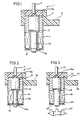
- Fig. 1 is a sectional view showing an embodiment of the present invention.
- an end of an inner magnetic pole piece 3b is mounted on a magnet 2, which is contained in a bobbin 5 with the inner magnetic pole piece 3b.
- An outer magnetic pole piece 3a is closely joined with the other end of the inner magnetic pole piece 3b by welding, to define no clearance.
- the inner magnetic pole piece 3b is made of electromagnetic soft iron, which is inferior in corrosion resistance but excellent in magnetic property, while the outer magnetic pole piece 3a is made of SUS430 (stainless steel material), which is a magnetic substance of excellent corrosion resistance.
- a coil wire is wound around the outer periphery of the bobbin 5 provided with the inner magnetic pole piece 3b, to form a coil 4. Both ends of the coil 4 are connected to an output lead wire 7 respectively, to provide output voltage generated across the coil 4 to the exterior.
- the bobbin 5 and the coil 4 are contained in a case 6, and the outer magnetic pole piece 3a is arranged to partially project from the case 6.
- the outer magnetic pole piece 3a and the case 6 are sealed by welding so that the interior of the case 6 is not exposed to the external environment.
- a cylindrical bracket 8 for mounting the entire sensor is provided in an outer part of the bobbin 5. The interior of the bracket 8 is filled with resin to define a resin-filled part 8a.
- This embodiment of the aforementioned structure can be manufactured through the following steps, for example:
- a cylindrical spacer which is longer than the depth of the case 6, is inserted in the cylindrical case 6, and thereafter the bracket 8 of, e.g., nylon resin is formed by injection molding. Then the spacer is taken out from the case 6, to obtain a cylindrical body formed by the case 6 connected with the bracket 8.
- a sensor element part formed by the magnet 2, the inner magnetic pole piece 3b, the outer magnetic pole piece 3a, the bobbin 5 and the coil 4 and the output lead wire 7 connected thereto are inserted in the cylindrical body. Then the interior of the bracket 8 is filled with resin such as epoxy resin, to define the resin-filled part 8a.
- the inner magnetic pole piece 3b is provided within the case 6 not to be exposed to the external environment as hereinabove described, whereby the inner magnetic pole piece 3b is not corroded by rust or the like even if the same is made of electromagnetic soft iron, which is inferior in corrosion resistance.
- the outer magnetic pole piece 3a exposed to the external environment is made of the stainless steel material of SUS430, which is excellent in corrosion resistance, whereby the same can be employed under bad environment with no corrosion.
- the inner magnetic pole piece 3b and the outer magnetic pole piece 3a are closely joined with each other by welding, thereby to suppress increase in magnetic resistance between the magnetic pole pieces 3a and 3b.
- the inner magnetic pole piece 3b is made of electromagnetic soft iron of excellent magnetic property in the embodiment as. shown in Fig. 1, the material therefor is not restricted to the electromagnetic soft iron, but a material of slightly inferior mechanical strength can also be employed in the present invention so far as the same is excellent in magnetic property.
- the outer magnetic pole piece 3a is made of by the stainless steel material of SUS430 in the aforementioned embodiment, the same can be prepared by other material so far as the material is excellent in corrosion resistance, as a matter of course.
- Fig. 2 is a sectional view showing another embodiment of the present invention.
- an outer magnetic pole piece 13a is larger in diameter than an inner magnetic pole piece 13b.
- Other structure is substantially similar to that of the embodiment as shown in Fig. 1. Namely, a sensor element part formed by a magnet 12, the inner magnetic pole piece 13b, the outer magnetic pole piece 13a, a bobbin 15 and a coil 14 is contained in a case 16 and a bracket 18 and an output lead wire 17 is connected to the sensor element part while a resin-filled part 18a is defined in the bracket 18.
- the outer magnetic pole piece 13a may be made of a material of inferior magnetic property since corrosion resistance is more important. In such case, the outer magnetic pole piece 13a can be made larger in diameter than the inner magnetic pole piece 13b as shown in Fig. 2, to cope with reduction in magnetic property.
Landscapes
- Physics & Mathematics (AREA)
- General Physics & Mathematics (AREA)
- Transmission And Conversion Of Sensor Element Output (AREA)
Description
- The present invention relates to an electromagnetic power generating type rotation sensor for detecting the rotational speed of a rotating member such as the wheel of an automobile.
- In general, an electromagnetic power generating type rotation sensor, a magnetic rotation sensor employing a magnetic resistor element or a Hall element and a photoelectric rotation sensor are known as sensors for detecting the rotational speed of a rotating member such as the wheel of an automobile. The electromagnetic power generating type rotation sensor is formed by a magnet, a magnetic pole piece and a voltage generating coil integrally contained in a case of metal or resin. The amount of magnetic flux in the magnetic pole piece is changed by the irregular surface of a magnetic gear serving as a magnetic rotator in proximity to the magnetic pole piece, thereby to generate AC voltage across a coil. The AC voltage thus generated is substantially proportionate to the number of revolutions of the magnetic gear while the frequency thereof is correctly proportionate to the number of revolutions of the magnetic gear, whereby the rotational speed can be detected by the generated AC voltage or the frequency thereof.
- Fig. 3 is a sectional view showing a conventional electromagnetic power generating type rotation sensor. Referring to Fig. 3,
numeral 21 indicates the rotation sensor,numeral 22 indicates a magnet,numeral 23 indicates a magnetic pole piece,numeral 24 indicates a coil,numeral 25 indicates a bobbin,numeral 26 indicates a case,numeral 27 indicates an output lead wire,numeral 28 indicates a bracket of resin for mounting the sensor, numeral 28a indicates a part filled with resin andnumeral 29 indicates a peripheral part of a magnetic gear. The magnetic gear is mounted on a drive shaft of an automobile or the like, to rotate with the wheel of the automobile. - Magnetic flux of the
magnet 2 passes through themagnetic pole piece 23, and the amount of such magnetic flux is changed by approximation to the irregular surface, i.e., projections and recesses of the outerperipheral part 29 of the magnetic rotator. Depending on the rate of change in the amount of magnetic flux to time, output voltage is generated across thecoil 24, so that the rotational speed of the magnetic rotator closely related to the rotational speed of the wheel can be detected from the variation in frequency of the output voltage. - Detection of the rotational speed of the wheel is important for brake control of the wheel such as antilock control, and hence it is necessary to stably detect the rotational speed of the wheel under various conditions from low-speed to high-speed conditions. The electromagnetic power generating type rotation sensor is employed for an automobile or the like since the same can be manufactured at a relatively low cost and is resistant against temperature change.
- Such an electromagnetic power generating type rotation sensor employed for an automobile must be excellent in corrosion resistance since the same is mounted on a wheel part in bad environment. Thus, the magnetic pole piece must be made of an anticorrosive material. Further, such a sensor is adapted to detect the rotational speed of the wheel from the change in the amount of magnetic flux in the magnetic pole piece as hereinabove described, and hence the material for the magnetic pole piece must be excellent in magnetic property, i.e., saturation magnetic flux density. Thus, it is preferable that the material for the magnetic pole piece is excellent in both of magnetic property and corrosion resistance.
- However, a material of high saturation magnetic flux density is generally inferior in corrosion resistance against rust or the like, whereby no conventional magnetic pole piece has sufficiently satisfied both of the aforementioned conditions.
- Accordingly, an object of the present invention is to provide an electromagnetic power generating type rotation sensor satisfactorily applicable to an automobile, by employing magnetic pole piece which is excellent in both of magnetic property and corrosion resistance.
- In an electromagnetic power generating type rotation sensor according to the present invention, magnetic pole piece is divided into an outer magnetic pole piece and an inner magnetic pole piece, such that the outer magnetic pole piece is provided to be opposite to an irregular surface of a magnetic rotator and the inner magnetic pole piece, located adjacent to the outer magnetic pole piece, is inwardly provided not to be exposed to the external environment. The irregular surface may be provided either on the outer peripheral part and/or the side part of the magnetic rotator.
- In the electromagnetic power generating type rotation sensor according to the present invention, the inner magnetic pole piece is provided in a position not being exposed to the external environment, whereby the same can be prepared by a material of excellent magnetic property with no requirement for corrosion resistance.
- Further, the outer magnetic pole piece can be prepared by a material of excellent corrosion resistance, substantially with no consideration of magnetic property. According to the present invention, the magnetic pole piece is thus divided to be provided with different characteristics which cannot be obtained by a single material.
- These and other objects, features, aspects and advantages of the present invention will become more apparent from the following detailed description of the present invention when taken in conjunction with the accompanying drawings.
-
- Fig. 1 is a sectional view showing an embodiment of the present invention;
- Fig. 2 is a sectional view showing another embodiment of the present invention; and
- Fig. 3 is a sectional view showing a conventional electromagnetic power generating type rotation sensor.
- Fig. 1 is a sectional view showing an embodiment of the present invention. Referring to Fig. 1, an end of an inner
magnetic pole piece 3b is mounted on amagnet 2, which is contained in abobbin 5 with the innermagnetic pole piece 3b. An outermagnetic pole piece 3a is closely joined with the other end of the innermagnetic pole piece 3b by welding, to define no clearance. The innermagnetic pole piece 3b is made of electromagnetic soft iron, which is inferior in corrosion resistance but excellent in magnetic property, while the outermagnetic pole piece 3a is made of SUS430 (stainless steel material), which is a magnetic substance of excellent corrosion resistance. - A coil wire is wound around the outer periphery of the
bobbin 5 provided with the innermagnetic pole piece 3b, to form a coil 4. Both ends of the coil 4 are connected to anoutput lead wire 7 respectively, to provide output voltage generated across the coil 4 to the exterior. Thebobbin 5 and the coil 4 are contained in a case 6, and the outermagnetic pole piece 3a is arranged to partially project from the case 6. The outermagnetic pole piece 3a and the case 6 are sealed by welding so that the interior of the case 6 is not exposed to the external environment. A cylindrical bracket 8 for mounting the entire sensor is provided in an outer part of thebobbin 5. The interior of the bracket 8 is filled with resin to define a resin-filledpart 8a. - This embodiment of the aforementioned structure can be manufactured through the following steps, for example:
- First, a cylindrical spacer, which is longer than the depth of the case 6, is inserted in the cylindrical case 6, and thereafter the bracket 8 of, e.g., nylon resin is formed by injection molding. Then the spacer is taken out from the case 6, to obtain a cylindrical body formed by the case 6 connected with the bracket 8. A sensor element part formed by the
magnet 2, the innermagnetic pole piece 3b, the outermagnetic pole piece 3a, thebobbin 5 and the coil 4 and theoutput lead wire 7 connected thereto are inserted in the cylindrical body. Then the interior of the bracket 8 is filled with resin such as epoxy resin, to define the resin-filledpart 8a. - In the embodiment as shown in Fig. 1, the inner
magnetic pole piece 3b is provided within the case 6 not to be exposed to the external environment as hereinabove described, whereby the innermagnetic pole piece 3b is not corroded by rust or the like even if the same is made of electromagnetic soft iron, which is inferior in corrosion resistance. Further, the outermagnetic pole piece 3a exposed to the external environment is made of the stainless steel material of SUS430, which is excellent in corrosion resistance, whereby the same can be employed under bad environment with no corrosion. - In addition, the inner
magnetic pole piece 3b and the outermagnetic pole piece 3a are closely joined with each other by welding, thereby to suppress increase in magnetic resistance between themagnetic pole pieces - Although the inner
magnetic pole piece 3b is made of electromagnetic soft iron of excellent magnetic property in the embodiment as. shown in Fig. 1, the material therefor is not restricted to the electromagnetic soft iron, but a material of slightly inferior mechanical strength can also be employed in the present invention so far as the same is excellent in magnetic property. Further, although the outermagnetic pole piece 3a is made of by the stainless steel material of SUS430 in the aforementioned embodiment, the same can be prepared by other material so far as the material is excellent in corrosion resistance, as a matter of course. - Fig. 2 is a sectional view showing another embodiment of the present invention. Referring to Fig. 2, an outer
magnetic pole piece 13a is larger in diameter than an innermagnetic pole piece 13b. Other structure is substantially similar to that of the embodiment as shown in Fig. 1. Namely, a sensor element part formed by amagnet 12, the innermagnetic pole piece 13b, the outermagnetic pole piece 13a, abobbin 15 and acoil 14 is contained in acase 16 and abracket 18 and anoutput lead wire 17 is connected to the sensor element part while a resin-filledpart 18a is defined in thebracket 18. - The outer
magnetic pole piece 13a may be made of a material of inferior magnetic property since corrosion resistance is more important. In such case, the outermagnetic pole piece 13a can be made larger in diameter than the innermagnetic pole piece 13b as shown in Fig. 2, to cope with reduction in magnetic property. - Although the present invention has been described and illustrated in detail, it is clearly understood that the same is by way of illustration and example only and is not to be taken by way of limitation, the scope of the present invention being limited only by the terms of the appended claims.
Claims (5)
Applications Claiming Priority (2)
| Application Number | Priority Date | Filing Date | Title |
|---|---|---|---|
| JP126602/86 | 1986-05-30 | ||
| JP61126602A JPH0789119B2 (en) | 1986-05-30 | 1986-05-30 | Electromagnetic power generation type rotation sensor |
Publications (3)
| Publication Number | Publication Date |
|---|---|
| EP0247610A1 EP0247610A1 (en) | 1987-12-02 |
| EP0247610B1 true EP0247610B1 (en) | 1990-08-16 |
| EP0247610B2 EP0247610B2 (en) | 1993-10-20 |
Family
ID=14939254
Family Applications (1)
| Application Number | Title | Priority Date | Filing Date |
|---|---|---|---|
| EP87107751A Expired - Lifetime EP0247610B2 (en) | 1986-05-30 | 1987-05-27 | Electromagnetic power generating type rotation sensor |
Country Status (4)
| Country | Link |
|---|---|
| US (1) | US4804911A (en) |
| EP (1) | EP0247610B2 (en) |
| JP (1) | JPH0789119B2 (en) |
| DE (1) | DE3764317D1 (en) |
Cited By (1)
| Publication number | Priority date | Publication date | Assignee | Title |
|---|---|---|---|---|
| DE4035385A1 (en) * | 1990-11-07 | 1992-05-14 | Zinser Textilmaschinen Gmbh | Ring spinner yarn break detection - has spread magnetic field from sensor in direction of traveller movement |
Families Citing this family (14)
| Publication number | Priority date | Publication date | Assignee | Title |
|---|---|---|---|---|
| JPH0714898Y2 (en) * | 1988-03-03 | 1995-04-10 | 住友電気工業株式会社 | Magnetic sensor |
| FR2646009B1 (en) * | 1989-04-18 | 1993-01-22 | Siemens Bendix Automotive Elec | INDUCTIVE SENSOR WITH VARIABLE RELUCTANCE |
| US5038091A (en) * | 1989-08-11 | 1991-08-06 | Whirlpool Corporation | Electronic control for an appliance |
| US5173658A (en) * | 1989-12-07 | 1992-12-22 | Honeywell Inc. | Inductive proximity sensor with force transferring support post for use in high pressure environments |
| US5507089A (en) * | 1992-05-22 | 1996-04-16 | Component Sales & Consultants, Inc. | Method of assembly of a variable reluctance sensor |
| US5278496A (en) * | 1992-05-22 | 1994-01-11 | Component Sales & Consultants, Inc. | High output and environmentally impervious variable reluctance sensor |
| DE69407237T3 (en) * | 1993-09-01 | 2001-08-09 | Sumitomo Electric Industries | Method of manufacturing a rotation sensor |
| US6693418B2 (en) | 2000-01-07 | 2004-02-17 | Bendix Commercial Vehicle Systems Llc | Magnetic wheel speed sensor having one-piece pole and magnetic flux concentrator |
| US20070176593A1 (en) * | 2006-01-31 | 2007-08-02 | Paul Fathauer | Transmission sensor with overmolding and method of manufacturing the same |
| DE102007009994A1 (en) * | 2007-03-01 | 2008-09-04 | Robert Bosch Gmbh | Inductive sensor |
| US20090022543A1 (en) * | 2007-07-18 | 2009-01-22 | Pyle Lance R | File folder extender |
| GB2481414B (en) * | 2010-06-22 | 2012-09-19 | Weston Aerospace Ltd | Speed or torque probe for gas turbine engines |
| US10352955B2 (en) | 2016-04-20 | 2019-07-16 | Hamilton Sundstrand Corporation | Rotary speed sensors |
| CN108322869B (en) * | 2018-01-24 | 2021-01-15 | 瑞声科技(新加坡)有限公司 | Sound production device |
Family Cites Families (9)
| Publication number | Priority date | Publication date | Assignee | Title |
|---|---|---|---|---|
| US3177711A (en) * | 1961-09-08 | 1965-04-13 | Fischer & Porter Co | Turbine flowmeter |
| US3680379A (en) * | 1969-12-02 | 1972-08-01 | Halliburton Co | Magnetic pickup element adapter for flowmeters |
| DE2255960C2 (en) * | 1972-11-15 | 1981-09-24 | Alfred Teves Gmbh, 6000 Frankfurt | Sensor for an inductive speed measuring device |
| US3980913A (en) * | 1975-03-20 | 1976-09-14 | The Bendix Corporation | Magnetic speed sensor |
| US4563643A (en) * | 1982-07-30 | 1986-01-07 | Westinghouse Electric Corp. | Eddy current proximity sensor for use in a hostile turbine environment |
| JPS5999355A (en) * | 1982-11-30 | 1984-06-08 | Aisin Seiki Co Ltd | Rotation detector |
| JPS6046070U (en) * | 1983-09-08 | 1985-04-01 | カルソニックカンセイ株式会社 | rotation sensor |
| GB2153534A (en) * | 1984-01-27 | 1985-08-21 | Westinghouse Brake & Signal | Fail-safe speed detection |
| DE3542962C2 (en) * | 1985-12-05 | 1996-03-28 | Teves Metallwaren Alfred | Inductive pulse generator |
-
1986
- 1986-05-30 JP JP61126602A patent/JPH0789119B2/en not_active Expired - Lifetime
-
1987
- 1987-05-27 DE DE8787107751T patent/DE3764317D1/en not_active Expired - Fee Related
- 1987-05-27 EP EP87107751A patent/EP0247610B2/en not_active Expired - Lifetime
- 1987-05-29 US US07/055,717 patent/US4804911A/en not_active Expired - Lifetime
Cited By (1)
| Publication number | Priority date | Publication date | Assignee | Title |
|---|---|---|---|---|
| DE4035385A1 (en) * | 1990-11-07 | 1992-05-14 | Zinser Textilmaschinen Gmbh | Ring spinner yarn break detection - has spread magnetic field from sensor in direction of traveller movement |
Also Published As
| Publication number | Publication date |
|---|---|
| EP0247610B2 (en) | 1993-10-20 |
| DE3764317D1 (en) | 1990-09-20 |
| JPH0789119B2 (en) | 1995-09-27 |
| JPS62282269A (en) | 1987-12-08 |
| US4804911A (en) | 1989-02-14 |
| EP0247610A1 (en) | 1987-12-02 |
Similar Documents
| Publication | Publication Date | Title |
|---|---|---|
| EP0247610B1 (en) | Electromagnetic power generating type rotation sensor | |
| US6124709A (en) | Magnetic position sensor having a variable width magnet mounted into a rotating disk and a hall effect sensor | |
| CA1271992A (en) | Magnetic ring for detecting the rotation of an object | |
| US5663641A (en) | Rotational speed detection unit | |
| US5574361A (en) | Switched reluctance angular velocity sensor | |
| US6882143B2 (en) | Inductive sensor | |
| JPH075183A (en) | Wheel speed sensor | |
| US6157187A (en) | Inductive wheel-speed sensor for an improved output signal indicative of a rotational speed of a motor vehicle wheel | |
| JPH0721507B2 (en) | Magnetic sensor | |
| JP2511876Y2 (en) | Electromagnetic rotation sensor | |
| JP2523062Y2 (en) | Electromagnetic rotation sensor | |
| US4513609A (en) | Electromagnetic rotation detecting apparatus | |
| JPH07280823A (en) | Rotational speed detector | |
| JP2535934Y2 (en) | Rotation sensor | |
| JP3365085B2 (en) | Rotation speed sensor | |
| JPS5999355A (en) | Rotation detector | |
| JP2561874Y2 (en) | Rotation sensor | |
| JP2504506Y2 (en) | Electromagnetic induction type rotation sensor | |
| JPH01136071A (en) | Rotation detector | |
| JP3473166B2 (en) | Rotation sensor | |
| JP2005201805A (en) | Rotation sensor | |
| JPH07140158A (en) | Wheel speed sensor | |
| JP2561873Y2 (en) | Rotation sensor | |
| JPH0858540A (en) | Electromagnetic generator type rotation sensor | |
| JPH04198760A (en) | Rotating speed detecting device |
Legal Events
| Date | Code | Title | Description |
|---|---|---|---|
| PUAI | Public reference made under article 153(3) epc to a published international application that has entered the european phase |
Free format text: ORIGINAL CODE: 0009012 |
|
| AK | Designated contracting states |
Kind code of ref document: A1 Designated state(s): DE FR GB |
|
| 17P | Request for examination filed |
Effective date: 19880229 |
|
| RAP1 | Party data changed (applicant data changed or rights of an application transferred) |
Owner name: SANKEN AIRPAX LTD. Owner name: SUMITOMO ELECTRIC INDUSTRIES, LTD. |
|
| 17Q | First examination report despatched |
Effective date: 19890818 |
|
| GRAA | (expected) grant |
Free format text: ORIGINAL CODE: 0009210 |
|
| AK | Designated contracting states |
Kind code of ref document: B1 Designated state(s): DE FR GB |
|
| REF | Corresponds to: |
Ref document number: 3764317 Country of ref document: DE Date of ref document: 19900920 |
|
| ET | Fr: translation filed | ||
| PLBI | Opposition filed |
Free format text: ORIGINAL CODE: 0009260 |
|
| 26 | Opposition filed |
Opponent name: ALFRED TEVES GMBH Effective date: 19910510 |
|
| PUAH | Patent maintained in amended form |
Free format text: ORIGINAL CODE: 0009272 |
|
| STAA | Information on the status of an ep patent application or granted ep patent |
Free format text: STATUS: PATENT MAINTAINED AS AMENDED |
|
| 27A | Patent maintained in amended form |
Effective date: 19931020 |
|
| AK | Designated contracting states |
Kind code of ref document: B2 Designated state(s): DE FR GB |
|
| ET3 | Fr: translation filed ** decision concerning opposition | ||
| REG | Reference to a national code |
Ref country code: FR Ref legal event code: CA |
|
| REG | Reference to a national code |
Ref country code: GB Ref legal event code: 732E |
|
| REG | Reference to a national code |
Ref country code: GB Ref legal event code: IF02 |
|
| PGFP | Annual fee paid to national office [announced via postgrant information from national office to epo] |
Ref country code: FR Payment date: 20040510 Year of fee payment: 18 |
|
| PGFP | Annual fee paid to national office [announced via postgrant information from national office to epo] |
Ref country code: GB Payment date: 20040526 Year of fee payment: 18 |
|
| PGFP | Annual fee paid to national office [announced via postgrant information from national office to epo] |
Ref country code: DE Payment date: 20040603 Year of fee payment: 18 |
|
| PG25 | Lapsed in a contracting state [announced via postgrant information from national office to epo] |
Ref country code: GB Free format text: LAPSE BECAUSE OF NON-PAYMENT OF DUE FEES Effective date: 20050527 |
|
| PG25 | Lapsed in a contracting state [announced via postgrant information from national office to epo] |
Ref country code: DE Free format text: LAPSE BECAUSE OF NON-PAYMENT OF DUE FEES Effective date: 20051201 |
|
| GBPC | Gb: european patent ceased through non-payment of renewal fee |
Effective date: 20050527 |
|
| PG25 | Lapsed in a contracting state [announced via postgrant information from national office to epo] |
Ref country code: FR Free format text: LAPSE BECAUSE OF NON-PAYMENT OF DUE FEES Effective date: 20060131 |
|
| REG | Reference to a national code |
Ref country code: FR Ref legal event code: ST Effective date: 20060131 |