EP0246425B1 - Apparatus for cancelling echoes in a duplex digital transmission system - Google Patents
Apparatus for cancelling echoes in a duplex digital transmission system Download PDFInfo
- Publication number
- EP0246425B1 EP0246425B1 EP87104434A EP87104434A EP0246425B1 EP 0246425 B1 EP0246425 B1 EP 0246425B1 EP 87104434 A EP87104434 A EP 87104434A EP 87104434 A EP87104434 A EP 87104434A EP 0246425 B1 EP0246425 B1 EP 0246425B1
- Authority
- EP
- European Patent Office
- Prior art keywords
- signal
- adder
- echo
- circuit
- output
- Prior art date
- Legal status (The legal status is an assumption and is not a legal conclusion. Google has not performed a legal analysis and makes no representation as to the accuracy of the status listed.)
- Expired
Links
Images
Classifications
-
- H—ELECTRICITY
- H04—ELECTRIC COMMUNICATION TECHNIQUE
- H04B—TRANSMISSION
- H04B3/00—Line transmission systems
- H04B3/02—Details
- H04B3/20—Reducing echo effects or singing; Opening or closing transmitting path; Conditioning for transmission in one direction or the other
- H04B3/23—Reducing echo effects or singing; Opening or closing transmitting path; Conditioning for transmission in one direction or the other using a replica of transmitted signal in the time domain, e.g. echo cancellers
Definitions
- the present invention concerns digital speech and data transmission on the subscriber's line and more particularly it regards some improvements to echo cancellers for bidirectional digital transmission systems.
- ISDN integrated service digital network
- S/N useful-signal/residual-echo ratio
- Echo estimate and cancellation are generally performed by a transverse or memory type structure, eg as described in the article by P. Adams et al from the Second International Conference on Telecommunication, 17th-20th March 1981, pages 201-204, which can ensure the desired accuracy to the samples on which they operate.
- memory structures can recover even non-linear distortions present in transmission and reception circuits, while the transverse type ones are profitably used to cancel echo portions which do not affect these types of distortions, as they require simpler circuits.
- CMOS technology is nowadays the only one capable to meet a number of requirements such as low consumption and high integration density, which can allow ISDN development.
- the invention based on the behaviour of echo-channel pulse-response, allows considerable simplification of electrical circuits if compared to those necessary with memory or transverse type cancellers without increasing the internal operation speed.
- the simplicity of the solution easies the circuit implementation as an integrated circuit.
- the present invention provides improvements to echo cancellers for bidirectional digital transmission systems such as described in claim 1.
- echo-channel pulse response after a first extremely irregular and variable phase which is a function of the hybrid unbalance, of the line type and of connection topology, has in its final part a quasi-linearly decreasing tail.
- Fig. 1 relating to some kinds of cables, of subscriber's lines and of connection topological configurations, shows the amplitude in function of time, subdivided into signalling periods.
- the amplitude of the tails is still at such a level that requires their cancellation to reach convenient values of residual-echo-to-signal ratio, even in case of maximum length.
- tails only depend on hybrid transformer, they are still random variables, owing to the characteristics of the hybrid itself. In fact, these characteristics can vary either in function of tolerances in the production process or owing to the use of different materials. It is hence necessary to use an adaptive technique for their estimate and cancellation.
- FIG. 2 A bidirectional digital transmission system, comprising the improvements provided by the invention, is shown in Fig. 2.
- Reference 1 denotes the wire whereon the binary signal to be transmitted arrives, 2 the transmission line and 3 the wire whereupon received signals become available.
- the transmitter is represented as subdivided into two blocks NT and LT, where the linear and non-linear parts of line encoding are effected.
- the encoding is generally based on a three-level code of AMI type.
- the non-linear part effects a precoding whose aim is that of avoiding error propagation.
- the linear encoding effected in LT is a differential encoding, an erroneous decision in the interpretation of a binary signal would cause the emission of subsequent erroneous signals.
- the signal coming from the remote transmitter and the echo-signal of local transmitter NT-LT pass through hybrid FA to wire 6, connected to an input of adder SO.
- the estimated echo signal is present, which is locally generated with a sign opposite to the echo signal received on wire 6.
- the echo-deprived useful signal is obtained as an addition effect and is sent to receiver RI to be decoded.
- D is a suitable coefficient lower than 1, which is to ensure the estimate convergence and of course sgn is the sign extracting function.
- the argument of the first function sgn in the relation (2) is equal to the second factor of the relation (1). According to the invention, this summation is not calculated by executing N additions every signalling period, but by simply incrementing or decrementing the preceding result in function of the logic level of the binary signal transmitted at the present instant, b k , and of that of the binary signal transmitted N signalling periods before, b k - N .
- precoded signal b k present on wire 4 is sent both to a shift register consisting of N cells R1, R2, R3...RN, where N is the duration, expressed in signalling periods, of the pulse response of the echo to be cancelled, and to a logic circuit LC.
- N is the duration, expressed in signalling periods, of the pulse response of the echo to be cancelled
- LC logic circuit
- signal b k - N is present, extracted from the last cell RN of the shift register.
- the signals at the outputs connected to wires 10 and 11 depend on those at the input according to the following relation:
- the signal on wire 10 enables the counter CS when at low logic level, and the signal on wire 11 controls up/down counting, according to high or low logic level.
- the summation of the signals transmitted in the last N signalling periods is then available, its sign is detected by a sign extracting circuit ES and is sent via wire 13 to a multiplying circuit EO, advantageously implemented with a logic EX-OR circuit.
- This multiplying circuit receives also the sign of the difference between the estimated echo signal and the actual echo signal, supplied by the sign extracting circuit ET on wire 15.
- the result of the multiplication, present on wire 14, is sent to a 6-bit adder SP.
- adder cell the multiplication result is sent to different values of coefficient D of relation (2) are obtained.
- the multiplication result is sent to the cell corresponding to the least significant bit.
- the result of the preceding sum ⁇ k-1 arrives delayed by a signalling period by delay circuit TD.
- the estimated sample of the pulse response of the echo channel, ⁇ k by the relation (2) is obtained.
- connection 17 The value of h, present on connection 17, is multiplied in a multiplying circuit MB by the summation of the transmitted binary signals, present on connection 12, and the result, converted into analog form, is sent via wire 7 to adder SO for the cancellation.
- Fig. 3 where there is also represented the adaptive correction step to render the convergence of the memory part of the canceller faster.
- the dashed curve relates to the canceller alone, while the solid one comprises also the tail cancelling circuit. In this figure it is also considered the effect of 12-bit D/A converter used in the cancellation.
- the gain is of about 6 dB, and 55-dB cancellation values can be attained which are indispensable to ensure a correct operation of the system with lines having an attenuation of 40 dB at 100 kHz.
Description
- The present invention concerns digital speech and data transmission on the subscriber's line and more particularly it regards some improvements to echo cancellers for bidirectional digital transmission systems.
- A significant role in the development of integrated service digital network (ISDN) is that of 144 kbit/s transmission technique, to be used for the access by the subscriber. This technique, in fact, is to ensure a low error rate and low spectral contents at high frequencies to avoid the inconveniences due to crosstalk, is to be compatible with HiFi diffusive services and is to allow integration of the whole system so as to reduce costs and consumption and to increase reliability.
- One of the main problems encountered in echo-cancellation transmission techniques is the necessity to ensure a useful-signal/residual-echo ratio (S/N) of at least 20-25 dB, so as to allow correct reception. This S/N ratio is particularly difficult to obtain when the system is to operate also with a 40 dB line attenuation. In fact hybrid matching to the line seldom exceeds 10 dB, that is why to reach the desired S/N ratio value, an echo suppression of at least 50-55 dB is necessary.
- Echo estimate and cancellation are generally performed by a transverse or memory type structure, eg as described in the article by P. Adams et al from the Second International Conference on Telecommunication, 17th-20th March 1981, pages 201-204, which can ensure the desired accuracy to the samples on which they operate.
- As known, memory structures can recover even non-linear distortions present in transmission and reception circuits, while the transverse type ones are profitably used to cancel echo portions which do not affect these types of distortions, as they require simpler circuits.
- However, to attain global cancelling values of 50-55 dB, it is necessary to estimate and cancel the echo on a very high number of samples, since it has tails extending over a very long time interval. The use of transverse or memory cancellers for this aim is extremely burdensome, in fact it is necessary to operate on a very high number of samples, 25 to 35; what entails, besides increased circuit complexity, also considerably higher processing speed, which hinders the system implementation in CMOS technology.
- The latter feature is to be carefully considered, since CMOS technology is nowadays the only one capable to meet a number of requirements such as low consumption and high integration density, which can allow ISDN development.
- The above disadvantages are overcome by the improvements provided by the invention, which by echo cancellation in the last part of its pulse response, allow the obtention of 50-55 dB of signal-to-residual echo ratio demanded in case of maximum-length link.
- The invention, based on the behaviour of echo-channel pulse-response, allows considerable simplification of electrical circuits if compared to those necessary with memory or transverse type cancellers without increasing the internal operation speed.
- Besides, the simplicity of the solution easies the circuit implementation as an integrated circuit.
- The present invention provides improvements to echo cancellers for bidirectional digital transmission systems such as described in claim 1.
- The foregoing and other characteristics of the present invention will be made clearer by the following description of a particular embodiment of the same, given by way of non-limiting example, and by the annexed drawings, in which:
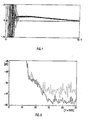
- - Fig. 1 represents a transmission channel pulse response;
- - Fig. 2 is a block diagram of the circuit provided by the invention;
- - Fig. 3 represents the pulse response of a transmission channel with and without the circuit provided by the invention.
- As known, echo-channel pulse response after a first extremely irregular and variable phase, which is a function of the hybrid unbalance, of the line type and of connection topology, has in its final part a quasi-linearly decreasing tail. Fig. 1, relating to some kinds of cables, of subscriber's lines and of connection topological configurations, shows the amplitude in function of time, subdivided into signalling periods.
- This particular tail of pulse response does not depend on the line, in fact the Figure shows also the case of a channel consisting of a resistive termination, but solely of the characteristics of hybrid transformer.
- As it can be noted from this Figure, the amplitude of the tails is still at such a level that requires their cancellation to reach convenient values of residual-echo-to-signal ratio, even in case of maximum length.
- Even though tails only depend on hybrid transformer, they are still random variables, owing to the characteristics of the hybrid itself. In fact, these characteristics can vary either in function of tolerances in the production process or owing to the use of different materials. It is hence necessary to use an adaptive technique for their estimate and cancellation.
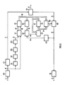
- A bidirectional digital transmission system, comprising the improvements provided by the invention, is shown in Fig. 2.
- Reference 1 denotes the wire whereon the binary signal to be transmitted arrives, 2 the transmission line and 3 the wire whereupon received signals become available.
- The transmitter is represented as subdivided into two blocks NT and LT, where the linear and non-linear parts of line encoding are effected. The encoding is generally based on a three-level code of AMI type. As known, the non-linear part effects a precoding whose aim is that of avoiding error propagation. In fact, since the linear encoding effected in LT is a differential encoding, an erroneous decision in the interpretation of a binary signal would cause the emission of subsequent erroneous signals.
- On wire 4, at NT output, a signal linearly related to the signal sent onto the line is then available and hence a signal which can be used for the estimate of the echo signal to be cancelled. The signal outgoing from LT reaches through
wire 5 hybrid transformer FA and transmission line 2. - The signal coming from the remote transmitter and the echo-signal of local transmitter NT-LT pass through hybrid FA to wire 6, connected to an input of adder SO.
- At the other input, connected to
wire 7, the estimated echo signal is present, which is locally generated with a sign opposite to the echo signal received on wire 6. As a consequence, over wire 8 the echo-deprived useful signal is obtained as an addition effect and is sent to receiver RI to be decoded. - Let us now examine how echo signal ek for tail cancellation is estimated at instant k.
- It is calculatd as a product between the estimated sample of the pulse response of the echo channel, and the summation of symbols b transmitted during the N preceding signalling periods, whose echo queues are to be cancelled.
- The relation is the following:

- The value of I=k is to be estimated in an adaptive way so that the system might match to hybrid having different characteristics. By using the sign iterative-stochastic algorithm, we obtain

- It can be noticed that the argument of the first function sgn in the relation (2) is equal to the second factor of the relation (1). According to the invention, this summation is not calculated by executing N additions every signalling period, but by simply incrementing or decrementing the preceding result in function of the logic level of the binary signal transmitted at the present instant, bk, and of that of the binary signal transmitted N signalling periods before, bk-N.
- To obtain that, precoded signal bk, present on wire 4, is sent both to a shift register consisting of N cells R1, R2, R3...RN, where N is the duration, expressed in signalling periods, of the pulse response of the echo to be cancelled, and to a logic circuit LC. At the other input of LC, connected to wire 9, signal bk- N is present, extracted from the last cell RN of the shift register. The signals at the outputs connected to
wires 
- They are used to control an up/down counter CS, which can be saturated to a maximum counting value N.
- More particularly, the signal on
wire 10 enables the counter CS when at low logic level, and the signal onwire 11 controls up/down counting, according to high or low logic level. - Since CS is a saturable counter, by exploiting the characteristics of line signals with long sequencies of binary 1s, corresponding to the absence of a signal during the initial activation phase or in the transmission frame, both counter CS and shift register R1,...RN need not be initialised, but they have self-positioning characteristics.
- At CS output on
connection 12, the summation of the signals transmitted in the last N signalling periods is then available, its sign is detected by a sign extracting circuit ES and is sent viawire 13 to a multiplying circuit EO, advantageously implemented with a logic EX-OR circuit. - This multiplying circuit receives also the sign of the difference between the estimated echo signal and the actual echo signal, supplied by the sign extracting circuit ET on
wire 15. - The result of the multiplication, present on
wire 14, is sent to a 6-bit adder SP. According to which adder cell the multiplication result is sent to, different values of coefficient D of relation (2) are obtained. As to the present invention aims, the multiplication result is sent to the cell corresponding to the least significant bit. At the other input of adder SP, connected toconnection 16, the result of the preceding sum ĥk-1 arrives delayed by a signalling period by delay circuit TD. At the output of SP, on connection 17, the estimated sample of the pulse response of the echo channel, ĥk by the relation (2), is obtained. - To estimate the echo-signal e, it now is necessary to implement relation (1). Since the tail slope of the echo pulse-response is very low, the most three significant bits of the six bits associated to h, are sufficient. All the three bits are used to represent the amplitude, since it tends to 0 always starting from a positive value.
- The value of h, present on connection 17, is multiplied in a multiplying circuit MB by the summation of the transmitted binary signals, present on
connection 12, and the result, converted into analog form, is sent viawire 7 to adder SO for the cancellation. - The method has been simulated by taking into account the echo pulse responses measured with N=30. To comparison purposes, the suppression value of an echo canceller with 14 taps, i.e. 7 memory taps and 7 transversal ones, is reported deprived of the invention circuit.
- The two results are compared in Fig. 3, where there is also represented the adaptive correction step to render the convergence of the memory part of the canceller faster. The dashed curve relates to the canceller alone, while the solid one comprises also the tail cancelling circuit. In this figure it is also considered the effect of 12-bit D/A converter used in the cancellation.
- It is worth noticing that the gain is of about 6 dB, and 55-dB cancellation values can be attained which are indispensable to ensure a correct operation of the system with lines having an attenuation of 40 dB at 100 kHz.
Claims (5)

Applications Claiming Priority (2)
| Application Number | Priority Date | Filing Date | Title |
|---|---|---|---|
| IT6724986 | 1986-03-27 | ||
| IT8667249A IT1216448B (en) | 1986-03-27 | 1986-03-27 | REFINEMENTS TO ECHO CANCELLERS IN BIDIRECTIONAL NUMERIC TRANSMISSION SYSTEMS |
Publications (2)
| Publication Number | Publication Date |
|---|---|
| EP0246425A1 EP0246425A1 (en) | 1987-11-25 |
| EP0246425B1 true EP0246425B1 (en) | 1990-10-24 |
Family
ID=11300835
Family Applications (1)
| Application Number | Title | Priority Date | Filing Date |
|---|---|---|---|
| EP87104434A Expired EP0246425B1 (en) | 1986-03-27 | 1987-03-25 | Apparatus for cancelling echoes in a duplex digital transmission system |
Country Status (6)
| Country | Link |
|---|---|
| US (1) | US4755984A (en) |
| EP (1) | EP0246425B1 (en) |
| JP (1) | JPH0616580B2 (en) |
| CA (1) | CA1265594A (en) |
| DE (2) | DE246425T1 (en) |
| IT (1) | IT1216448B (en) |
Families Citing this family (7)
| Publication number | Priority date | Publication date | Assignee | Title |
|---|---|---|---|---|
| US5014263A (en) * | 1987-10-02 | 1991-05-07 | Advanced Micro Devices, Inc. | Adaptive echo-canceller with double-talker detection |
| US4982428A (en) * | 1988-12-29 | 1991-01-01 | At&T Bell Laboratories | Arrangement for canceling interference in transmission systems |
| US4995104A (en) * | 1989-05-08 | 1991-02-19 | At&T Bell Laboratories | Interference cancelling circuit and method |
| DE4317043B4 (en) * | 1993-05-21 | 2004-03-25 | Deutsche Telekom Ag | Method and device for echo cancellation in transmission systems |
| US6754187B1 (en) | 2000-04-06 | 2004-06-22 | Inter-Tel, Inc. | Performance enhancement system for digital PBX |
| GB2396279A (en) * | 2002-12-09 | 2004-06-16 | Acuid Corp | Simultaneous bidirectional differential signalling interface with echo cancellation |
| US7702004B2 (en) * | 2002-12-09 | 2010-04-20 | Alexander Roger Deas | Simultaneous bidirectional differential signalling interface |
Family Cites Families (3)
| Publication number | Priority date | Publication date | Assignee | Title |
|---|---|---|---|---|
| US4024358A (en) * | 1975-10-31 | 1977-05-17 | Communications Satellite Corporation (Comsat) | Adaptive echo canceller using differential pulse code modulation encoding |
| GB2123259A (en) * | 1982-06-25 | 1984-01-25 | Philips Electronic Associated | Digital duplex communication system |
| IT1208769B (en) * | 1983-10-12 | 1989-07-10 | Cselt Centro Studi Lab Telecom | THERISTICS VARIATIONS OVER TIME PROCEDURE AND DEVICE FOR THE NUMERICAL CANCELLATION OF THE ECO GENERATED IN CONNECTIONS WITH CARAT |
-
1986
- 1986-03-27 IT IT8667249A patent/IT1216448B/en active
-
1987
- 1987-03-16 US US07/026,483 patent/US4755984A/en not_active Expired - Lifetime
- 1987-03-23 JP JP62065917A patent/JPH0616580B2/en not_active Expired - Lifetime
- 1987-03-25 EP EP87104434A patent/EP0246425B1/en not_active Expired
- 1987-03-25 DE DE198787104434T patent/DE246425T1/en active Pending
- 1987-03-25 CA CA000532956A patent/CA1265594A/en not_active Expired
- 1987-03-25 DE DE8787104434T patent/DE3765692D1/en not_active Expired - Lifetime
Also Published As
| Publication number | Publication date |
|---|---|
| US4755984A (en) | 1988-07-05 |
| CA1265594A (en) | 1990-02-06 |
| IT1216448B (en) | 1990-02-28 |
| DE246425T1 (en) | 1988-04-07 |
| IT8667249A0 (en) | 1986-03-27 |
| DE3765692D1 (en) | 1990-11-29 |
| JPS62265824A (en) | 1987-11-18 |
| JPH0616580B2 (en) | 1994-03-02 |
| EP0246425A1 (en) | 1987-11-25 |
Similar Documents
| Publication | Publication Date | Title |
|---|---|---|
| US4977591A (en) | Dual mode LMS nonlinear data echo canceller | |
| US5388092A (en) | Echo canceller for two-wire full duplex digital data transmission | |
| EP0137508B1 (en) | Method of and device for the digital cancellation of the echo generated in connections with time-varying characteristics | |
| CA2010652C (en) | Echo canceller having fir and iir filters for cancelling long tail echoes | |
| US4268727A (en) | Adaptive digital echo cancellation circuit | |
| US5920548A (en) | Echo path delay estimation | |
| EP0199879B1 (en) | A process and system for improving echo cancellation within a transmission network | |
| EP0530423B1 (en) | Adaptive echo cancellation method and device for implementing said method | |
| US4587382A (en) | Echo canceller using end delay measurement | |
| WO1995017784A1 (en) | Method for determining the location of echo in an echo cancellar | |
| EP0543568A2 (en) | High resolution filtering using low resolution processors | |
| US5014263A (en) | Adaptive echo-canceller with double-talker detection | |
| US4615025A (en) | Data transmission system | |
| US5815496A (en) | Cascade echo canceler arrangement | |
| US4769808A (en) | Method of cancelling echoes in full-duplex data transmission system | |
| EP0246425B1 (en) | Apparatus for cancelling echoes in a duplex digital transmission system | |
| EP0098000B1 (en) | Digital duplex communication system | |
| US4982428A (en) | Arrangement for canceling interference in transmission systems | |
| US4272648A (en) | Gain control apparatus for digital telephone line circuits | |
| Kanemasa et al. | An adaptive-step sign algorithm for fast convergence of a data echo canceller | |
| EP0310055A1 (en) | Adaptive echo-canceller with double-talker detection | |
| EP0098001A2 (en) | Digital duplex communication system | |
| US5084866A (en) | Transversal filter echo canceller | |
| US5461582A (en) | Filter for 2B1Q signals | |
| JPH0541679A (en) | Method for measuring bulk delay for echo canceller for modem |
Legal Events
| Date | Code | Title | Description |
|---|---|---|---|
| PUAI | Public reference made under article 153(3) epc to a published international application that has entered the european phase |
Free format text: ORIGINAL CODE: 0009012 |
|
| AK | Designated contracting states |
Kind code of ref document: A1 Designated state(s): CH DE FR GB LI NL SE |
|
| EL | Fr: translation of claims filed | ||
| 17P | Request for examination filed |
Effective date: 19880112 |
|
| TCNL | Nl: translation of patent claims filed | ||
| DET | De: translation of patent claims | ||
| 17Q | First examination report despatched |
Effective date: 19900228 |
|
| GRAA | (expected) grant |
Free format text: ORIGINAL CODE: 0009210 |
|
| AK | Designated contracting states |
Kind code of ref document: B1 Designated state(s): CH DE FR GB LI NL SE |
|
| REF | Corresponds to: |
Ref document number: 3765692 Country of ref document: DE Date of ref document: 19901129 |
|
| ET | Fr: translation filed | ||
| PLBE | No opposition filed within time limit |
Free format text: ORIGINAL CODE: 0009261 |
|
| STAA | Information on the status of an ep patent application or granted ep patent |
Free format text: STATUS: NO OPPOSITION FILED WITHIN TIME LIMIT |
|
| 26N | No opposition filed | ||
| EAL | Se: european patent in force in sweden |
Ref document number: 87104434.3 |
|
| REG | Reference to a national code |
Ref country code: FR Ref legal event code: CD Ref country code: FR Ref legal event code: TP |
|
| NLS | Nl: assignments of ep-patents |
Owner name: TELECOM ITALIA S.P.A. |
|
| NLT1 | Nl: modifications of names registered in virtue of documents presented to the patent office pursuant to art. 16 a, paragraph 1 |
Owner name: SIP SOCIETA ITALIANA PER L'ESERCIZIO DELLE TELECOM |
|
| REG | Reference to a national code |
Ref country code: CH Ref legal event code: PFA Free format text: SIP SOCIETA ITALIANA PER L'ESERCIZIO TELEFONICO P.A. TRANSFER- TELECOM ITALIA S.P.A. |
|
| REG | Reference to a national code |
Ref country code: GB Ref legal event code: 732E |
|
| PGFP | Annual fee paid to national office [announced via postgrant information from national office to epo] |
Ref country code: CH Payment date: 20010305 Year of fee payment: 15 |
|
| PGFP | Annual fee paid to national office [announced via postgrant information from national office to epo] |
Ref country code: NL Payment date: 20010330 Year of fee payment: 15 |
|
| REG | Reference to a national code |
Ref country code: GB Ref legal event code: IF02 |
|
| PG25 | Lapsed in a contracting state [announced via postgrant information from national office to epo] |
Ref country code: LI Free format text: LAPSE BECAUSE OF NON-PAYMENT OF DUE FEES Effective date: 20020331 Ref country code: CH Free format text: LAPSE BECAUSE OF NON-PAYMENT OF DUE FEES Effective date: 20020331 |
|
| PG25 | Lapsed in a contracting state [announced via postgrant information from national office to epo] |
Ref country code: NL Free format text: LAPSE BECAUSE OF NON-PAYMENT OF DUE FEES Effective date: 20021001 |
|
| REG | Reference to a national code |
Ref country code: CH Ref legal event code: PL |
|
| NLV4 | Nl: lapsed or anulled due to non-payment of the annual fee |
Effective date: 20021001 |
|
| PGFP | Annual fee paid to national office [announced via postgrant information from national office to epo] |
Ref country code: FR Payment date: 20060317 Year of fee payment: 20 |
|
| PGFP | Annual fee paid to national office [announced via postgrant information from national office to epo] |
Ref country code: SE Payment date: 20060329 Year of fee payment: 20 Ref country code: GB Payment date: 20060329 Year of fee payment: 20 |
|
| PGFP | Annual fee paid to national office [announced via postgrant information from national office to epo] |
Ref country code: DE Payment date: 20060502 Year of fee payment: 20 |
|
| PG25 | Lapsed in a contracting state [announced via postgrant information from national office to epo] |
Ref country code: GB Free format text: LAPSE BECAUSE OF EXPIRATION OF PROTECTION Effective date: 20070324 |
|
| EUG | Se: european patent has lapsed |