EP0246327A1 - Method and apparatus for nmr imaging - Google Patents
Method and apparatus for nmr imaging Download PDFInfo
- Publication number
- EP0246327A1 EP0246327A1 EP86906447A EP86906447A EP0246327A1 EP 0246327 A1 EP0246327 A1 EP 0246327A1 EP 86906447 A EP86906447 A EP 86906447A EP 86906447 A EP86906447 A EP 86906447A EP 0246327 A1 EP0246327 A1 EP 0246327A1
- Authority
- EP
- European Patent Office
- Prior art keywords
- signal
- magnetic field
- data
- projection
- nmr
- Prior art date
- Legal status (The legal status is an assumption and is not a legal conclusion. Google has not performed a legal analysis and makes no representation as to the accuracy of the status listed.)
- Ceased
Links
Images


Classifications
-
- G—PHYSICS
- G01—MEASURING; TESTING
- G01R—MEASURING ELECTRIC VARIABLES; MEASURING MAGNETIC VARIABLES
- G01R33/00—Arrangements or instruments for measuring magnetic variables
- G01R33/20—Arrangements or instruments for measuring magnetic variables involving magnetic resonance
- G01R33/44—Arrangements or instruments for measuring magnetic variables involving magnetic resonance using nuclear magnetic resonance [NMR]
- G01R33/48—NMR imaging systems
- G01R33/4818—MR characterised by data acquisition along a specific k-space trajectory or by the temporal order of k-space coverage, e.g. centric or segmented coverage of k-space
- G01R33/482—MR characterised by data acquisition along a specific k-space trajectory or by the temporal order of k-space coverage, e.g. centric or segmented coverage of k-space using a Cartesian trajectory
-
- G—PHYSICS
- G01—MEASURING; TESTING
- G01R—MEASURING ELECTRIC VARIABLES; MEASURING MAGNETIC VARIABLES
- G01R33/00—Arrangements or instruments for measuring magnetic variables
- G01R33/20—Arrangements or instruments for measuring magnetic variables involving magnetic resonance
- G01R33/44—Arrangements or instruments for measuring magnetic variables involving magnetic resonance using nuclear magnetic resonance [NMR]
- G01R33/48—NMR imaging systems
- G01R33/54—Signal processing systems, e.g. using pulse sequences ; Generation or control of pulse sequences; Operator console
- G01R33/56—Image enhancement or correction, e.g. subtraction or averaging techniques, e.g. improvement of signal-to-noise ratio and resolution
- G01R33/561—Image enhancement or correction, e.g. subtraction or averaging techniques, e.g. improvement of signal-to-noise ratio and resolution by reduction of the scanning time, i.e. fast acquiring systems, e.g. using echo-planar pulse sequences
Definitions
- the present invention relates to improvements in an N MR imaging method and apparatus for obtaining a cross-sectional image of an object of inspection by utilizing nuclear magnetic resonance. More particularly, the present invention pertains to an NMR imaging method and apparatus wherein the scanning time required to collect NM R signals by / method the two-dimensional Fourier transformation is reduced.
- An NMR imaging apparatus has a magnet section including a static magnetic field coil for producing a uniform static magnetic field H 0 and a gradient magnetic field coil for producing a magentic field which extends in the same direction as the static magnetic field H o and which has a linear gradient in each of the x, y and z directions, a transmission and reception section which is arranged to apply radio-frequency pulses (radio-frequency electromagnetic wave) to an object of inspection placed within the magnetic field formed by the magnet section and to detect an NMR signal from the object, a control and image processing section which is arranged to contol the operation of the transmission and reception section and that of the magnet section and to process detected data to thereby display an image, and other sections or members.
- radio-frequency pulses radio-frequency electromagnetic wave
- the NMR imaging apparatus having the above-described arrangement is driven in the pulse sequence based on the two-dimensional Fourier transformation as shown in Fig. 6 in order to perform a predetermined data collecting operation.
- the operation carried out at each time during the data collection is as follows.
- the z-gradient magnetic field g s is applied, and a 90° pulse (an RF signal) is applied (see Fig. 6(b) and 6(a)).
- a 90° pulse an RF signal
- spins within a specific slice plane of the object alone are selectively excited.
- the x-gradient magnetic field g d p is applied (see Fig. 6(d)) to give the spins a phase difference corresponding to the x-coordinate (prephase).
- the y-gradient magnetic field g w(k) is applied (see Fig. 6(c)) during the time T w ( ⁇ T 2 ) to give the spins a phase corresponding to the y-coordinate (warp).
- the z-gradient magnetic field g r p is applied during the time T w (see Fig. 6(b)) in order to remove the z-direction phase shift of the spins caused in the slicing operation (rephase).
- the spin echo signal detected during the time T 4 corresponds to one of the lines obtained by subjecting to the two-dimensional Fourier transformation the distribution of intensities of signals from the spins in the object (determined by the spin density and the relaxation phenomenon).
- the selection of lines is effected by means of the product of the amount of application of the y-gradient, i.e., the magnitude of the y-gradient magnetic field g w(k) , and the application time T w . Accordingly, all the view data which is necessary for reconstruction of an image, i.e., a series of data shown in Fig. 7, is collected by repeating the sequence shown in Fig. 6 while varying the y-gradient magnetic field g w(k) . A series of data in the read-out direction shown in Fig. 7 is observed for each view as a spin echo signal, while one of the data in the warp direction is obtained for each view.
- the scanning time in the Fourier transformation is known to be substantially proportional to the number of samples in the warp direction.
- variations in the number of samples in the read-out direction are absorbed into, for example, the stand-by time between successive views and therefore substantially independent of the scanning time. Accordingly, it is only, necessary, in order to shorten the scanning time, to reduce the number of samples in the warp direction.
- the conventional NMR imaging apparatus suffers, however, from the following problems. Since an appropriate number of samples is selected from several different numbers of samples determined in advance, collection of data is not necessarily effected with an optimal scanning time, that is, a necessary, adequate and minimum scanning time, for each individual object. To the contrary, collection of data is carried out in a direction in which the scanning time increases; therefore, there is a fear of the burden on the object increasing and also a risk of an artifact being generated due to the movement of the object's body. Disclosure of the Invention
- projection data concerning an object of inspection is collected from a plurality of directions, and a direction in which the number of samples in the warp direction is minimized is obtained on the basis of the projection data, and then, the scanning coordinate system is rotated in accordance with the obtained direction to collect data on the basis of the Fourier transformation method.
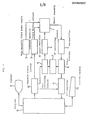
- FIG. 1 is a block diagram of one embodiment of the present invention.
- a magnet assembly 1 has a space portion therein for receiving an object of inspection.
- the following various coils are disposed in such a manner as to surround this space portion: namely, a static magnetic field coil for applying a predetermined static magnetic field H O to the object; a gradient magnetic field coil for generating a gradient magnetic field for each of the x-, y-and z-axes; an RF transmission coil for applying radio-frequency pulses to the object in order to excite nuclear spins within the object; a reception coil for detecting an NMR signal from the object; etc. (not shown).
- a sequence memory circuit 10 has means for generating a sequence signal for collecting projection data from a plurality of directions, sequence control means for effecting collection of data by the spin warp method in a direction in which the number of samples in the warp direction is minimized, said direction being determined in a computer l3 on the basis of the projection data collected from a plurality of directions, and means for controlling the timing at which the detected NMR signal is subjected to analog-to-digiatl (A/D) conversion.
- A/D analog-to-digiatl
- the sequence memory circuit 10 actuates the gradient magnetic field driving circuit 3, a gate modulating circuit 6 and an A/D converter ll.
- the gate modulating circuit 6 modulates a radio-frequency signal from an RF oscillating circuit 7 in response to a timing signal from the sequence memory circuit 10 and applies the modulated radio-frequency signal to the RF power amplifier 4.
- a phase detector 8 uses the output of the RF oscillating circuit 7 as a reference signal to carry out phase detection of an NMR signal which is detected by the reception coil and delivered through the pre-amplifier 5 and applies the NMR signal to the A/D converter 11.
- the A/D converter 11 subjects the NMR signal obtained through the phase detector 8 to analog-to-digital conversion and applies the converted NMR signal to the computer 13.
- the computer 13 exchanges information with a control console 12, rewrites the contents of the sequence memory circuit 10 in order to realize various scanning sequences, performs calculation for reconstructing the distribution of information concerning the resonance energy into an image by the use of data supplied from the A/D converter 11, and outputs data concerning the reconstructed image to a display 9.
- the sequence memory circuit 10 Under a uniform static magnetic field H 0 produced by the main magnetic field power supply 2, the sequence memory circuit 10 actuates the gradient magnetic field driving circuit 3 and the gate modulating circuit 6 in accordance with instructions from the computer l3 so as to generate each of the gradient magnetic fields and radio-frequency pulses in a predetermined sequence.
- the sequence memory circuit 10 further actuates the A/D converter 11 so as to convert an NMR signal detected by the phase detector 8 into a digital signal.
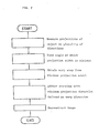
- Fig. 2 illustrates a procedure for scanning carried out by the cooperation of the sequence memory circuit 10 and the computer 13.
- Fig. 2 first, projections of an ob j ce t of inspection in a plurality of directions are width measured, and an angle ⁇ min at which the projection has a minimum value is obtained.
- gradients are applied using the sequence shown in Fig. 3, that is, the sequence based on a known projection reconstruction method and in accordance with the following:
- a warp step g w is obtained from the projection width in the ⁇ min direction. If it is assumed that the projection width in the ⁇ min direction is represented by. f min [ H z], the absolute size of the object as viewed from the ⁇ min direction is obtained from the following formula (1) : wherein: ⁇ ... gyromagnetic ratio
- the warp step ⁇ g w is given by the formula (4) :
- warp gradient g w(k) in the k-th view is given by the formula (5) : wherein: N v ... the number of views
- the effective field of view d in the warp direction is selected so as to be a value obtained by increasing d min in the forumula (3) by about 10% in view of safety.
- the scanning coordinate system is rotated so that the ⁇ min direction is coincident with the warp direction by a known method, and scanning is carried out by the use of the value of g w ( k ) given by the formula (5) and in accordance with the sequence based on the known spin warp method shown in Fig. 6.
- collection of data for reconstructing an image is effected.
- the collected data is then subjected to the two-dimensional / inverse Fourier transformation to reconstruct an image.
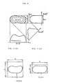
- the scanning time may be considered to be proportional to the number of views N v . Accordingly, if the area of a x b (a > b) shown in Fig. 5(b) is scanned with the direction b defined as the warp direction, the scanning time is reduced by b/a as compared with scanning of the area of a x a shown in Fig. 5(a).
- the scanning coordinate system is rotated in a direction in which the number of samples in the warp direction is minimized on the basis of projection data concerning an object of inspection which is collected from a plurality of directions and an image is reconstructed using data collected under the coordinates obtained thereby. It is therefore possible to effect scanning within a minimum time which can be desired for each individual object. Accordingly, it is possible to reduce the burden on the object and weaken the possibility that an artifact due to the movement of the object's body may be generated.
Landscapes
- Physics & Mathematics (AREA)
- High Energy & Nuclear Physics (AREA)
- Condensed Matter Physics & Semiconductors (AREA)
- General Physics & Mathematics (AREA)
- Health & Medical Sciences (AREA)
- General Health & Medical Sciences (AREA)
- Nuclear Medicine, Radiotherapy & Molecular Imaging (AREA)
- Radiology & Medical Imaging (AREA)
- Engineering & Computer Science (AREA)
- Signal Processing (AREA)
- Magnetic Resonance Imaging Apparatus (AREA)
- Stereoscopic And Panoramic Photography (AREA)
Abstract
A method and apparatus for NMR imaging collects data on each subject in the shortest possible scanning time. Namely, projection data on the subject are collected in a plurality of directions, a direction is found in which the number of samples is the smallest in the warp direction based upon the projection data, and the data are collected by the Fourier method while turning the scan coordinate along the above-found direction.
Description
- The present invention relates to improvements in an NMR imaging method and apparatus for obtaining a cross-sectional image of an object of inspection by utilizing nuclear magnetic resonance. More particularly, the present invention pertains to an NMR imaging method and apparatus wherein the scanning time required to collect NMR signals by / method the two-dimensional Fourier transformation is reduced.
- An NMR imaging apparatus has a magnet section including a static magnetic field coil for producing a uniform static magnetic field H0 and a gradient magnetic field coil for producing a magentic field which extends in the same direction as the static magnetic field Ho and which has a linear gradient in each of the x, y and z directions, a transmission and reception section which is arranged to apply radio-frequency pulses (radio-frequency electromagnetic wave) to an object of inspection placed within the magnetic field formed by the magnet section and to detect an NMR signal from the object, a control and image processing section which is arranged to contol the operation of the transmission and reception section and that of the magnet section and to process detected data to thereby display an image, and other sections or members.
- The NMR imaging apparatus having the above-described arrangement is driven in the pulse sequence based on the two-dimensional Fourier transformation as shown in Fig. 6 in order to perform a predetermined data collecting operation. The operation carried out at each time during the data collection is as follows.
- The time Tl ... The z-gradient magnetic field gs is applied, and a 90° pulse (an RF signal) is applied (see Fig. 6(b) and 6(a)). Thus, spins within a specific slice plane of the object alone are selectively excited.
- The time T2 ... In order to generate a spin echo signal during the subsequent time T4' the x-gradient magnetic field gdp is applied (see Fig. 6(d)) to give the spins a phase difference corresponding to the x-coordinate (prephase). Further, in order to obtain positional data (positional data in the y-direction) in a direction perpendicular to the gradient gpr which is applied when a signal readout operation is carried out, the y-gradient magnetic field gw(k) is applied (see Fig. 6(c)) during the time Tw (<T2) to give the spins a phase corresponding to the y-coordinate (warp). Further, the z-gradient magnetic field grp is applied during the time Tw (see Fig. 6(b)) in order to remove the z-direction phase shift of the spins caused in the slicing operation (rephase).
- The time T3 ... In order to generate a spin echo, a 180° pulse signal is applied (see Fig. 6(a)) to invert the whole spins (inversion).
- The time T4 ... In order to obtain positional data in the x-direction, the x-gradient magnetic field (projection magnetic field ) gpr is applied (see Fig. 6(d)), and a spin echo signal is detected (see Fig. 3(e)).
- The spin echo signal detected during the time T4 corresponds to one of the lines obtained by subjecting to the two-dimensional Fourier transformation the distribution of intensities of signals from the spins in the object (determined by the spin density and the relaxation phenomenon). The selection of lines is effected by means of the product of the amount of application of the y-gradient, i.e., the magnitude of the y-gradient magnetic field gw(k), and the application time Tw. Accordingly, all the view data which is necessary for reconstruction of an image, i.e., a series of data shown in Fig. 7, is collected by repeating the sequence shown in Fig. 6 while varying the y-gradient magnetic field gw(k). A series of data in the read-out direction shown in Fig. 7 is observed for each view as a spin echo signal, while one of the data in the warp direction is obtained for each view.
- /method The scanning time in the Fourier transformation is known to be substantially proportional to the number of samples in the warp direction. On the other hand, variations in the number of samples in the read-out direction are absorbed into, for example, the stand-by time between successive views and therefore substantially independent of the scanning time. Accordingly, it is only, necessary, in order to shorten the scanning time, to reduce the number of samples in the warp direction.
- The conventional NMR imaging apparatus suffers, however, from the following problems. Since an appropriate number of samples is selected from several different numbers of samples determined in advance, collection of data is not necessarily effected with an optimal scanning time, that is, a necessary, adequate and minimum scanning time, for each individual object. To the contrary, collection of data is carried out in a direction in which the scanning time increases; therefore, there is a fear of the burden on the object increasing and also a risk of an artifact being generated due to the movement of the object's body. Disclosure of the Invention
- It is an object of the present invention to provie an NMR imaging method and apparatus which enables scanning to be effected within a minimum time in accordance with a cross-sectional configuration of each object of inspection.
- To this end, in the NMR imaging method and apparatus according to the present invention, projection data concerning an object of inspection is collected from a plurality of directions, and a direction in which the number of samples in the warp direction is minimized is obtained on the basis of the projection data, and then, the scanning coordinate system is rotated in accordance with the obtained direction to collect data on the basis of the Fourier transformation method.
-
- Fig. 1 is a block diagram of one embodiment of the present ivnention;
- Figs. 2 to 5 are views employed to describe the operation of the embodiment of the present invention;
- Fig. 6 shows a pulse sequence in the two-dimensional /method Fourier transformation; and
- Fig. 7 schematically illustrates data obtained in the two-dimensional Fourier transformation.
- The present invention will be described hereinunder in detail with reference to the drawings.
- Fig. 1 is a block diagram of one embodiment of the present invention. A magnet assembly 1 has a space portion therein for receiving an object of inspection. The following various coils are disposed in such a manner as to surround this space portion: namely, a static magnetic field coil for applying a predetermined static magnetic field HO to the object; a gradient magnetic field coil for generating a gradient magnetic field for each of the x-, y-and z-axes; an RF transmission coil for applying radio-frequency pulses to the object in order to excite nuclear spins within the object; a reception coil for detecting an NMR signal from the object; etc. (not shown). The static magnetic field coil, the gradient magnetic field coil, the RF transmission coil and the NMR signal receiving coil are connected to a main magnetic field power supply 2, a gradient magnetic field driving circuit 3, an RF power amplifier 4 and a pre-amplifier 5, respectively. A
sequence memory circuit 10 has means for generating a sequence signal for collecting projection data from a plurality of directions, sequence control means for effecting collection of data by the spin warp method in a direction in which the number of samples in the warp direction is minimized, said direction being determined in a computer l3 on the basis of the projection data collected from a plurality of directions, and means for controlling the timing at which the detected NMR signal is subjected to analog-to-digiatl (A/D) conversion. Thesequence memory circuit 10 actuates the gradient magnetic field driving circuit 3, a gate modulating circuit 6 and an A/D converter ll. The gate modulating circuit 6 modulates a radio-frequency signal from an RF oscillating circuit 7 in response to a timing signal from thesequence memory circuit 10 and applies the modulated radio-frequency signal to theRF power amplifier 4. Aphase detector 8 uses the output of the RF oscillating circuit 7 as a reference signal to carry out phase detection of an NMR signal which is detected by the reception coil and delivered through the pre-amplifier 5 and applies the NMR signal to the A/D converter 11. The A/D converter 11 subjects the NMR signal obtained through thephase detector 8 to analog-to-digital conversion and applies the converted NMR signal to thecomputer 13. Thecomputer 13 exchanges information with acontrol console 12, rewrites the contents of thesequence memory circuit 10 in order to realize various scanning sequences, performs calculation for reconstructing the distribution of information concerning the resonance energy into an image by the use of data supplied from the A/D converter 11, and outputs data concerning the reconstructed image to adisplay 9. - The operation of the above-described arrangement will next be explained.
- Under a uniform static magnetic field H0 produced by the main magnetic field power supply 2, the
sequence memory circuit 10 actuates the gradient magnetic field driving circuit 3 and the gate modulating circuit 6 in accordance with instructions from the computer l3 so as to generate each of the gradient magnetic fields and radio-frequency pulses in a predetermined sequence. Thesequence memory circuit 10 further actuates the A/D converter 11 so as to convert an NMR signal detected by thephase detector 8 into a digital signal. - Fig. 2 illustrates a procedure for scanning carried out by the cooperation of the
sequence memory circuit 10 and thecomputer 13. Referring to Fig. 2, first, projections of an objcet of inspection in a plurality of directions are width measured, and an angle θmin at which the projection has a minimum value is obtained. To obtain a projection in a direction at a desired angle θ, gradients are applied using the sequence shown in Fig. 3, that is, the sequence based on a known projection reconstruction method and in accordance with the following: - gdpl (θ) = gdp cosθ
- gdp2 (θ) = gdp sine
- gprl (θ) = gpr cosθ
- gpr2 (θ) = gpr sine
- Then, a warp step gw is obtained from the projection width in the θmin direction. If it is assumed that the projection width in the θmin direction is represented by. fmin [Hz], the absolute size of the object as viewed from the θmin direction is obtained from the following formula (1) :

- If it it is assumed that the warp step, the effective field of view in the warp direction and the warp time are respectively represented by Δgw, d and Tw, the relationship given by the formula (2) holds and, hence, the formula (3) is obtained:


- Accordingly, the warp step Δgw is given by the formula (4) :

- Further, the warp gradient gw(k) in the k-th view is given by the formula (5) :

- It should be noted that in the actual apparatus the effective field of view d in the warp direction is selected so as to be a value obtained by increasing dmin in the forumula (3) by about 10% in view of safety.
- After the above-described processing, the scanning coordinate system is rotated so that the θmin direction is coincident with the warp direction by a known method, and scanning is carried out by the use of the value of gw(k) given by the formula (5) and in accordance with the sequence based on the known spin warp method shown in Fig. 6. Thus, collection of data for reconstructing an image is effected. The collected data is then subjected to the two-dimensional / inverse Fourier transformation to reconstruct an image. If the maximum amount of warp for obtaining a predetermined resolving power is set at Wmax [rad/cm] , the number of views Nv required therefor is given by the formula (6), and the formula (3) is substituted into the formula (6) to obtain the formula (7) :


- Since in the formula (7) the maximum amount of warp Wmax is determined by the resolving power only, the number of views Nv is proportional to the effective field of view d. Further, the scanning time may be considered to be proportional to the number of views Nv. Accordingly, if the area of a x b (a > b) shown in Fig. 5(b) is scanned with the direction b defined as the warp direction, the scanning time is reduced by b/a as compared with scanning of the area of a x a shown in Fig. 5(a).
- It should be noted that the present invention is not necessarily limited to the above-described embodiment and may be applied to any scanning which uses the Fourier transformation method.
- As has been described above, according to the present invention, the scanning coordinate system is rotated in a direction in which the number of samples in the warp direction is minimized on the basis of projection data concerning an object of inspection which is collected from a plurality of directions and an image is reconstructed using data collected under the coordinates obtained thereby. It is therefore possible to effect scanning within a minimum time which can be desired for each individual object. Accordingly, it is possible to reduce the burden on the object and weaken the possibility that an artifact due to the movement of the object's body may be generated.
- Although the present invention has been described above by way of the best mode for carrying out it, it will be easy for those who have ordinary knowledge of the technical field to which the present invention belongs to make various modifications without departing from the scope of the following claims.
Collected data is then subjected to the Fourier transformation to obtain projection of the object in the c direction as shown in Fig. 4. Projections in a plurality of e directions are obtained, and one which has a minimum projection width is selected therefrom. In the example shown in Fig. 4, θmin = 90°.
Claims (2)
1. In an NMR imaging method wherein a static magnetic field, gradient magnetic fields in x-, y- and z- directions and a radio-frequency electromagnetic wave are applied to an object of inspection to measure an NMR signal from the object, and a cross-sectional image of the object is reconstructed on the basis of the NMR signal, the improvement which comprises:
measuring a projection with respect to a desired cross-section of the object in each of a plurality of directions along this cross-section;
obtaining a direction in which the width of the measured projection is the smallest; and
measuring the NMR signal from the object on the basis of the Fourier transformation in such a manner that a direction which is perpendicur to the obtained direction is defined as the direction of the coordinate axis of the spin warp.
2. In an NMR imaging apparatus having means (1) and (2) for applying a static magnetic field to an object of inspection, means (1) and (3) for applying gradient magnetic fields in x-, y- and z-directions to the object, means (1), (4), (6) and (7) for applying a radio-frequency electromagnetic wave to the object, means (1), (5), (8) and (11) for measuring an NMR signal from the object, and means (13) for reconstructing a cross-sectional image of the object on the basis of the measured NMR signal, the improvement which comprises:
means (10) for measuring a projection with respect to a desired cross-section of the object in each of a plurality of directions along this cross-section;
means (13) for obtaining a direction in which the width of the measured projection is the smallest; and
means (10) for measuring the NMR signal from the object '/method on the basis of the Fourier transformation in such a manner that a direction which is perpendicur to the obtained direction is defined as the direction of the coordinate axis of the spin warp.
Applications Claiming Priority (2)
| Application Number | Priority Date | Filing Date | Title |
|---|---|---|---|
| JP60243598A JPS62103554A (en) | 1985-10-30 | 1985-10-30 | Nmr imaging apparatus |
| JP243598/85 | 1985-10-30 |
Publications (2)
| Publication Number | Publication Date |
|---|---|
| EP0246327A1 true EP0246327A1 (en) | 1987-11-25 |
| EP0246327A4 EP0246327A4 (en) | 1990-01-23 |
Family
ID=17106194
Family Applications (1)
| Application Number | Title | Priority Date | Filing Date |
|---|---|---|---|
| EP19860906447 Ceased EP0246327A4 (en) | 1985-10-30 | 1986-10-29 | Method and apparatus for nmr imaging. |
Country Status (4)
| Country | Link |
|---|---|
| US (1) | US4786871A (en) |
| EP (1) | EP0246327A4 (en) |
| JP (1) | JPS62103554A (en) |
| WO (1) | WO1987002568A2 (en) |
Cited By (3)
| Publication number | Priority date | Publication date | Assignee | Title |
|---|---|---|---|---|
| EP0279584A2 (en) * | 1987-02-19 | 1988-08-24 | Picker International, Inc. | Methods and apparatus for magnetic resonance imaging |
| EP0299070A1 (en) * | 1986-03-18 | 1989-01-18 | Yokogawa Medical Systems, Ltd | Nmr imaging method |
| WO2005091011A1 (en) * | 2004-03-12 | 2005-09-29 | Koninklijke Philips Electronics N.V. | Prescan for optimization of mri scan parameters |
Families Citing this family (4)
| Publication number | Priority date | Publication date | Assignee | Title |
|---|---|---|---|---|
| JP2560299B2 (en) * | 1987-01-13 | 1996-12-04 | 株式会社島津製作所 | NMR tomographic imaging device |
| JP3701616B2 (en) * | 2002-03-06 | 2005-10-05 | ジーイー・メディカル・システムズ・グローバル・テクノロジー・カンパニー・エルエルシー | Magnetic resonance imaging device |
| JP5582687B2 (en) * | 2008-08-26 | 2014-09-03 | 株式会社東芝 | Magnetic resonance imaging system |
| JP2010207568A (en) | 2009-02-10 | 2010-09-24 | Toshiba Corp | Magnetic resonance imaging apparatus |
Citations (3)
| Publication number | Priority date | Publication date | Assignee | Title |
|---|---|---|---|---|
| EP0130479A2 (en) * | 1983-06-30 | 1985-01-09 | General Electric Company | Method of projection reconstruction imaging with reduced sensitivity to motion-related artifacts |
| JPS60152942A (en) * | 1984-01-23 | 1985-08-12 | Toshiba Corp | Nmr-ct scan planning system |
| JPS60157039A (en) * | 1984-01-27 | 1985-08-17 | Hitachi Ltd | Nuclear magnetic resonance imaging apparatus |
Family Cites Families (4)
| Publication number | Priority date | Publication date | Assignee | Title |
|---|---|---|---|---|
| JPS5885145A (en) * | 1981-11-17 | 1983-05-21 | Toshiba Corp | Image recording method in nmr-ct device |
| JPS59148854A (en) * | 1983-02-14 | 1984-08-25 | Hitachi Ltd | Testing apparatus using nuclear magnetic resonance |
| JPS59182351A (en) * | 1983-03-31 | 1984-10-17 | Shimadzu Corp | Nmr tomographic image pickup device |
| US4710716A (en) * | 1985-09-20 | 1987-12-01 | Elscint Ltd. | Slice orientation selection arrangement |
-
1985
- 1985-10-30 JP JP60243598A patent/JPS62103554A/en active Granted
-
1986
- 1986-10-29 WO PCT/JP1986/000545 patent/WO1987002568A2/en not_active Application Discontinuation
- 1986-10-29 US US07/065,358 patent/US4786871A/en not_active Expired - Fee Related
- 1986-10-29 EP EP19860906447 patent/EP0246327A4/en not_active Ceased
Patent Citations (3)
| Publication number | Priority date | Publication date | Assignee | Title |
|---|---|---|---|---|
| EP0130479A2 (en) * | 1983-06-30 | 1985-01-09 | General Electric Company | Method of projection reconstruction imaging with reduced sensitivity to motion-related artifacts |
| JPS60152942A (en) * | 1984-01-23 | 1985-08-12 | Toshiba Corp | Nmr-ct scan planning system |
| JPS60157039A (en) * | 1984-01-27 | 1985-08-17 | Hitachi Ltd | Nuclear magnetic resonance imaging apparatus |
Non-Patent Citations (1)
| Title |
|---|
| See also references of WO8702568A2 * |
Cited By (5)
| Publication number | Priority date | Publication date | Assignee | Title |
|---|---|---|---|---|
| EP0299070A1 (en) * | 1986-03-18 | 1989-01-18 | Yokogawa Medical Systems, Ltd | Nmr imaging method |
| EP0299070A4 (en) * | 1986-03-18 | 1990-11-28 | Yokogawa Medical Systems, Ltd | Nmr imaging method |
| EP0279584A2 (en) * | 1987-02-19 | 1988-08-24 | Picker International, Inc. | Methods and apparatus for magnetic resonance imaging |
| EP0279584A3 (en) * | 1987-02-19 | 1990-12-05 | Picker International, Inc. | Methods and apparatus for magnetic resonance imaging |
| WO2005091011A1 (en) * | 2004-03-12 | 2005-09-29 | Koninklijke Philips Electronics N.V. | Prescan for optimization of mri scan parameters |
Also Published As
| Publication number | Publication date |
|---|---|
| WO1987002568A2 (en) | 1987-05-07 |
| JPH0316851B2 (en) | 1991-03-06 |
| WO1987002568A3 (en) | 1988-04-07 |
| EP0246327A4 (en) | 1990-01-23 |
| US4786871A (en) | 1988-11-22 |
| JPS62103554A (en) | 1987-05-14 |
Similar Documents
| Publication | Publication Date | Title |
|---|---|---|
| US4521733A (en) | NMR Imaging of the transverse relaxation time using multiple spin echo sequences | |
| EP0167350B1 (en) | Nuclear magnetic resonance method and apparatus | |
| US5162730A (en) | Method for operating a magnetic resonant imaging tomography apparatus | |
| EP0112663B1 (en) | Nuclear magnetic resonance methods and apparatus | |
| US5043665A (en) | Magnetic resonance imaging system | |
| JPH0337406B2 (en) | ||
| EP0390086B1 (en) | Magnetic resonance imaging method. | |
| AU754136B2 (en) | Recovery of signal void arising from field inhomogeneities in magnetic resonance echo planar imaging | |
| US4876508A (en) | Method and apparatus for NMR imaging | |
| US4786871A (en) | NMR imaging method and apparatus | |
| US4709211A (en) | Nuclear magnetic resonance system | |
| US4646023A (en) | Nuclear magnetic resonance imaging | |
| US4786872A (en) | NMR imaging method and apparatus | |
| EP0286677B1 (en) | Nmr imaging method | |
| EP0299070B1 (en) | Nmr imaging method | |
| GB2161275A (en) | Nuclear magnetic resonance method and apparatus | |
| EP0600355B1 (en) | Magnetic resonance imaging method and apparatus | |
| US5227726A (en) | Nuclear magnetic resonance methods and apparatus | |
| JPH049414B2 (en) | ||
| EP0153703A2 (en) | NMR imaging apparatus | |
| EP0109517B1 (en) | Nuclear magnetic resonance diagnostic apparatus | |
| JP3478867B2 (en) | Magnetic resonance imaging equipment | |
| SU1126850A1 (en) | Nuclear magnetic resonance-based computing tomograph | |
| JP2961373B2 (en) | Nuclear magnetic resonance imaging system | |
| JPH0531088A (en) | Mr device |
Legal Events
| Date | Code | Title | Description |
|---|---|---|---|
| PUAI | Public reference made under article 153(3) epc to a published international application that has entered the european phase |
Free format text: ORIGINAL CODE: 0009012 |
|
| AK | Designated contracting states |
Kind code of ref document: A1 Designated state(s): DE GB |
|
| 17P | Request for examination filed |
Effective date: 19871028 |
|
| A4 | Supplementary search report drawn up and despatched |
Effective date: 19900123 |
|
| 17Q | First examination report despatched |
Effective date: 19911217 |
|
| STAA | Information on the status of an ep patent application or granted ep patent |
Free format text: STATUS: THE APPLICATION HAS BEEN REFUSED |
|
| 18R | Application refused |
Effective date: 19920606 |
|
| RIN1 | Information on inventor provided before grant (corrected) |
Inventor name: HOSHINO, KAZUYA |