EP0245026B1 - Optical heterodyne mixers providing image-frequency rejection - Google Patents
Optical heterodyne mixers providing image-frequency rejection Download PDFInfo
- Publication number
- EP0245026B1 EP0245026B1 EP87303853A EP87303853A EP0245026B1 EP 0245026 B1 EP0245026 B1 EP 0245026B1 EP 87303853 A EP87303853 A EP 87303853A EP 87303853 A EP87303853 A EP 87303853A EP 0245026 B1 EP0245026 B1 EP 0245026B1
- Authority
- EP
- European Patent Office
- Prior art keywords
- signal
- signals
- optical
- output
- polarization
- Prior art date
- Legal status (The legal status is an assumption and is not a legal conclusion. Google has not performed a legal analysis and makes no representation as to the accuracy of the status listed.)
- Expired - Lifetime
Links
Images


Classifications
-
- H—ELECTRICITY
- H04—ELECTRIC COMMUNICATION TECHNIQUE
- H04B—TRANSMISSION
- H04B10/00—Transmission systems employing electromagnetic waves other than radio-waves, e.g. infrared, visible or ultraviolet light, or employing corpuscular radiation, e.g. quantum communication
- H04B10/60—Receivers
- H04B10/61—Coherent receivers
- H04B10/614—Coherent receivers comprising one or more polarization beam splitters, e.g. polarization multiplexed [PolMux] X-PSK coherent receivers, polarization diversity heterodyne coherent receivers
-
- H—ELECTRICITY
- H04—ELECTRIC COMMUNICATION TECHNIQUE
- H04B—TRANSMISSION
- H04B10/00—Transmission systems employing electromagnetic waves other than radio-waves, e.g. infrared, visible or ultraviolet light, or employing corpuscular radiation, e.g. quantum communication
- H04B10/60—Receivers
- H04B10/61—Coherent receivers
- H04B10/64—Heterodyne, i.e. coherent receivers where, after the opto-electronic conversion, an electrical signal at an intermediate frequency [fIF] is obtained
Landscapes
- Physics & Mathematics (AREA)
- Electromagnetism (AREA)
- Engineering & Computer Science (AREA)
- Computer Networks & Wireless Communication (AREA)
- Signal Processing (AREA)
- Optical Communication System (AREA)
Description
- The present invention relates to optical heterodyne mixers which detect a desired frequency while rejecting interference from any signal at the image frequency.
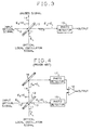
- Optical heterodyne mixers function to combine an incoming optical signal with an optical signal from a local laser to produce an output signal whose frequency is the frequency difference of the two optical signals. The simplest known optical mixer configuration is disclosed in, for example, the book "Laser Communication Systems" by W. K. Pratt, John Wiley & Sons, Inc., 1969, and is shown in FIG. 3. In the mixer of FIG. 3. a received optical signal from a remote source propagating along
path 10, and an optical local oscillator signal propagating along path 11 impinge an optical beam-splitter 12. Each of the two optical outputs from beam-splitter 12 comprise both a component of the received signal and a component of the local oscillator signal frompaths 10 and 11, respectively, which combined components propagate alongpaths splitter 12, which for purposes of illustration will be the output onpath 13, is directed to aphotodetector 15. Since the signals propagating alongpath 14 are wasted, only a fraction of both the received signal and the local oscillator signal is available for detection with this arrangement. Usually, the receiver sensitivity is maximized by using a beam-splitter which transmits most of the received signal. However, with such arrangement, most of the local oscillator signal is then wasted in the unused output of beam-splitter 12, and, therefore, a high power source is required for the local oscillator signal to obtain a receiver performance limited by quantum noise. - A more efficient mixer is provided by a balanced-mixer configuration shown in FIG. 4 and disclosed, for example, in the article by G. L. Abbes et al. in the Globecom '83 Conference Record, Vol. 1, San Diego, Calif., November 28-December 1, 1983, at pages 12.5.1-15.5.6. In FIG. 4, the basic elements 10-15 of FIG. 3 are shown and function as described hereinabove. The signals propagating along
path 14, however, are redirected by adevice 16 to asecond photodetector 17. In such arrangement, the received signal and the local oscillator signal are both combined and then divided equally by beam-splitter 12 into first and-second beams propagating alongpaths photodetectors photodetectors differential amplifier 18 yields a detected signal which is proportional to the available power in the two optical signals. Although the balanced mixer design uses all of the available power, it requires anadditional photodetector 17 and adifferential amplifier 18. - An Image Rejection Mixer (IRM) using a local oscillator (L.O.) signal of frequency f L.O . provides the means to detect simultaneously the two frequencies f L.O. - f IF 1 and f L.O. + f IF 2 and yields the two Intermediate Frequency (IF) signals of frequencies f IF 1 and f IF 2 in first and second outputs, respectively. An optical mixer having this feature is highly desirable for optical Local Area Network (LAN) applications and communication systems using Wavelength Division Multiplex (WDM) techniques. Implementation of an IRM is simple at microwave frequencies using, for example, the arrangement shown in FIG. 5, or image separation mixers as disclosed in the book "Theory Of Resistive Mixers" by A. A. M. Saleh, Cambridge MIT Press, 1971 at pages 168-169. In FIG. 5, the received signal is separated into two equal portions by a 3 dB High Frequency (HF)
coupler 20 for propagation alongseparate paths 21 and 22.Individual mixers paths 21 and 22, respectively, which signals are filtered byrespective IF filters paths 21 and 22 with one coupler output providing the IF signal and the other output providing the IF signal at the image frequency. Unfortunately, transposition of this circuit to optical frequencies is impractical because the optical dimensions of the circuit must be adjusted to a small fraction of an optical wavelength. - U.S. patent 3,215,840 issued to C. F. Buhrer on November 2, 1965, discloses an image rejection optical superheterodyne receiver for receiving single-sideband signals and separating upper and lower sideband optical signals to separate outputs thereof. The Buhrer receiver uses four plane polarisers, a beam splitter, a quarter-wave plate for delaying one of the two orthogonally polarized signals passing therethrough by


- Patent Abstracts of Japan, vol 8, no. 243 (E-277)[1680], 8th November 1984 (and JP-A-59 122 140) discloses apparatus for obtaining heterodyne detection of an optical signal of indeterminate polarization. The signal is first merged with a circularly polarized local oscillator signal. The merged signal is then split into two branches having mutually orthogonal polarizations. The signal in each branch is then converted into an electrical signal and a base-band signal is derived. The base-band signals from the two branches are added to produce the output signal. The object is to attain a stable detecting characteristic independently of the polarization state of the input signal.
- The foregoing problem in the prior art has been solved in accordance with the present invention which relates to optical heterodyne mixers providing image-frequency rejection which comprise a beam-splitter for adding a received optical signal to an optical local oscillator signal. The merged beam then enters a polarizing beam-splitter which separates the two orthogonal polarization components of the merged beam. Each of the two exiting beams from the polarizing beam-splitter is detected separately by an associated photodetector. The resulting two IF currents are added by means of a 3 dB 90 degree IF coupler, where one of the coupler outputs provides the IF signal and the other output yields the IF signal of the image frequency. In the present mixers, the received optical signal(s) is linearly polarized at 45 degrees relative to the polarization axes of the polarizing beam-splitter, while the optical local oscillator signal is circularly polarized, or vice versa.
- In the drawings:
- FIG. 1 is a diagram of an optical heterodyne mixer providing image-frequency rejection in accordance with the present invention;
- FIG.2 is an alternative arrangement of an optical heterodyne mixer providing image-frequency rejection in accordance with the present invention;
- FIG. 3 is a diagram of a single-diode optical mixer known in the prior art;
- FIG. 4 is a diagram of a balanced optical mixer known in the prior art; and
- FIG. 5 is a diagram of an image rejection mixer known in the prior art for use at microwave frequencies.
- An arrangement of an optical heterodyne mixer providing image-frequency rejection in accordance with the present invention is shown in FIG. 1. There, a received optical signal and an optical local oscillator (L.O.) signal are received at separate inputs and directed at an optical merging means such as a
beam splitter 30 which adds the received signal to the L.O. signal. It is to be understood that one of the input signals, either the received signal or the L.O. signal, is linearly polarized, while the other input signal is circularly polarized. Additionally, it should be understood that the received signal can comprise one or more optical signals at different frequencies, where each optical carrier is modulated by a separate information signal. - The merged beam at the output of
beam splitter 30 comprises components of both the received and the L.O. signals and enters a directing means such as and enters a polarizingbeam splitter 31 which functions to separate the horizontal and vertical polarization components of the merged beam. It is to be understood that polarizingbeam splitter 31 should be oriented with its polarization axes at 45 degrees relative to the polarization direction of the input signal which is linearly polarized. Such orientation permits the power of the linearly polarized input signal to be equally divided between the transparent and reflective outputs of polarizingbeam splitter 31, such that equal components of the linearly polarized input signal in the merged beam enterbranches beam splitter 31. It is to be understood thatpolarizing beam splitter 31 also causes equal components of the circularly polarized input signal in the merged beam to enterbranches - Each of the two exiting beams, comprising components of both the linearly and circularly polarized input signals, in
branches photodetectors photodetectors filters coupler 38. One of the coupler outputs, e.g.,output 39, provides, for example, the IF signal while the other output, e.g.,output 40, provides, for example, the IF signal of the image frequency. Each of the output signals can then be processed by separate receivers as desired. It is to be understood that IF filters 36 and 37 may not be necessary when the received signal only comprises one optical signal. but may be necessary where more than one optical signal is included in the received signal. - To describe the mode of operation of the mixer quantitatively, it will be assumed that the L.O. signal is circularly polarized and given by

The quantity P o' represents the power supplied by the L.O. source; x denotes the polarization component which traverses thepolarization beam splitter 31 and y denotes the orthogonal polarization component which is reflected by this device. - It will be further assumed that the received signal is composed of two components; one of radial frequency ω₁ < ω o and power P 1, the other of radial frequency ω₂ > ω o and power P₂. Being linearly polarized in a direction which divides equally their power between the x and y polarization components, these signals can be written as

and

Thebeam splitter 30, used for adding the signals, is assumed to be lossless and nearly transparent to the received signals. Therefore, only a small fraction of the total L.O. power P o' , denoted as P o , is added to the signals given by Equations (2) and (3). The merged beam exiting thebeam splitter 30 is thus given by

The quantities ϑ T and ϑ R represent phase shifts caused bybeam splitter 30 and to satisfy energy conservation are related by

The x-polarization component traversingpolarizing beam splitter 31 arrives atphotodiode 34 with the value
The y-polarization component, being reflected bypolarizing beam splitter 31, reaches thesecond photodiode 35 with the value
The optical phase velocity is given by v, and the quantity L represents the distance between the beam splitter and the point where two polarization components are separated. The phase shift introduced by L is thus the same for the two polarization components when the propagation medium is isotropic. The two other distances D x and D y represent the remaining path lengths for the beams given by Equations (6) and (7) to reach theirrespective photodiodes polarizing beam splitter 31. - After detection, where, P o is assumed to be much larger than P₁ and P₂, and IF filtering, the signals given by Equations (6) and (7) provide the respective IF currents

and
where Ω₁ and Ω₂ are the two IF radial frequencies given by

and

the time t', given by
is nearly the same for the two beams when measured relative to an IF period since it is assumed that
Note that the phases of the currents given by Equations (8) and (9) are insensitive to optical path length fluctuations even if |D x - D y | varies by many optical wavelengths. Among the remaining parameters, e is the charge of an electron, h is Planck's constant and η is the quantum efficiency of thephotodiodes - The last signal processing step consists of adding the currents given by the Equation (8) and (9) by means of a 3 dB 90 degree IF
coupler 38 which is assumed to be lossless. Therefore, to satisfy energy conservation, thecoupler 38 transforms the input currents into the output signals
and
The result yields
and
showing that the IF signals corresponding to the two received optical carriers can be recovered independently. - In the arrangement of FIG. 1
beam splitter 30 passes most of the received signal therethrough topolarizing beam splitter 31 but reflects only a small part of the L.O. signal towardspolarizing beam splitter 31. Such arrangement, therefore, uses the power supplied by the L.O. source at less than peak efficiency. The arrangement of FIG. 2 resolves this minor shortcoming of the arrangement of FIG. 1 by (a) using a 3dB beam splitter 50 instead of a nearlytransparent beam splitter 30, and (b) by adding a polarization rotator 51 in one of the paths provided by 3dB beam splitter 50 to change the direction of polarization in the signal propagating therethrough by
dB beam splitter 50 functions to add the received and L.O. signals and transmit equal portions thereof along a first andsecond output path second output path 54 ofbeam splitter 50, as shown in FIG. 2, and not in thefirst output path 53 ofbeam splitter 50. If necessary, optional redirectingmeans paths polarizing beam splitter 31. Optional redirectingmeans - For purposes of explanation and not for purposes of limitation, it will be assumed hereinafter that the beams in
paths polarizing beam splitter 31. It is to be understood that the direction of arrival ofpaths polarizing beam splitter 31 such that the function described is achieved.Polarizing beam splitter 31 functions as described hereinbefore, which is to be transparent to components in the arriving merged beams inpaths beam splitter 31 and reflects components in the arriving merged beams that include a second polarization direction which is orthogonal to the polarization axis ofpolarizing beam splitter 31. Since polarization rotator 51 rotates the beam inpath 54 so that its polarization direction is now perpendicular to the beam propagating inpath 53 when arriving atpolarizing beam splitter 31, the horizontally polarized components from the beam inpath 53 and the vertically polarized components from the beam inpath 54 are coaxially aligned bypolarizing beam splitter 31 for propagation alongbranch 32 and detection byphotodetector 34. Similarly, the vertically polarized components of the beam propagating inpath 53 and the horizontally polarized components of the beam propagating alongpath 54 are coaxially aligned bypolarizing beam splitter 31 for propagation alongbranch 33 and detection byphotodetector 35. - The output from
photodetectors filters 
and
where L₁ and L₂ are the lengths of the two paths followed by the beams between 3dB beam splitter 30 andpolarizing beam splitter 31 as shown by the dashed lines in FIG. 2. Maximum signal is obtained when L₂ and L₁ are selected to satisfy the conditions
and
This can be achieved if the two IF frequencies are close enough. In this case, the IF signal powers of Equations (18) and (19) become proportional to the entire power P o' supplied by the L.O. source instead of the fraction P o previously available. As a result, an L.O. source of lower power is required to achieve quantum noise-limited performance. - From the foregoing discussion it can be seen that in the present arrangement the use of a linear polarization for one of the two input signals and a circular polarization for the other of the two input signals, and the immediate combination of the two input signals in
beam splitter 30 permits both signals to propagate along the same path topolarizing beam splitter 31. Such arrangement avoids optical path length changes for any one of the two input signals relative to the other input signal when propagating to the input ofpolarizing beam splitter 31. Then, the use of apolarizing beam splitter 31 oriented with its polarization axis at 45 degrees relative to the orientation of the linearly polarized input signal, and the common path being used for the two merged input signals to the input of the polarizing beam splitter, permits proper amplitudes and phases of the polarization components and the outputs ofpolarizing beam splitter 31 to be obtained. Because of such arrangement, any path length differences occurring betweenpolarizing beam splitter 31 and each ofphotodetectors - It is to be understood that the above-described embodiments are simply illustrative of the principles of the invention. Various other modifications and changes may be made by those skilled in the art. For example, in FIG. 2, 3
dB beam splitter 50 can comprise any suitable device such as, for example. an optical coupling device which will merge the received and L.O. signals and then the divide the merged beam into substantially equal output signals. Similarly, the
path 53 rather than inpath 54. With this latter arrangement, the signals normally received byphotodetector 34 in the arrangement shown in FIG. 2 would be received byphotodetector 35 and vice versa, with associated results at the output ofIF coupler 38.
Claims (5)
- An optical heterodyne mixer for providing image-frequency rejection comprising:
a first input terminal for receiving an optical local oscillator input signal having predetermined polarization and a second input terminal for receiving an optical information input signal at a predetermined frequency above or below the local oscillator signal and having a different predetermined polarization;
means for combining said input signals to provide signals directed into a first branch (32) and a second branch (33) such that(A) a first one of said input signals produces signals in said branches that are of equal amplitude and phase and(B) the other of said input signals produces signals in said branches that are of equal amplitude and in phase quadrature;first and second optical detecting means (34,35) disposed in the first and second branches, respectively, for detecting the respective associated optical signals and generating respective first and second intermediate frequency (IF) electrical output signals; and
coupling means (38) for adding the first and second IF output signals and generating (a) a desired IF signal at a first output thereof (39) and (b) an IF signal at the image frequency of the desired IF signal at a second output thereof (40),
CHARACTERIZED IN THAT said combining means comprises means (30) for merging the input signals to propagate along a common path and
means for receiving said merged signal and directing components having a first polarization direction into said first branch and components having a second polarization direction orthogonal to said first polarization direction into said second branch, said polarization directions and the said predetermined polarizations of the input signals being such as to ensure said conditions (A) and (B). - An optical heterodyne mixer according to claim 1 wherein
the first one of the merged polarized first and second input signals at the output of the merging means has a linear polarization which is oriented at 45 degrees to the polarization axis of the directing means, and the second one of the merged first and second input signals at the output of the merging means has a circular polarization. - An optical heterodyne mixer according to claim 1 or 2 wherein
the receiving and directing means comprises a polarizing beam splitter. - An optical heterodyne mixer according to any of the preceding claims wherein the merging means comprises an optical beam splitter.
- An optical heterodyne mixer according to any of the preceding claims wherein
the merging means is arranged to generate a second output signal for propagation along a second output path (54), each of the first and second output signals including substantially equal components of the merged received and local oscillator signals, and the first (53) and second (54) output paths are terminated at separate inputs to the receiving and directing means; and
rotating means (51) are disposed in either one of the first and second output paths of the merging means for rotating the polarization direction of the signal passing therethrough by
Applications Claiming Priority (2)
| Application Number | Priority Date | Filing Date | Title |
|---|---|---|---|
| US860825 | 1986-05-08 | ||
| US06/860,825 US4723317A (en) | 1986-05-08 | 1986-05-08 | Optical heterodyne mixers providing image-frequency rejection |
Publications (3)
| Publication Number | Publication Date |
|---|---|
| EP0245026A2 EP0245026A2 (en) | 1987-11-11 |
| EP0245026A3 EP0245026A3 (en) | 1989-06-07 |
| EP0245026B1 true EP0245026B1 (en) | 1993-07-07 |
Family
ID=25334112
Family Applications (1)
| Application Number | Title | Priority Date | Filing Date |
|---|---|---|---|
| EP87303853A Expired - Lifetime EP0245026B1 (en) | 1986-05-08 | 1987-04-30 | Optical heterodyne mixers providing image-frequency rejection |
Country Status (5)
| Country | Link |
|---|---|
| US (1) | US4723317A (en) |
| EP (1) | EP0245026B1 (en) |
| JP (1) | JPS62272234A (en) |
| CA (1) | CA1256501A (en) |
| DE (1) | DE3786418T2 (en) |
Families Citing this family (16)
| Publication number | Priority date | Publication date | Assignee | Title |
|---|---|---|---|---|
| US4697284A (en) * | 1986-05-08 | 1987-09-29 | American Telephone And Telegraph Company, At&T Bell Laboratories | Single-photodiode optical heterodyne mixers |
| US4723316A (en) * | 1986-05-08 | 1988-02-02 | American Telephone & Telegraph Company, At&T Bell Laboratories | Polarization independent coherent optical heterodyne receivers |
| US4794351A (en) * | 1986-09-29 | 1988-12-27 | American Telephone And Telegraph Company, At&T Bell Laboratories | Optical mixer for upconverting or downconverting an optical signal |
| JPH0734080B2 (en) * | 1988-10-20 | 1995-04-12 | 富士通株式会社 | Heterodyne detection receiver for coherent optical communication |
| EP0393373A3 (en) * | 1989-04-21 | 1992-03-11 | Siemens Aktiengesellschaft | Optical heterodyne receiver |
| US5115332A (en) * | 1989-07-20 | 1992-05-19 | Fujitsu Limited | Receiver for coherent optical communication |
| US4989212A (en) * | 1990-04-09 | 1991-01-29 | Trw, Inc. | Laser diode phase modulation technique |
| US5027436A (en) * | 1990-04-27 | 1991-06-25 | At&T Bell Laboratories | Optical hybrid for coherent detection systems |
| GB2245117B (en) * | 1990-06-14 | 1994-04-06 | Stc Plc | Optical mixing for heterodyne detection |
| EP0485812B1 (en) * | 1990-11-15 | 1995-06-21 | Alcatel SEL Aktiengesellschaft | Device for the optical heterodyne reception of signals |
| US5214796A (en) * | 1991-03-29 | 1993-05-25 | Motorola, Inc. | Image separation mixer |
| DK153791A (en) * | 1991-09-02 | 1993-03-03 | Nkt Res Center As | PROCEDURE FOR COMPRESSION OF RIN IN COHESENT OPTICAL SYSTEMS, LIKE COMMUNICATION RECEIVERS |
| US5410743A (en) * | 1993-06-14 | 1995-04-25 | Motorola, Inc. | Active image separation mixer |
| DE59700268D1 (en) * | 1996-09-22 | 1999-08-26 | Contraves Ag | Method and device for controlling the alignment of two light waves with coherent overlay reception |
| US7466929B2 (en) * | 2004-03-11 | 2008-12-16 | Agilent Technologies, Inc. | Method and system for superheterodyne detection of an optical input signal |
| KR101687118B1 (en) * | 2015-10-12 | 2016-12-28 | 한국과학기술원 | Method for measuring and suppressing phase noise of repetition rate of a femtosecond laser by optical fiber delay line |
Family Cites Families (10)
| Publication number | Priority date | Publication date | Assignee | Title |
|---|---|---|---|---|
| US3215840A (en) * | 1962-11-23 | 1965-11-02 | Gen Telephone & Elect | Image rejecting optical superheterodyne receiver |
| US3975628A (en) * | 1975-04-02 | 1976-08-17 | Hughes Aircraft Company | Optical heterodyne receiver with phase or frequency lock |
| US3970838A (en) * | 1975-08-29 | 1976-07-20 | Hughes Aircraft Company | Dual channel phase locked optical homodyne receiver |
| JPS59122140A (en) * | 1982-12-28 | 1984-07-14 | Nec Corp | Optical heterodyne detector |
| JPS6057824A (en) * | 1983-09-10 | 1985-04-03 | Fujitsu Ltd | Heterodyne optical communication system |
| JPH0618348B2 (en) * | 1984-02-06 | 1994-03-09 | 日本電信電話株式会社 | Optical receiver circuit controller |
| JPS60242435A (en) * | 1984-05-17 | 1985-12-02 | Nec Corp | Polarization diversity optical receiver |
| JPS6123121A (en) * | 1984-07-12 | 1986-01-31 | Nec Corp | Optical heterodyne receiving method |
| US4697284A (en) * | 1986-05-08 | 1987-09-29 | American Telephone And Telegraph Company, At&T Bell Laboratories | Single-photodiode optical heterodyne mixers |
| US4723316A (en) * | 1986-05-08 | 1988-02-02 | American Telephone & Telegraph Company, At&T Bell Laboratories | Polarization independent coherent optical heterodyne receivers |
-
1986
- 1986-05-08 US US06/860,825 patent/US4723317A/en not_active Expired - Lifetime
-
1987
- 1987-04-29 CA CA000535969A patent/CA1256501A/en not_active Expired
- 1987-04-30 DE DE87303853T patent/DE3786418T2/en not_active Expired - Fee Related
- 1987-04-30 EP EP87303853A patent/EP0245026B1/en not_active Expired - Lifetime
- 1987-05-08 JP JP62110931A patent/JPS62272234A/en active Pending
Also Published As
| Publication number | Publication date |
|---|---|
| US4723317A (en) | 1988-02-02 |
| EP0245026A2 (en) | 1987-11-11 |
| JPS62272234A (en) | 1987-11-26 |
| EP0245026A3 (en) | 1989-06-07 |
| CA1256501A (en) | 1989-06-27 |
| DE3786418D1 (en) | 1993-08-12 |
| DE3786418T2 (en) | 1993-10-21 |
Similar Documents
| Publication | Publication Date | Title |
|---|---|---|
| EP0245026B1 (en) | Optical heterodyne mixers providing image-frequency rejection | |
| US5060312A (en) | Polarization independent coherent lightwave detection arrangement | |
| CA1250897A (en) | Optical fibre transmission system with polarization modulation and heterodyne coherent detection | |
| EP0247738B1 (en) | Polarization independent coherent optical heterodyne receivers | |
| EP0409260B1 (en) | Receiver for coherent optical communication | |
| EP0352747B1 (en) | Frequency separation stabilization method for optical heterodyne or optical homodyne communication | |
| US5102222A (en) | Light wave polarization determination using a hybrid system | |
| EP0529617A2 (en) | Optical circuit for a polarization diversity receiver | |
| EP0246004B1 (en) | Single-photodiode optical heterodyne mixers | |
| CA1308440C (en) | Optical receiving method utilizing polarization diversity and apparatus for carrying out the same | |
| US4063084A (en) | Dual channel optical homodyne receiver | |
| US3970838A (en) | Dual channel phase locked optical homodyne receiver | |
| CN111628827A (en) | Coherent optical receiving device and optical signal demodulating device | |
| JPS59122140A (en) | Optical heterodyne detector | |
| US6043921A (en) | Fading-free optical phase rate receiver | |
| EP0260745A1 (en) | Device for optical heterodyne detection of an optical signal beam and optical transmission system provided with such a device | |
| GB2214381A (en) | Optical phase-diversity receivers | |
| JPS6123121A (en) | Optical heterodyne receiving method | |
| JPH07281229A (en) | Optical polarization controller | |
| JPH05158096A (en) | Optical receiver for coherent light wave communication | |
| JPS63224427A (en) | Method and device for polarization diversity optical reception | |
| CA1263445A (en) | Differential phase modulation in an optical fibre communication system | |
| JPH05224267A (en) | Optical receiver | |
| JPH05127125A (en) | Optical receiver for coherent light wave communication | |
| JPS62245741A (en) | Polarization diversity optial reception |
Legal Events
| Date | Code | Title | Description |
|---|---|---|---|
| PUAI | Public reference made under article 153(3) epc to a published international application that has entered the european phase |
Free format text: ORIGINAL CODE: 0009012 |
|
| AK | Designated contracting states |
Kind code of ref document: A2 Designated state(s): DE FR GB IT |
|
| PUAL | Search report despatched |
Free format text: ORIGINAL CODE: 0009013 |
|
| AK | Designated contracting states |
Kind code of ref document: A3 Designated state(s): DE FR GB IT |
|
| 17P | Request for examination filed |
Effective date: 19891129 |
|
| 17Q | First examination report despatched |
Effective date: 19911129 |
|
| GRAA | (expected) grant |
Free format text: ORIGINAL CODE: 0009210 |
|
| AK | Designated contracting states |
Kind code of ref document: B1 Designated state(s): DE FR GB IT |
|
| REF | Corresponds to: |
Ref document number: 3786418 Country of ref document: DE Date of ref document: 19930812 |
|
| ET | Fr: translation filed | ||
| ITF | It: translation for a ep patent filed |
Owner name: MODIANO & ASSOCIATI S.R |
|
| PLBE | No opposition filed within time limit |
Free format text: ORIGINAL CODE: 0009261 |
|
| STAA | Information on the status of an ep patent application or granted ep patent |
Free format text: STATUS: NO OPPOSITION FILED WITHIN TIME LIMIT |
|
| RAP4 | Party data changed (patent owner data changed or rights of a patent transferred) |
Owner name: AT&T CORP. |
|
| 26N | No opposition filed | ||
| PGFP | Annual fee paid to national office [announced via postgrant information from national office to epo] |
Ref country code: FR Payment date: 20010322 Year of fee payment: 15 |
|
| PGFP | Annual fee paid to national office [announced via postgrant information from national office to epo] |
Ref country code: GB Payment date: 20010326 Year of fee payment: 15 |
|
| PGFP | Annual fee paid to national office [announced via postgrant information from national office to epo] |
Ref country code: DE Payment date: 20010629 Year of fee payment: 15 |
|
| REG | Reference to a national code |
Ref country code: GB Ref legal event code: IF02 |
|
| PG25 | Lapsed in a contracting state [announced via postgrant information from national office to epo] |
Ref country code: GB Free format text: LAPSE BECAUSE OF NON-PAYMENT OF DUE FEES Effective date: 20020430 |
|
| PG25 | Lapsed in a contracting state [announced via postgrant information from national office to epo] |
Ref country code: DE Free format text: LAPSE BECAUSE OF NON-PAYMENT OF DUE FEES Effective date: 20021101 |
|
| GBPC | Gb: european patent ceased through non-payment of renewal fee |
Effective date: 20020430 |
|
| PG25 | Lapsed in a contracting state [announced via postgrant information from national office to epo] |
Ref country code: FR Free format text: LAPSE BECAUSE OF NON-PAYMENT OF DUE FEES Effective date: 20021231 |
|
| REG | Reference to a national code |
Ref country code: FR Ref legal event code: ST |
|
| PG25 | Lapsed in a contracting state [announced via postgrant information from national office to epo] |
Ref country code: IT Free format text: LAPSE BECAUSE OF NON-PAYMENT OF DUE FEES Effective date: 20050430 |