EP0245025B1 - Response system of a terminal to an incoming call - Google Patents
Response system of a terminal to an incoming call Download PDFInfo
- Publication number
- EP0245025B1 EP0245025B1 EP87303848A EP87303848A EP0245025B1 EP 0245025 B1 EP0245025 B1 EP 0245025B1 EP 87303848 A EP87303848 A EP 87303848A EP 87303848 A EP87303848 A EP 87303848A EP 0245025 B1 EP0245025 B1 EP 0245025B1
- Authority
- EP
- European Patent Office
- Prior art keywords
- terminal
- time
- call
- message
- response
- Prior art date
- Legal status (The legal status is an assumption and is not a legal conclusion. Google has not performed a legal analysis and makes no representation as to the accuracy of the status listed.)
- Expired - Lifetime
Links
Images


Classifications
-
- H—ELECTRICITY
- H04—ELECTRIC COMMUNICATION TECHNIQUE
- H04Q—SELECTING
- H04Q5/00—Selecting arrangements wherein two or more subscriber stations are connected by the same line to the exchange
-
- H—ELECTRICITY
- H04—ELECTRIC COMMUNICATION TECHNIQUE
- H04Q—SELECTING
- H04Q11/00—Selecting arrangements for multiplex systems
- H04Q11/04—Selecting arrangements for multiplex systems for time-division multiplexing
- H04Q11/0428—Integrated services digital network, i.e. systems for transmission of different types of digitised signals, e.g. speech, data, telecentral, television signals
Definitions
- the present invention relates to a communication terminal which is connected to a communication network and, more particularly, to a system for a communication terminal having an interface which conforms to The Comotti Consultatif International Telecommunicationgraphiqe et Téléphonique (CCITT) Recommendations, I. series, to respond to an incoming call.
- CITT Comotti Consultatif International Telecommunicationgraphiqe et Telecommunicationphonique
- the CCITT named a network for offering a digital communication service Integrated Service Digital Network (ISDN) and, in 1984, gave Recommendations, I. series (Redbook) on basic ISDN items.
- I. series Recommendations on basic ISDN items.
- SETUP call accept message
- a terminal on receipt of a call accept message (SETUP) from a network, a terminal compares the values of its own attributes with those of the service attributes of the call which are contained in the SETUP message so as to decide whether or not to respond to the call and, only when it has decided to respond, sends a respond message CONNect (CONN) to the network.
- CONNect CONN
- a message sent from a network to a terminal for connection is called a SETUP message.
- the SETUP includes various kinds of information elements such as protocol discriminator, call reference, message type, bearer capability, channel identification, progress indicator, terminal capabilities, display, keypad, signal, switchhook, calling party number, calling party subaddress, called party number, called party subaddress, transit network selection, low layer compatibility, high layer compatibility, user-user information (CCITT Q.931).
- the bearer capability, low layer compatibility, high layer compatibility and user-user information are used for compatibility checking which the terminal performs for deciding whether it may answer a call arrived.
- These information elements other than the bearer capability are omitted, as the case may be.
- the terminal has therein a classified table of those contents of the above-stated information elements with which it is compatible, and their items, i.e., attributes as well as their values.
- the terminal decides whether it may accept an incoming call by comparing the contents of a call message arrived with those stored therein.
- a customer premises 20 which is incorporated in an ISDN network 10 includes a point-multipoint bus 22 which is connected to the network 10 via a network termination (NT) 21, that a plurality of terminals (TE) 23, 24, ..., and 2n are present on the bus 22, and that the terminals 23, 24, ..., and 2n share a single subscriber number and have no sub-address.
- NT network termination
- TE terminals
- TE terminals
- a problem with such a prior art response system is that should a particular one of the multiple terminals always return a CONN message before the others, all incoming calls would arrive at that particular terminal and, therefore, a calling user would be incapable of communicating with a desired terminal even though it might repeat origination of a call a number of times.
- German Patent No. 3431420 there is proposed an arrangement in which subscriber terminals are provided with delay means which can be adjusted either to have a random delay time distribution, or manually, in order to provide better utilization of the subscriber terminals.
- a feature of an embodiment to be described is the provision of a communication terminal having a response system to an incoming call which allows a caller to communicate with a desired terminal without fail.
- a further feature of an embodiment to be described is the provision of a response system of a communication terminal to an incoming call which varies the period of time by which the return of a CONN message is delayed, every time the terminal receives a message, so that CONN messages from a plurality of terminals are prevented from conflicting, i.e., the CONN messages are received by a network at different time points.
- a response system of a terminal to an incoming call in a particular embodiment includes means for storing a calling party number and attribute values of a call originated by the calling party when that call is not meant for the terminal, and means for delaying a timing for sending a response message in response to a subsequent incoming call which bears the same calling party number and the same attribute values.
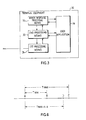
- a terminal equipment (TE) 30 to which the present invention is applied generally comprises a first processing means 31 which is made up of a Layer 1 controller for matching an interface adapted for physical connection and for performing electrical control for bit transmission, and a Layer 2 controller for deciding whether a link is normally usable through, for example, error detection and parity check; a second processing means 32 to which are assigned Layer 3 processing such as state display information processing associated with call origination, response, disconnection and others, and selection control information processing associated with dial enabling, process display, dial number, communication class and others; an annex response processing means 33 details of which will be described later, and a user application means 34 which include a user application and an operation/maintenance application.
- a first processing means 31 which is made up of a Layer 1 controller for matching an interface adapted for physical connection and for performing electrical control for bit transmission, and a Layer 2 controller for deciding whether a link is normally usable through, for example, error detection and parity check
- a second processing means 32 to which are assigned Layer 3 processing such as state
- the annex response processing means 33 includes a signalling means 41, a register 42, and a timing generator 43.
- the signalling means 41 is connected to a signalling section of a digital access signalling system of a communication network via a signalling input/output terminal SG (SGI and SGO), while being connected to the user application 34 of the TE 30 via an application terminal AP (AP1 and AP2). Further, the signalling means 41 is connected to a count-up terminal TCE of the timing generator 43 via a count-up terminal SCE.
- the timing generator 43 is connected to a count start terminal SCS of the signalling means 41 via a count start terminal TCS, and to a control output terminal CO of the register 42 via a control input terminal CI.
- the register 42 is connected to the user application 34 via a state input terminal ST, and to a number-information output terminal SAD of the signalling means 41 via a number-information input terminal RAD.
- the signalling input terminal SGI of the signalling means 41 is connected to a SETUP message comparator (SMC) 411.
- the output of the SMC 411 is delivered via the count start terminal SCS.
- the input terminal SGI is also connected to a calling party number and attribute value extractor (CAE) 412.
- CAE calling party number and attribute value extractor
- the output of the CAE 412 is delivered via the number-information output terminal SAD.
- the signalling input terminal SGI is connected to the application terminal AP1.
- the count-up terminal SCE is connected to an input terminal C of a CONN message transmission delay means (RDC) 413.
- the RDC 413 also has an input terminal A connecting to the application terminal AP2, and an output terminal B connecting to the signalling output terminal SGO.
- the register 42 includes a memory (MEM) 421, and a register command and waiting time subtracter (RS) 422.
- the RAD is connected to an input terminal MI of the MEM 421 while the state input terminal ST is connected to an input terminal RSI of the RS 422.
- the RS 422 has an output terminal RSO connecting to a control input terminal MC of the MEM 421.
- An output terminal MO of the MEM 421 is connected to the control output terminal CO of the register 42.
- a SETUP message from a network is applied to the signalling means 41 via the signalling input terminal SGI.
- the contents of the message are reported to the user application 44, Fig. 3, via the application terminal AP1.
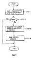
- the signalling means 41 delivers a count start command to the count start terminal TCS of the timing generator 43 via the count start terminal SCS (Fig. 7, STEP 1). This is represented by a time A in Fig. 6, i.e., a SETUP message receipt time.
- the CAE 412 of the signalling means 41 extracts the calling party number and attribute values of the call from the SETUP message and, then, feed them to the number-information input terminal RAD of the register 42 via the number-information output terminal SAD.
- the user application 34 Analyzing the contents of the SETUP message, the user application 34 performs compatibility checking, i.e., it compares "bearer capability” and, if necessary, "low layer compatibility", “high layer compatibility” and "user-user” information elements with those of the own terminal 30 (STEP 2). When decided that the call is compatible with the TE 30 (STEP 3), the user application 34 delivers a respond command to the application terminal AP2.
- the calling party number and the attribute values of the call extracted from the present message by the CAE 412 are applied to the MEM 421 of the register 42 via the terminal MI to be compared with those which were stored at the end of the last call arrival, whereby whether a call of the same contents and originated by the same calling party has ever been erroneously received is decided (STEP 4).
- the MEM 421 delivers a waiting-time set signal n to the input terminal CI of the timing generator 43 via the terminal MO and CO.
- the waiting-time set signal n is incremented by one every time a SETUP message which bears the number of the same calling party number and the same attribute values arrives at the TE 30, while being reset to zero when the TE 30 has actually accepted a call.
- the timing generator 43 When no waiting-time set signal n arrives at the timing generator 43, i.e., when the signal n is zero, the timing generator 43 immediately sends a count-up signal to the terminal SCE of the signalling section 41 via the count-up terminal TCE.
- the RDC 413 of the signalling means 41 When the RDC 413 of the signalling means 41 receives on its terminal A a response signal which is applied to the means 41 from the user application 34 via the terminal AP2 and, at the same time, on its terminal C a count end signal which is delivered to the means 41 from the timing generator 43 via the terminal SCE, the RDC 413 returns a CONN message to the network 10 via the terminals B and SGO (STEP 6).
- a time B is the shortest possible response time
- the interval between the time A and the time B is the shortest response interval T MIN .
- the timing generator 43 executes waiting time processing by one of two predetermined methods as follows.
- the first method is incrementing the waiting time T W every time an incompatible call arrives and, thereby, delaying a response until a maximum period of time T MAX which the network 10 allows expires.
- T W T MIN + n ⁇ ⁇ ⁇ ⁇ T MAX (1) where ⁇ is representative of a unit change of the response interval.
- the timing generator 43 counts time according to the equation (1) on the basis of the waiting-time set signal n which is fed from the MEM 421 and, on the expiry of the waiting time T W , feeds a count-up signal from its count-up terminal TCE to the terminal SCE of the signalling means 41.
- the timing generator 43 delivers a count-up signal via its count-up terminal TCE to the terminal SCE of the signalling means 41 at a time when the period of time elapsed since the count start time A of Fig. 6 reaches the equation (2), e.g., a time D.
- the RDC 413 When the response command from the user application 34 is fed to the input terminal A of the RDC 413 of the signalling means 41 and the count-up signal is fed to the input terminal C, the RDC 413 returns a CONN message from its output terminal B to the network 10 via the signalling output terminal SGO (STEP 6).
- the TE 30 when the TE 30 is to accept a call for the first time, it will return a CONN message on the expiry of the minimum period of time T MIN .
- a call received is not meant for the terminal TE, even though the calling party may call again indicating the same attribute values, a CONN message for that call is delayed and, hence, any other terminal which is returning a CONN message is allowed to accept the call.
- processing subsequent to the start of a communication is executed as follows. After the start of a communication with the other party (STEP 11), whether the communication is normal is determined (STEP 12). If the communication is normal, it is continued without interruption. If the communication is abnormal, the number, attribute values and others of the calling party which were extracted by the CAE 412 and stored into the MEM 421 at the beginning of the communication, as previously stated, are registered in the MEM 421 according to a command given by the user application 34 via the terminal ST (STEP 13). Further, the user application 34 delivers a DISConnect message send command to the second processing means 32, Fig. 3, so as to clear the call. This second processing means 32 and the first processing means 31 execute the processing of the Layers 1 to 3, whereby a DISConnect message is sent to clear the call.
Landscapes
- Engineering & Computer Science (AREA)
- Computer Networks & Wireless Communication (AREA)
- Communication Control (AREA)
Description
- The present invention relates to a communication terminal which is connected to a communication network and, more particularly, to a system for a communication terminal having an interface which conforms to The Comité Consultatif International Télégraphiqe et Téléphonique (CCITT) Recommendations, I. series, to respond to an incoming call.
- The CCITT named a network for offering a digital communication service Integrated Service Digital Network (ISDN) and, in 1984, gave Recommendations, I. series (Redbook) on basic ISDN items. In accordance with the Recommendation I. 451 (CCITT Redbook Vol. III, Fascicle III.5), on receipt of a call accept message (SETUP) from a network, a terminal compares the values of its own attributes with those of the service attributes of the call which are contained in the SETUP message so as to decide whether or not to respond to the call and, only when it has decided to respond, sends a respond message CONNect (CONN) to the network.
- A more specific procedure is as follows.
- A message sent from a network to a terminal for connection is called a SETUP message. The SETUP includes various kinds of information elements such as protocol discriminator, call reference, message type, bearer capability, channel identification, progress indicator, terminal capabilities, display, keypad, signal, switchhook, calling party number, calling party subaddress, called party number, called party subaddress, transit network selection, low layer compatibility, high layer compatibility, user-user information (CCITT Q.931). Among such information elements, the bearer capability, low layer compatibility, high layer compatibility and user-user information are used for compatibility checking which the terminal performs for deciding whether it may answer a call arrived. These information elements other than the bearer capability are omitted, as the case may be. The terminal has therein a classified table of those contents of the above-stated information elements with which it is compatible, and their items, i.e., attributes as well as their values. The terminal decides whether it may accept an incoming call by comparing the contents of a call message arrived with those stored therein.
- Referring to Fig. 1, assume that a
customer premises 20 which is incorporated in an ISDNnetwork 10 includes a point-multipoint bus 22 which is connected to thenetwork 10 via a network termination (NT) 21, that a plurality of terminals (TE) 23, 24, ..., and 2n are present on thebus 22, and that theterminals - As shown in Fig. 2, in the case of a prior art response system as prescribed by the Recommendation I.451, when a SETUP message is broadcast from the
network 10 to theterminals terminal terminals network 10. Then, thenetwork 10 sends a CONNect ACKnowledge (CONN ACK) message to thatterminal 23 which returned the CONN message first, thereby allowing theterminal 23 to answer the call and not theterminal 25. - A problem with such a prior art response system is that should a particular one of the multiple terminals always return a CONN message before the others, all incoming calls would arrive at that particular terminal and, therefore, a calling user would be incapable of communicating with a desired terminal even though it might repeat origination of a call a number of times.
- In German Patent No. 3431420 there is proposed an arrangement in which subscriber terminals are provided with delay means which can be adjusted either to have a random delay time distribution, or manually, in order to provide better utilization of the subscriber terminals.
- A feature of an embodiment to be described is the provision of a communication terminal having a response system to an incoming call which allows a caller to communicate with a desired terminal without fail.
- It will also be understood, from an embodiment to be described, that it is possible to provide a communication terminal with a system that responds to an incoming call in such a way that a calling party number and the attribute values of a call at the instant when a communication was unsuccessful can be caused to be stored in a terminal and, when a message arrives thereafter which is identical in content to that of the stored one, to delay the return of a CONN message from the terminal and thereby to allow another terminal to accept the call.
- A further feature of an embodiment to be described is the provision of a response system of a communication terminal to an incoming call which varies the period of time by which the return of a CONN message is delayed, every time the terminal receives a message, so that CONN messages from a plurality of terminals are prevented from conflicting, i.e., the CONN messages are received by a network at different time points.
- A response system of a terminal to an incoming call in a particular embodiment includes means for storing a calling party number and attribute values of a call originated by the calling party when that call is not meant for the terminal, and means for delaying a timing for sending a response message in response to a subsequent incoming call which bears the same calling party number and the same attribute values.
- Embodiments of the invention will now be described, by way of example, with reference to the accompanying drawings, in which:-
- Fig. 1 is a schematic diagram showing a system construction to which the present invention is applicable;
- Fig. 2 is a sequence diagram representative of message interchange between a communication network and terminals;
- Fig. 3 is a block diagram showing one embodiment of the present invention;
- Fig. 4 is a detailed diagram of one embodiment of the invention;
- Fig. 5 is a flowchart demonstrating a sequence of steps which occur on arrival of a call in accordance with one embodiment of the present invention;
- Fig. 6 is a response timing chart; and
- Fig. 7 is a flowchart demonstrating processing which occurs after the start of a communication.
- In the drawings, the same reference numerals represent the same structural elements.
- Referring to Fig. 3, a terminal equipment (TE) 30 to which the present invention is applied generally comprises a first processing means 31 which is made up of a
Layer 1 controller for matching an interface adapted for physical connection and for performing electrical control for bit transmission, and aLayer 2 controller for deciding whether a link is normally usable through, for example, error detection and parity check; a second processing means 32 to which are assignedLayer 3 processing such as state display information processing associated with call origination, response, disconnection and others, and selection control information processing associated with dial enabling, process display, dial number, communication class and others; an annex response processing means 33 details of which will be described later, and a user application means 34 which include a user application and an operation/maintenance application. - As shown in Fig. 4, the annex response processing means 33 includes a signalling means 41, a
register 42, and atiming generator 43. The signalling means 41 is connected to a signalling section of a digital access signalling system of a communication network via a signalling input/output terminal SG (SGI and SGO), while being connected to theuser application 34 of theTE 30 via an application terminal AP (AP1 and AP2). Further, the signalling means 41 is connected to a count-up terminal TCE of thetiming generator 43 via a count-up terminal SCE. Thetiming generator 43 is connected to a count start terminal SCS of the signalling means 41 via a count start terminal TCS, and to a control output terminal CO of theregister 42 via a control input terminal CI. Theregister 42 is connected to theuser application 34 via a state input terminal ST, and to a number-information output terminal SAD of the signalling means 41 via a number-information input terminal RAD. - In detail, the signalling input terminal SGI of the signalling means 41 is connected to a SETUP message comparator (SMC) 411. The output of the SMC 411 is delivered via the count start terminal SCS. The input terminal SGI is also connected to a calling party number and attribute value extractor (CAE) 412. The output of the CAE 412 is delivered via the number-information output terminal SAD. On the other hand, the signalling input terminal SGI is connected to the application terminal AP1. The count-up terminal SCE is connected to an input terminal C of a CONN message transmission delay means (RDC) 413. The
RDC 413 also has an input terminal A connecting to the application terminal AP2, and an output terminal B connecting to the signalling output terminal SGO. - The
register 42 includes a memory (MEM) 421, and a register command and waiting time subtracter (RS) 422. The RAD is connected to an input terminal MI of theMEM 421 while the state input terminal ST is connected to an input terminal RSI of theRS 422. The RS 422 has an output terminal RSO connecting to a control input terminal MC of theMEM 421. An output terminal MO of theMEM 421 is connected to the control output terminal CO of theregister 42. - The response of the
TE 30 to an incoming call will be described in detail with reference to Figs. 4, 5 and 6. It is to be noted that the operation which will be described also applies to all the other terminal equipment. - A SETUP message from a network is applied to the signalling means 41 via the signalling input terminal SGI. The contents of the message are reported to the user application 44, Fig. 3, via the application terminal AP1. Simultaneously, when the
SMC 411 of the signalling means 41 decides that the SETUP message has been received, the signalling means 41 delivers a count start command to the count start terminal TCS of thetiming generator 43 via the count start terminal SCS (Fig. 7, STEP 1). This is represented by a time A in Fig. 6, i.e., a SETUP message receipt time. TheCAE 412 of the signalling means 41 extracts the calling party number and attribute values of the call from the SETUP message and, then, feed them to the number-information input terminal RAD of theregister 42 via the number-information output terminal SAD. - Analyzing the contents of the SETUP message, the
user application 34 performs compatibility checking, i.e., it compares "bearer capability" and, if necessary, "low layer compatibility", "high layer compatibility" and "user-user" information elements with those of the own terminal 30 (STEP 2). When decided that the call is compatible with the TE 30 (STEP 3), theuser application 34 delivers a respond command to the application terminal AP2. - The calling party number and the attribute values of the call extracted from the present message by the CAE 412 are applied to the
MEM 421 of theregister 42 via the terminal MI to be compared with those which were stored at the end of the last call arrival, whereby whether a call of the same contents and originated by the same calling party has ever been erroneously received is decided (STEP 4). Only under a condition wherein the decision shows that the call arrived is incompatible, that a communication in the event of receipt of the last call was unsuccessful is reported from theuser application 34 to the RS 422 via the state input terminal ST, and the output of theRS 422 is fed to the input terminal MC of theMEM 421, theMEM 421 delivers a waiting-time set signal n to the input terminal CI of thetiming generator 43 via the terminal MO and CO. The waiting-time set signal n is incremented by one every time a SETUP message which bears the number of the same calling party number and the same attribute values arrives at theTE 30, while being reset to zero when the TE 30 has actually accepted a call. - When no waiting-time set signal n arrives at the
timing generator 43, i.e., when the signal n is zero, thetiming generator 43 immediately sends a count-up signal to the terminal SCE of thesignalling section 41 via the count-up terminal TCE. - When the
RDC 413 of the signalling means 41 receives on its terminal A a response signal which is applied to themeans 41 from theuser application 34 via the terminal AP2 and, at the same time, on its terminal C a count end signal which is delivered to themeans 41 from thetiming generator 43 via the terminal SCE, theRDC 413 returns a CONN message to thenetwork 10 via the terminals B and SGO (STEP 6). In Fig. 6, a time B is the shortest possible response time, and the interval between the time A and the time B is the shortest response interval TMIN. - Assume that the waiting-time set signal n is fed from the
MEM 421 of theregister 42 to the CI of thetiming generator 43. Then, thetiming generator 43 executes waiting time processing by one of two predetermined methods as follows. The first method is incrementing the waiting time TW every time an incompatible call arrives and, thereby, delaying a response until a maximum period of time TMAX which thenetwork 10 allows expires. Such a procedure is expressed as

where Δ is representative of a unit change of the response interval. Thetiming generator 43 counts time according to the equation (1) on the basis of the waiting-time set signal n which is fed from theMEM 421 and, on the expiry of the waiting time TW, feeds a count-up signal from its count-up terminal TCE to the terminal SCE of the signalling means 41. - The second method is setting the waiting-time TW as represented by the following equation:

On receipt of the waiting-time set signal n, thetiming generator 43 delivers a count-up signal via its count-up terminal TCE to the terminal SCE of the signalling means 41 at a time when the period of time elapsed since the count start time A of Fig. 6 reaches the equation (2), e.g., a time D. - When the response command from the
user application 34 is fed to the input terminal A of theRDC 413 of the signalling means 41 and the count-up signal is fed to the input terminal C, theRDC 413 returns a CONN message from its output terminal B to thenetwork 10 via the signalling output terminal SGO (STEP 6). - In the above construction, when the
TE 30 is to accept a call for the first time, it will return a CONN message on the expiry of the minimum period of time TMIN. On the other hand, when a call received is not meant for the terminal TE, even though the calling party may call again indicating the same attribute values, a CONN message for that call is delayed and, hence, any other terminal which is returning a CONN message is allowed to accept the call. - Referring to Fig. 7, processing subsequent to the start of a communication is executed as follows. After the start of a communication with the other party (STEP 11), whether the communication is normal is determined (STEP 12). If the communication is normal, it is continued without interruption. If the communication is abnormal, the number, attribute values and others of the calling party which were extracted by the
CAE 412 and stored into theMEM 421 at the beginning of the communication, as previously stated, are registered in theMEM 421 according to a command given by theuser application 34 via the terminal ST (STEP 13). Further, theuser application 34 delivers a DISConnect message send command to the second processing means 32, Fig. 3, so as to clear the call. This second processing means 32 and the first processing means 31 execute the processing of theLayers 1 to 3, whereby a DISConnect message is sent to clear the call.
Claims (2)
- A terminal arranged to provide a response to an incoming call, the terminal including a plurality of communication terminals (23, 24, 25, ..., 2n) which share a single subscriber number, each of the communication terminals (23, 24, 25, ..., 2n) having means (33) for returning a response message when the attribute values of the terminal and the attribute values included in a received message which bears the subscriber number of the respective communication terminal are identical with each other, characterised in that each of the communication terminals (23, 24, 25 ..., 2n) has means (421) for storing at least a calling party number and the attribute values of a call originated by a calling party and received by the respective communication terminal, when the call is not meant for the said respective terminal, and means (43, 413) for delaying the time for sending a response message every time a call which bears the same calling party number and the same attribute values is received up to a period of time determined by the communication terminal.
- A response system of terminal to an incoming call, comprising a plurality of communication terminals (23, 24, 25, ..., 2n) which share a single subscriber number, each of the terminals including means (33) for returning a response message when attribute values of the terminal and attribute values included in a received message which bears the subscriber number of the communication terminal are identical to each other, the response system being characterised in that each of the terminals further includes means (43, 413) for enabling the response means (33) at a time point D when a period of time


Applications Claiming Priority (2)
| Application Number | Priority Date | Filing Date | Title |
|---|---|---|---|
| JP105682/86 | 1986-05-07 | ||
| JP61105682A JPH0685538B2 (en) | 1986-05-07 | 1986-05-07 | Communication terminal incoming response method |
Publications (3)
| Publication Number | Publication Date |
|---|---|
| EP0245025A2 EP0245025A2 (en) | 1987-11-11 |
| EP0245025A3 EP0245025A3 (en) | 1989-05-31 |
| EP0245025B1 true EP0245025B1 (en) | 1993-01-07 |
Family
ID=14414187
Family Applications (1)
| Application Number | Title | Priority Date | Filing Date |
|---|---|---|---|
| EP87303848A Expired - Lifetime EP0245025B1 (en) | 1986-05-07 | 1987-04-29 | Response system of a terminal to an incoming call |
Country Status (5)
| Country | Link |
|---|---|
| US (1) | US4975900A (en) |
| EP (1) | EP0245025B1 (en) |
| JP (1) | JPH0685538B2 (en) |
| CA (1) | CA1288153C (en) |
| DE (1) | DE3783387T2 (en) |
Families Citing this family (11)
| Publication number | Priority date | Publication date | Assignee | Title |
|---|---|---|---|---|
| JP2785835B2 (en) * | 1989-11-20 | 1998-08-13 | 富士通株式会社 | Communication terminal device and communication terminal system using the device |
| JPH03214841A (en) * | 1990-01-19 | 1991-09-20 | Fujitsu Ltd | Modem pool system dependent upon packet communication procedure |
| DE69121609T2 (en) * | 1990-03-16 | 1997-01-23 | Matsushita Graphic Communic | Method and terminal device for processing incoming messages |
| JPH03289732A (en) * | 1990-03-16 | 1991-12-19 | Fujitsu Ltd | Incoming call processing system for plural terminals, and terminal |
| JPH057272A (en) * | 1991-03-11 | 1993-01-14 | Fuji Xerox Co Ltd | Facsimile device |
| JP2538132B2 (en) * | 1991-03-20 | 1996-09-25 | 松下電送株式会社 | Communication control method and ISDN terminal adapter device |
| JP2971625B2 (en) * | 1991-07-04 | 1999-11-08 | 株式会社東芝 | Disconnection reason setting method in electronic exchange |
| US5388095A (en) * | 1993-08-06 | 1995-02-07 | Telefonaktiebolaget L M Ericsson | Representing subscribers in a multiple interface environment switching system |
| JP3419868B2 (en) * | 1993-12-28 | 2003-06-23 | 富士通株式会社 | Signal transmission method |
| EP0710914B1 (en) * | 1994-11-04 | 2000-05-03 | Canon Information Systems, Inc. | Smart programming of flash memory |
| JPH118884A (en) * | 1997-06-18 | 1999-01-12 | Toshiba Corp | Message communication method and device |
Family Cites Families (7)
| Publication number | Priority date | Publication date | Assignee | Title |
|---|---|---|---|---|
| US4379946A (en) * | 1980-06-05 | 1983-04-12 | Nippon Telegraph & Telephone Public Corporation | Signalling system and signal control equipment for multi-address calling |
| JPS59154829A (en) * | 1983-02-24 | 1984-09-03 | Oki Electric Ind Co Ltd | Signal transmission system in avm system |
| JPS611153A (en) * | 1984-05-17 | 1986-01-07 | Fujitsu Ltd | Control method of plural call simultaneous incoming |
| DE3431420C1 (en) * | 1984-08-27 | 1985-10-24 | Telefonbau Und Normalzeit Gmbh, 6000 Frankfurt | Method for achieving an even distribution of load or specific use of telecommunications terminal devices operated on digital connection lines |
| JP2550937B2 (en) * | 1985-03-04 | 1996-11-06 | 国際電信電話株式会社 | ISDN subscriber terminal control system |
| JPS6224746A (en) * | 1985-07-25 | 1987-02-02 | Oki Electric Ind Co Ltd | Terminal control system |
| US4873716A (en) * | 1988-12-27 | 1989-10-10 | American Telephone And Telegraph Company, At&T Bell Laboratories | Path allocation arrangement for multi-terminal groups |
-
1986
- 1986-05-07 JP JP61105682A patent/JPH0685538B2/en not_active Expired - Lifetime
-
1987
- 1987-04-29 EP EP87303848A patent/EP0245025B1/en not_active Expired - Lifetime
- 1987-04-29 DE DE8787303848T patent/DE3783387T2/en not_active Expired - Fee Related
- 1987-05-07 CA CA000536570A patent/CA1288153C/en not_active Expired - Fee Related
-
1989
- 1989-08-01 US US07/388,146 patent/US4975900A/en not_active Expired - Lifetime
Also Published As
| Publication number | Publication date |
|---|---|
| EP0245025A2 (en) | 1987-11-11 |
| JPS62261252A (en) | 1987-11-13 |
| EP0245025A3 (en) | 1989-05-31 |
| DE3783387D1 (en) | 1993-02-18 |
| CA1288153C (en) | 1991-08-27 |
| DE3783387T2 (en) | 1993-05-06 |
| JPH0685538B2 (en) | 1994-10-26 |
| US4975900A (en) | 1990-12-04 |
Similar Documents
| Publication | Publication Date | Title |
|---|---|---|
| EP0323083B1 (en) | Communication terminal apparatus | |
| US5208806A (en) | Isdn terminal equipment operating with circuit switching mode and packet switching mode | |
| EP0245025B1 (en) | Response system of a terminal to an incoming call | |
| EP0430534B1 (en) | Control of non-locally switched telecommunication services | |
| EP0524467A2 (en) | Band management system in communication | |
| US5305313A (en) | Electronic switching system for use in connection to an ISDN and method of setting communication disconnection reasons | |
| JP2616388B2 (en) | Call relief processing method | |
| EP0331531B1 (en) | Telephone apparatus and a method of controlling same | |
| JP3252760B2 (en) | CUG call control method | |
| JP3149262B2 (en) | Communication method for ISDN terminal device | |
| JP2751193B2 (en) | ISDN terminal incoming call priority control method and apparatus | |
| JPH02156763A (en) | Incoming call reply control system in isdn | |
| JPH07307794A (en) | Method and device for testing interface identifier | |
| JPH01209858A (en) | Incoming call control system | |
| JP3169235B2 (en) | ISDN terminal device and call setting control method therefor | |
| JP2739526B2 (en) | Remote terminal maintenance control method | |
| EP1006705A1 (en) | Private telecommunications switching system and method of establishing a connection | |
| JP2794349B2 (en) | Incoming call control method | |
| JP2922541B2 (en) | Message transmission method | |
| JP2735015B2 (en) | Digital communication device | |
| JPH0522473A (en) | Isdn terminal equipment | |
| JPH0371748A (en) | Asynchronous transfer mode communication equipment | |
| KR20030057047A (en) | method for automatically delivering a terminating call of the semi-switching system | |
| JPH0468760A (en) | Facsimile equipment | |
| JPS63284960A (en) | Response system for incoming call for communication terminal |
Legal Events
| Date | Code | Title | Description |
|---|---|---|---|
| PUAI | Public reference made under article 153(3) epc to a published international application that has entered the european phase |
Free format text: ORIGINAL CODE: 0009012 |
|
| 17P | Request for examination filed |
Effective date: 19870512 |
|
| AK | Designated contracting states |
Kind code of ref document: A2 Designated state(s): DE FR GB SE |
|
| PUAL | Search report despatched |
Free format text: ORIGINAL CODE: 0009013 |
|
| AK | Designated contracting states |
Kind code of ref document: A3 Designated state(s): DE FR GB SE |
|
| 17Q | First examination report despatched |
Effective date: 19910612 |
|
| GRAA | (expected) grant |
Free format text: ORIGINAL CODE: 0009210 |
|
| AK | Designated contracting states |
Kind code of ref document: B1 Designated state(s): DE FR GB SE |
|
| REF | Corresponds to: |
Ref document number: 3783387 Country of ref document: DE Date of ref document: 19930218 |
|
| ET | Fr: translation filed | ||
| PLBE | No opposition filed within time limit |
Free format text: ORIGINAL CODE: 0009261 |
|
| STAA | Information on the status of an ep patent application or granted ep patent |
Free format text: STATUS: NO OPPOSITION FILED WITHIN TIME LIMIT |
|
| 26N | No opposition filed | ||
| EAL | Se: european patent in force in sweden |
Ref document number: 87303848.3 |
|
| REG | Reference to a national code |
Ref country code: GB Ref legal event code: IF02 |
|
| PGFP | Annual fee paid to national office [announced via postgrant information from national office to epo] |
Ref country code: FR Payment date: 20020410 Year of fee payment: 16 |
|
| PGFP | Annual fee paid to national office [announced via postgrant information from national office to epo] |
Ref country code: SE Payment date: 20020417 Year of fee payment: 16 |
|
| PGFP | Annual fee paid to national office [announced via postgrant information from national office to epo] |
Ref country code: GB Payment date: 20020424 Year of fee payment: 16 |
|
| PGFP | Annual fee paid to national office [announced via postgrant information from national office to epo] |
Ref country code: DE Payment date: 20020508 Year of fee payment: 16 |
|
| PG25 | Lapsed in a contracting state [announced via postgrant information from national office to epo] |
Ref country code: GB Free format text: LAPSE BECAUSE OF NON-PAYMENT OF DUE FEES Effective date: 20030429 |
|
| PG25 | Lapsed in a contracting state [announced via postgrant information from national office to epo] |
Ref country code: SE Free format text: LAPSE BECAUSE OF NON-PAYMENT OF DUE FEES Effective date: 20030430 |
|
| PG25 | Lapsed in a contracting state [announced via postgrant information from national office to epo] |
Ref country code: DE Free format text: LAPSE BECAUSE OF NON-PAYMENT OF DUE FEES Effective date: 20031101 |
|
| EUG | Se: european patent has lapsed | ||
| GBPC | Gb: european patent ceased through non-payment of renewal fee | ||
| PG25 | Lapsed in a contracting state [announced via postgrant information from national office to epo] |
Ref country code: FR Free format text: LAPSE BECAUSE OF NON-PAYMENT OF DUE FEES Effective date: 20031231 |
|
| REG | Reference to a national code |
Ref country code: FR Ref legal event code: ST |