EP0243239A2 - Installation for transferring heat between a fluid and an organ to be chilled or heated by lowering the fluid pressure with respect to atmospheric pressure - Google Patents
Installation for transferring heat between a fluid and an organ to be chilled or heated by lowering the fluid pressure with respect to atmospheric pressure Download PDFInfo
- Publication number
- EP0243239A2 EP0243239A2 EP87400838A EP87400838A EP0243239A2 EP 0243239 A2 EP0243239 A2 EP 0243239A2 EP 87400838 A EP87400838 A EP 87400838A EP 87400838 A EP87400838 A EP 87400838A EP 0243239 A2 EP0243239 A2 EP 0243239A2
- Authority
- EP
- European Patent Office
- Prior art keywords
- fluid
- heated
- cooled
- installation
- installation according
- Prior art date
- Legal status (The legal status is an assumption and is not a legal conclusion. Google has not performed a legal analysis and makes no representation as to the accuracy of the status listed.)
- Granted
Links
Images
Classifications
-
- H—ELECTRICITY
- H05—ELECTRIC TECHNIQUES NOT OTHERWISE PROVIDED FOR
- H05K—PRINTED CIRCUITS; CASINGS OR CONSTRUCTIONAL DETAILS OF ELECTRIC APPARATUS; MANUFACTURE OF ASSEMBLAGES OF ELECTRICAL COMPONENTS
- H05K7/00—Constructional details common to different types of electric apparatus
- H05K7/20—Modifications to facilitate cooling, ventilating, or heating
- H05K7/20218—Modifications to facilitate cooling, ventilating, or heating using a liquid coolant without phase change in electronic enclosures
- H05K7/20272—Accessories for moving fluid, for expanding fluid, for connecting fluid conduits, for distributing fluid, for removing gas or for preventing leakage, e.g. pumps, tanks or manifolds
Definitions
- Another object of the invention is to achieve this almost automatically and using simple and inexpensive means.
- this depression is obtained thanks to the fact that the fluid in question, in the vicinity of the member to be cooled or heated, has the form of a column enclosed in an enclosure of any shape which plunges at its lower part in a tank subjected to atmospheric pressure.
- a plurality of members to be cooled or heated is in contact with the same column of fluid, which simplifies and makes the corresponding installation less expensive.
- the installation for implementing the method according to the invention comprises a fluid reservoir open to atmospheric pressure, and an enclosure which opens at its lower part into this reservoir and of which a part at less of the inner surface is formed by the member to be cooled or heated.
- this enclosure comprises at least one parallelepiped box or a water / air exchanger, at least one large face of which is formed by the member to be cooled or heated and which is connected by a pipe to the tank specified above.
- the member to be cooled or heated is removably mounted on the corresponding box with possible interposition of an adequate seal. It is understood that this arrangement greatly facilitates the mounting and possible dismantling of the installation.
- the installation comprises a riser to the lower and upper parts of which are connected, respectively, a supply pipe and an outlet pipe, the boxes specified above being connected by pipes corresponding to these supply and outlet pipes.
- the upper part of the rising duct which has just been mentioned comprises a vacuum pump controlled by a level controller, which allows easy filling of the installation, as will be explained below.
- a pump for circulation of the transfer fluid and / or a heat exchanger are mounted at the inlet of the supply pipe specified above.
- the member to be cooled or reheated is constituted by an electronic card, in particular of the type of those which are mounted in computers.
- the heat transfer is of course in the direction of cooling, the transfer fluid used being, for example, a fluorocarbon with low vapor pressure such as that, of formula C6F14, which is marketed under the denomination FC75.
- a fluorocarbon with low vapor pressure such as that, of formula C6F14, which is marketed under the denomination FC75.
- Such products have resistivity very high, that is to say greater than 1015 Ohm / cm, which allows them to be brought into direct contact with the components to be cooled.
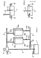
- the installation according to the invention comprises at its lower part a reservoir of heat transfer fluid 1 which communicates with the outside air via a vent 2, so that the free surface of the fluid in the reservoir 1 is at atmospheric pressure.
- a rising pipe 3 plunges into the tank 1 and it is connected at its upper part to a vacuum pump 4 via a level controller 5 whose role will be explained below.
- a substantially horizontal supply pipe 6 is connected to the pipe 3 at its lower part and an outlet pipe 7, which is also substantially horizontal, is connected to this same rising pipe 3 at the level of the level controller 5.
- Between the pipes elements 6a and outlet 7 are mounted elements 8a, 8b, etc., by means of connection pipes 9a, 9b, etc. connecting elements 8a, 8b, etc. corresponding to the supply pipe 6 and connection pipes 10a, 10b, etc. connecting elements 8a, 8b, etc. corresponding to the outlet pipe 7.
- Valves 11a, 11b, etc. are respectively mounted on the connecting pipes 9a, 9b, etc.
- a circulation pump 12 and a heat exchanger 13 can be mounted at the inlet of the pipeline. inlet 6.
- each of the elements 8a, 8b, etc. consists of the member to be cooled or heated which is for example a computer electronic card 14a, 14b, etc. and to which a parallelepiped box 15a, 15b, etc. is applied. whose large corresponding face is open and which is provided with orifices for the connection of the pipes 9a, 9b, etc. and 10a, 10b, etc.
- Appropriate seals can be interposed between the members 14a, 14b, etc. and the corresponding boxes 8a, 8b, etc., which are interconnected by any suitable means such as screws, clamps, or any similar member.
- the operating mode of this installation is as follows: first, fill the reservoir 1 with fluid, then switch on the vacuum pump 4, so that the fluid is sucked into the entire installation, and the controller level 5 stops pump 4 as soon as the level is sufficient. Thanks to the circulation pump 12, the fluid passes through the elements 8a, 8b, etc. where it cools or heats the organs 14a, 14b, etc. Because the pressure of this fluid is lower than atmospheric pressure at this level, any leakage is impossible.
- vent 2 allowing the tank 1 to be brought to atmospheric pressure can be replaced by a more elaborate device which is shown in FIG. 2 and which comprises a regulator 15 which can be supplied with air, neutral gas or any other gas depending on the nature of the fluid used, and a pressure relief valve 16 connected to a discharge pipe or to a recovery system, these two members only working during variations in atmospheric pressure or temperature, or in the event of air entering the circuit.
- a regulator 15 which can be supplied with air, neutral gas or any other gas depending on the nature of the fluid used
- a pressure relief valve 16 connected to a discharge pipe or to a recovery system
- a simple constant level tank is used, the capacity of which may be lower than that of the installation. .
- This tank is then provided a water inlet 18 comprising a float valve and an overflow 19.
- the first is static, and it is the vapor pressure of the liquid used as a function of the temperature.
- the maximum height of the system can theoretically not exceed 8 meters for an atmospheric pressure equal to one bar.
- Another limit is dynamic: if the circulation pump 12 is used, pressure drops must be taken into account to determine the zones where it is desired to maintain a negative relative pressure.
Landscapes
- Engineering & Computer Science (AREA)
- Microelectronics & Electronic Packaging (AREA)
- Physics & Mathematics (AREA)
- Thermal Sciences (AREA)
Abstract
Description
La présente invention concerne un procédé et une installation pour le transfert de chaleur entre un fluide et un organe à refroidir ou à réchauffer, le fluide en question se trouvant normalement en phase liquide.The present invention relates to a method and an installation for the transfer of heat between a fluid and a member to be cooled or heated, the fluid in question normally being in the liquid phase.
Son but est de maintenir ce fluide confiné dans l'installation, sans aucun risque de pertes vers l'extérieur, ce qui est avantageux dans tous les cas, mais présente un intérêt particulier lorsqu'il s'agit de circuits véhiculant des liquides dangereux ou coûteux dont il est impératif d'éviter toute fuite.Its purpose is to keep this fluid confined in the installation, without any risk of losses to the outside, which is advantageous in all cases, but is of particular interest when it comes to circuits conveying dangerous liquids or expensive and it is imperative to avoid any leakage.
Un autre but de l'invention est de réaliser ceci de manière quasi-automatique et grâce à des moyens simples et peu onéreux.Another object of the invention is to achieve this almost automatically and using simple and inexpensive means.
Selon l'invention, ces buts, et d'autres qui apparaîtront par la suite sont atteints grâce au fait que, lors de sa mise en contact avec l'organe à refroidir ou à réchauffer, le fluide de transfert de chaleur présente une dépression par rapport à la pression atmosphérique.According to the invention, these aims, and others which will appear subsequently, are achieved thanks to the fact that, when it is brought into contact with the member to be cooled or heated, the heat transfer fluid exhibits a vacuum by compared to atmospheric pressure.
De préférence, cette dépression est obtenue grâce au fait que le fluide en question, au voisinage de l'organe à refroidir ou à réchauffer, présente la forme d'une colonne enfermée dans une enceinte de forme quelconque qui plonge à sa partie inférieure dans un réservoir soumis à la pression atmosphérique.Preferably, this depression is obtained thanks to the fact that the fluid in question, in the vicinity of the member to be cooled or heated, has the form of a column enclosed in an enclosure of any shape which plunges at its lower part in a tank subjected to atmospheric pressure.
On comprend que, grâce à ces dispositions, la pression interne de l'installation étant toujours négative par rapport à la pression ambiante, un défaut d'étanchéité se traduit seulement par une entrée d'air, puisque le fluide de transfert ne peut pas s'échapper vers l'extérieur.It is understood that, thanks to these provisions, the internal pressure of the installation being always negative with respect to the ambient pressure, a leakage fault only results in an air intake, since the transfer fluid cannot be escape to the outside.
Avantageusement, une pluralité d'organes à refroidir ou à réchauffer est en contact avec la même colonne de fluide, ce qui simplifie et rend moins onéreuse l'installation correspondante.Advantageously, a plurality of members to be cooled or heated is in contact with the same column of fluid, which simplifies and makes the corresponding installation less expensive.
L'installation pour la mise en oeuvre du procédé selon l'invention, tel que défini ci-dessus, comporte un réservoir de fluide ouvert à la pression atmosphérique, et une enceinte qui débouche à sa partie inférieure dans ce réservoir et dont une partie au moins de la surface intérieure est constituée par l'organe à refroidir ou à réchauffer.The installation for implementing the method according to the invention, as defined above, comprises a fluid reservoir open to atmospheric pressure, and an enclosure which opens at its lower part into this reservoir and of which a part at less of the inner surface is formed by the member to be cooled or heated.
Les spécialistes en la matière comprendront aisément que cette disposition permet de maintenir en permanence, et de manière simple, une pression inférieure à la pression ambiante dans l'ensemble de l'enceinte.Specialists in the subject will readily understand that this arrangement makes it possible to permanently maintain, and in a simple manner, a pressure below ambient pressure throughout the enclosure.
De préférence, cette enceinte comporte au moins un caisson parallélépipédique ou un échangeur eau/air dont une grande face au moins est constituée par l'organe à refroidir ou à réchauffer et qui est raccordé par une canalisation au réservoir spécifié ci-avant.Preferably, this enclosure comprises at least one parallelepiped box or a water / air exchanger, at least one large face of which is formed by the member to be cooled or heated and which is connected by a pipe to the tank specified above.
Avantageusement, l'organe à refroidir ou à réchauffer est monté de manière amovible sur le caisson correspondant avec interposition éventuelle d'un joint adéquat. On comprend que cette disposition facilite grandement le montage et le démontage éventuel de l'installation.Advantageously, the member to be cooled or heated is removably mounted on the corresponding box with possible interposition of an adequate seal. It is understood that this arrangement greatly facilitates the mounting and possible dismantling of the installation.
Dans une forme de réalisation particulièrement avantageuse de la présente invention, l'installation comprend un conduit montant aux parties inférieure et supérieure duquel sont raccordées, respectivement, une canalisation d'amenée et une canalisation de sortie, les caissons spécifiés ci-avant étant raccordés par des canalisations correspondantes à ces canalisations d'amenée et de sortie.In a particularly advantageous embodiment of the present invention, the installation comprises a riser to the lower and upper parts of which are connected, respectively, a supply pipe and an outlet pipe, the boxes specified above being connected by pipes corresponding to these supply and outlet pipes.
De préférence, la partie supérieure du conduit montant dont il vient d'être question comporte une pompe à vide commandée par un contrôleur de niveau, ce qui permet un remplissage aisé de l'installation, ainsi que cela sera expliqué plus loin.Preferably, the upper part of the rising duct which has just been mentioned comprises a vacuum pump controlled by a level controller, which allows easy filling of the installation, as will be explained below.
Avantageusement, une pompe de circulation du fluide de transfert et/ou un échangeur de chaleur sont montés à l'entrée de la canalisation d'amenée spécifiée ci-avant.Advantageously, a pump for circulation of the transfer fluid and / or a heat exchanger are mounted at the inlet of the supply pipe specified above.
Dans une forme d'utilisation particulièrement avantageuse de l'invention, l'organe à refroidir ou à réchauffer est constitué par une carte électronique, notamment du genre de celles qui sont montées dans les ordinateurs. Dans ce cas, le transfert de chaleur se fait bien entendu dans le sens du refroidissement, le fluide de transfert employé étant, par example, un fluoro-carbone à faible tension de vapeur tel que celui, de formule C₆F₁₄, qui est commercialisé sous la dénomination FC75. De tels produits présentent une résistivité très élevée, c'est-à-dire supérieure à 10¹⁵ Ohm/cm, ce qui permet de les mettre directement en contact avec les composants à refroidir.In a particularly advantageous form of use of the invention, the member to be cooled or reheated is constituted by an electronic card, in particular of the type of those which are mounted in computers. In this case, the heat transfer is of course in the direction of cooling, the transfer fluid used being, for example, a fluorocarbon with low vapor pressure such as that, of formula C₆F₁₄, which is marketed under the denomination FC75. Such products have resistivity very high, that is to say greater than 10¹⁵ Ohm / cm, which allows them to be brought into direct contact with the components to be cooled.
La description qui va suivre, et qui ne présente aucun caractère limitatif, permettra de bien comprendre comment la présente invention peut être mise en pratique. Elle doit être lue en regard des dessins annexés, parmi lesquels :
- - La figure 1 représente un schéma de principe d'une installation de transfert de chaleur selon l'invention dans l'une de ses formes de réalisation ; et :
- - Les figures 2 et 3 montrent également des schémas de principe et elles représentent des variantes d'une partie de l'installation de la figure 1.
- - Figure 1 shows a block diagram of a heat transfer installation according to the invention in one of its embodiments; and:
- - Figures 2 and 3 also show block diagrams and they represent variants of part of the installation of Figure 1.
Comme on le voit sur la figure 1, l'installation selon l'invention comprend à sa partie inférieure un réservoir de fluide de transfert de chaleur 1 qui communique avec l'air extérieur par l'intermédiaire d'un évent 2, de sorte que la surface libre du fluide dans le réservoir 1 se trouve à la pression atmosphérique.As can be seen in FIG. 1, the installation according to the invention comprises at its lower part a reservoir of heat transfer fluid 1 which communicates with the outside air via a
Un conduit montant 3 plonge dans le réservoir 1 et il est raccordé à sa partie supérieure à une pompe à vide 4 par l'intermédiaire d'un contrôleur de niveau 5 dont le rôle sera précisé plus loin.A rising
Une canalisation d'amenée 6 sensiblement horizontale est branchée sur le conduit 3 à sa partie basse et une canalisation de sortie 7, elle aussi sensiblement horizontale, est raccordée à ce même conduit montant 3 à la hauteur du contrôleur de niveau 5. Entre les canalisations d'amenée 6 et de sortie 7 sont montés des éléments 8a, 8b, etc., par l'intermédiaire de canalisations de raccordement 9a, 9b, etc. reliant les éléments 8a, 8b, etc. correspondants à la canalisation d'amenée 6 et de canalisations de raccordement 10a, 10b, etc. reliant les éléments 8a, 8b, etc. correspondants à la canalisation de sortie 7. Des vannes 11a, 11b, etc. sont respectivement montées sur les canalisations de raccordement 9a, 9b, etc. Enfin, une pompe de circulation 12 et un échangeur de chaleur 13 peuvent être montés à l'entrée de la canalisation d'amenée 6.A substantially horizontal supply pipe 6 is connected to the
Pour leur part, chacun des éléments 8a, 8b, etc. est constitué par l'organe à refroidir ou à chauffer qui est par exemple une carte électronique d'ordinateur 14a, 14b, etc. et sur lequel s'applique un caisson parallélépipédique 15a, 15b, etc. dontla grande face correspondante est ouverte et qui est muni d'orifices pour le raccordement des canalisations 9a, 9b, etc. et 10a, 10b, etc. Des joints appropriés non représentés peuvent être interposés entre les organes 14a, 14b, etc. et les caissons correspondants 8a, 8b, etc., lesquels sont reliés entre eux par tout moyen convenable comme des vis, des pinces, ou tout organe analogue.For their part, each of the
Le mode de fonctionnement de cette installation est le suivant : on commence par remplir de fluide le réservoir 1, puis on enclenche la pompe à vide 4, de sorte que le fluide se trouve aspiré dans l'ensemble de l'installation, et le contrôleur de niveau 5 arrête la pompe 4 dès que le niveau est suffisant. Grâce à la pompe de circulation 12, le fluide traverse les éléments 8a, 8b, etc. où il refroidit ou chauffe les organes 14a, 14b, etc. Du fait que la pression de ce fluide est inférieure à la pression atmosphérique à ce niveau, toute fuite est impossible.The operating mode of this installation is as follows: first, fill the reservoir 1 with fluid, then switch on the vacuum pump 4, so that the fluid is sucked into the entire installation, and the
Dans le cas où l'on veut éviter toute perte par évaporation, l'évent 2 permettant la mise à la pression atmosphérique du réservoir 1 peut être remplacé par un dispositif plus élaboré qui est représenté sur la figure 2 et qui comprend un détendeur 15 pouvant être alimenté en air, en gaz neutre ou en tout autre gaz en fonction de la nature du fluide employé, et une soupape de surpression 16 raccordée à une conduite d'évacuation ou à un système de récupération, ces deux organes ne travaillant que lors de variations de la pression atmosphérique ou de la température, ou encore en cas d'entrée d'air dans le circuit.In the case where it is desired to avoid any loss by evaporation, the
Dans la variante qui est représentée sur la figure 3 et qui correspond plus particulièrement au cas où le fluide de transfert de chaleur est de l'eau, on utilise un simple réservoir à niveau constant dont la capacité peut être inférieure à celle de l'installation. Ce réservoir est alors muni d'une arrivée d'eau 18 comprenant un robinet à flotteur et d'un trop-plein 19.In the variant which is represented in FIG. 3 and which corresponds more particularly to the case where the heat transfer fluid is water, a simple constant level tank is used, the capacity of which may be lower than that of the installation. . This tank is then provided a
On indiquera encore certaines limites d'emploi du système qui vient d'être décrit : la première est statique, et il s'agit de la tension de vapeur du liquide employé en fonction de la température. C'est ainsi que, pour de l'eau à 60°C, la hauteur maximale du système ne peut théoriquement pas dépasser 8 mètres pour une pression atmosphérique égale à un bar. Une autre limite est d'ordre dynamique : si l'on emploie la pompe de circulation 12, il faut tenir compte des pertes de charge pour déterminer les zones où l'on veut maintenir une pression relative négative.We will also indicate certain limits of use of the system which has just been described: the first is static, and it is the vapor pressure of the liquid used as a function of the temperature. Thus, for water at 60 ° C, the maximum height of the system can theoretically not exceed 8 meters for an atmospheric pressure equal to one bar. Another limit is dynamic: if the
Lorsqu'un défaut d'etanchéité prend naissance dans l'installation selon l'invention, et s'il s'agit d'une fuite de faible valeur, elle se traduit par une entrée d'air qui s'accumule dans le contrôleur de niveau 5. Dès que le niveau du liquide atteint la limite inférieure prévue pour ce contrôleur, la pompe 4 s'enclenche à nouveau et elle évacue l'air accumulé. Le contrôle du temps de marche de la pompe 4 permet de déterminer avec précision la valeur des fuites, ces dernières ne devenant gênantes que si la pompe ne peut plus suffire à évacuer la quantité d'air introduite.When a leak occurs in the installation according to the invention, and if it is a low value leak, it results in an air intake which accumulates in the
Au contraire, dans le cas extrême où se produit la rupture franche d'un conduit, la pompe 4 est incapable d'aspirer l'air qui s'introduit dans l'installation, et la pression atmosphérique tend à s'établir dans le circuit. La seule conséquence d'un incident de ce genre est le retour du liquide vers le réservoir 1, retour qui a lieu pratiquement sans perte de liquide.On the contrary, in the extreme case where a frank break in a pipe occurs, the pump 4 is unable to suck in the air which enters the installation, and atmospheric pressure tends to be established in the circuit. . The only consequence of an incident of this kind is the return of the liquid to the reservoir 1, return which takes place practically without loss of liquid.
Il y a lieu de noter enfin que l'un au moins des caissons 8 pourrait être remplacé par un écahngeur de chaleur eau/air non représenté.Finally, it should be noted that at least one of the boxes 8 could be replaced by a water / air heat exchanger not shown.
Claims (10)
Applications Claiming Priority (2)
| Application Number | Priority Date | Filing Date | Title |
|---|---|---|---|
| FR8605846 | 1986-04-23 | ||
| FR8605846A FR2602035B1 (en) | 1986-04-23 | 1986-04-23 | METHOD AND APPARATUS FOR TRANSFERRING HEAT BETWEEN A FLUID AND A COOLING OR HEATING MEMBER BY DEPRESSION OF THE FLUID WITH RESPECT TO ATMOSPHERIC PRESSURE |
Publications (3)
| Publication Number | Publication Date |
|---|---|
| EP0243239A2 true EP0243239A2 (en) | 1987-10-28 |
| EP0243239A3 EP0243239A3 (en) | 1989-06-14 |
| EP0243239B1 EP0243239B1 (en) | 1994-06-22 |
Family
ID=9334526
Family Applications (1)
| Application Number | Title | Priority Date | Filing Date |
|---|---|---|---|
| EP19870400838 Expired - Lifetime EP0243239B1 (en) | 1986-04-23 | 1987-04-14 | Installation for transferring heat between a fluid and an organ to be chilled or heated by lowering the fluid pressure with respect to atmospheric pressure |
Country Status (3)
| Country | Link |
|---|---|
| EP (1) | EP0243239B1 (en) |
| DE (1) | DE3750099T2 (en) |
| FR (1) | FR2602035B1 (en) |
Cited By (17)
| Publication number | Priority date | Publication date | Assignee | Title |
|---|---|---|---|---|
| EP0488926A1 (en) * | 1990-11-30 | 1992-06-03 | Pau Urbina Casanovas | Procedure to increase the temperature in a closed circuit heating system, working on any kind of calorific energy basis |
| GB2316237A (en) * | 1996-08-06 | 1998-02-18 | Advantest Corp | Cooling of electronic devices mounted on a circuit board |
| WO2000065890A1 (en) * | 1999-04-27 | 2000-11-02 | Abb Ab | A device at electrical apparatuses having a cooling arrangement and a method for avoiding losses of cooling medium |
| EP1380799A3 (en) * | 2002-07-11 | 2004-12-15 | Raytheon Company | Method and apparatus for cooling with coolant at a subambient pressure |
| US6937471B1 (en) | 2002-07-11 | 2005-08-30 | Raytheon Company | Method and apparatus for removing heat from a circuit |
| US6957550B2 (en) | 2003-05-19 | 2005-10-25 | Raytheon Company | Method and apparatus for extracting non-condensable gases in a cooling system |
| US7254957B2 (en) | 2005-02-15 | 2007-08-14 | Raytheon Company | Method and apparatus for cooling with coolant at a subambient pressure |
| WO2009055142A1 (en) * | 2007-10-25 | 2009-04-30 | Raytheon Company | System and method for cooling structures having both an active state and an inactive state |
| GB2465140A (en) * | 2008-10-30 | 2010-05-12 | Aqua Cooling Solutions Ltd | Heat exchange apparatus for an electronic or computer system |
| WO2010086098A1 (en) * | 2009-02-02 | 2010-08-05 | Knürr AG | Method and arrangement for cooling electrical and electronic components and module units in electrical enclosures |
| US7908874B2 (en) | 2006-05-02 | 2011-03-22 | Raytheon Company | Method and apparatus for cooling electronics with a coolant at a subambient pressure |
| US7921655B2 (en) | 2007-09-21 | 2011-04-12 | Raytheon Company | Topping cycle for a sub-ambient cooling system |
| US7934386B2 (en) | 2008-02-25 | 2011-05-03 | Raytheon Company | System and method for cooling a heat generating structure |
| US8341965B2 (en) | 2004-06-24 | 2013-01-01 | Raytheon Company | Method and system for cooling |
| US8651172B2 (en) | 2007-03-22 | 2014-02-18 | Raytheon Company | System and method for separating components of a fluid coolant for cooling a structure |
| US9383145B2 (en) | 2005-11-30 | 2016-07-05 | Raytheon Company | System and method of boiling heat transfer using self-induced coolant transport and impingements |
| CN106465562A (en) * | 2015-10-23 | 2017-02-22 | 华为技术有限公司 | Heat pipe cooling system and power equipment |
Families Citing this family (1)
| Publication number | Priority date | Publication date | Assignee | Title |
|---|---|---|---|---|
| US7907409B2 (en) | 2008-03-25 | 2011-03-15 | Raytheon Company | Systems and methods for cooling a computing component in a computing rack |
Citations (4)
| Publication number | Priority date | Publication date | Assignee | Title |
|---|---|---|---|---|
| US3481393A (en) * | 1968-01-15 | 1969-12-02 | Ibm | Modular cooling system |
| US3757530A (en) * | 1972-04-12 | 1973-09-11 | Control Data Corp | Cooling system for data processing apparatus |
| US3992894A (en) * | 1975-12-22 | 1976-11-23 | International Business Machines Corporation | Inter-active dual loop cooling system |
| US4698728A (en) * | 1986-10-14 | 1987-10-06 | Unisys Corporation | Leak tolerant liquid cooling system |
-
1986
- 1986-04-23 FR FR8605846A patent/FR2602035B1/en not_active Expired - Fee Related
-
1987
- 1987-04-14 EP EP19870400838 patent/EP0243239B1/en not_active Expired - Lifetime
- 1987-04-14 DE DE19873750099 patent/DE3750099T2/en not_active Expired - Fee Related
Patent Citations (4)
| Publication number | Priority date | Publication date | Assignee | Title |
|---|---|---|---|---|
| US3481393A (en) * | 1968-01-15 | 1969-12-02 | Ibm | Modular cooling system |
| US3757530A (en) * | 1972-04-12 | 1973-09-11 | Control Data Corp | Cooling system for data processing apparatus |
| US3992894A (en) * | 1975-12-22 | 1976-11-23 | International Business Machines Corporation | Inter-active dual loop cooling system |
| US4698728A (en) * | 1986-10-14 | 1987-10-06 | Unisys Corporation | Leak tolerant liquid cooling system |
Cited By (26)
| Publication number | Priority date | Publication date | Assignee | Title |
|---|---|---|---|---|
| EP0488926A1 (en) * | 1990-11-30 | 1992-06-03 | Pau Urbina Casanovas | Procedure to increase the temperature in a closed circuit heating system, working on any kind of calorific energy basis |
| GB2316237A (en) * | 1996-08-06 | 1998-02-18 | Advantest Corp | Cooling of electronic devices mounted on a circuit board |
| US6052284A (en) * | 1996-08-06 | 2000-04-18 | Advantest Corporation | Printed circuit board with electronic devices mounted thereon |
| GB2316237B (en) * | 1996-08-06 | 2001-09-12 | Advantest Corp | Printed circuit board with electronic devices mounted thereon |
| WO2000065890A1 (en) * | 1999-04-27 | 2000-11-02 | Abb Ab | A device at electrical apparatuses having a cooling arrangement and a method for avoiding losses of cooling medium |
| US7607475B2 (en) | 2002-07-11 | 2009-10-27 | Raytheon Company | Apparatus for cooling with coolant at subambient pressure |
| EP1380799A3 (en) * | 2002-07-11 | 2004-12-15 | Raytheon Company | Method and apparatus for cooling with coolant at a subambient pressure |
| US6937471B1 (en) | 2002-07-11 | 2005-08-30 | Raytheon Company | Method and apparatus for removing heat from a circuit |
| US7000691B1 (en) | 2002-07-11 | 2006-02-21 | Raytheon Company | Method and apparatus for cooling with coolant at a subambient pressure |
| US6957550B2 (en) | 2003-05-19 | 2005-10-25 | Raytheon Company | Method and apparatus for extracting non-condensable gases in a cooling system |
| US8341965B2 (en) | 2004-06-24 | 2013-01-01 | Raytheon Company | Method and system for cooling |
| US7254957B2 (en) | 2005-02-15 | 2007-08-14 | Raytheon Company | Method and apparatus for cooling with coolant at a subambient pressure |
| US9383145B2 (en) | 2005-11-30 | 2016-07-05 | Raytheon Company | System and method of boiling heat transfer using self-induced coolant transport and impingements |
| US8490418B2 (en) | 2006-05-02 | 2013-07-23 | Raytheon Company | Method and apparatus for cooling electronics with a coolant at a subambient pressure |
| US7908874B2 (en) | 2006-05-02 | 2011-03-22 | Raytheon Company | Method and apparatus for cooling electronics with a coolant at a subambient pressure |
| US8651172B2 (en) | 2007-03-22 | 2014-02-18 | Raytheon Company | System and method for separating components of a fluid coolant for cooling a structure |
| US7921655B2 (en) | 2007-09-21 | 2011-04-12 | Raytheon Company | Topping cycle for a sub-ambient cooling system |
| US9644869B2 (en) | 2007-10-25 | 2017-05-09 | Raytheon Company | System and method for cooling structures having both an active state and an inactive state |
| WO2009055142A1 (en) * | 2007-10-25 | 2009-04-30 | Raytheon Company | System and method for cooling structures having both an active state and an inactive state |
| US7934386B2 (en) | 2008-02-25 | 2011-05-03 | Raytheon Company | System and method for cooling a heat generating structure |
| US8582295B2 (en) | 2008-10-30 | 2013-11-12 | Aqua Cooling Solutions Ltd. | Electronic system |
| GB2465140B (en) * | 2008-10-30 | 2011-04-13 | Aqua Cooling Solutions Ltd | An electronic system |
| GB2465140A (en) * | 2008-10-30 | 2010-05-12 | Aqua Cooling Solutions Ltd | Heat exchange apparatus for an electronic or computer system |
| WO2010086098A1 (en) * | 2009-02-02 | 2010-08-05 | Knürr AG | Method and arrangement for cooling electrical and electronic components and module units in electrical enclosures |
| CN106465562A (en) * | 2015-10-23 | 2017-02-22 | 华为技术有限公司 | Heat pipe cooling system and power equipment |
| US10470339B2 (en) | 2015-10-23 | 2019-11-05 | Huawei Technologies Co., Ltd. | Heat-pipe heat dissipation system and power device |
Also Published As
| Publication number | Publication date |
|---|---|
| FR2602035B1 (en) | 1990-05-25 |
| EP0243239B1 (en) | 1994-06-22 |
| EP0243239A3 (en) | 1989-06-14 |
| DE3750099T2 (en) | 1994-10-13 |
| FR2602035A1 (en) | 1988-01-29 |
| DE3750099D1 (en) | 1994-07-28 |
Similar Documents
| Publication | Publication Date | Title |
|---|---|---|
| EP0243239A2 (en) | Installation for transferring heat between a fluid and an organ to be chilled or heated by lowering the fluid pressure with respect to atmospheric pressure | |
| FR2641267A1 (en) | SYSTEM FOR SAFE VAPOR RECOVERY, PARTICULARLY FOR FUEL DISTRIBUTION FACILITIES | |
| US4706636A (en) | Purge and prime fuel delivery system and method | |
| WO2021116629A1 (en) | Device for cooling a battery pack | |
| FR2640362A1 (en) | MONITORING DEVICE FOR DETECTING AIR LEAKS IN A CLOSED CIRCUIT REFRIGERATION SYSTEM | |
| FR2997739A1 (en) | COMPRESSOR COMPRISING THRUST BALANCING | |
| FR2514114A1 (en) | CLOSED CIRCUIT OF HEAT OR COLD PUMP | |
| FR3068757A1 (en) | SEALING DEVICE FOR PROPULSION SHAFT OF A MARINE VEHICLE PROPULSION UNIT | |
| FR2472177A1 (en) | LEVEL MEASURER FOR LIQUID, ESPECIALLY FOR THE COOLING WATER OF A REACTOR | |
| EP0101339B1 (en) | Pressurizing device for the cooling system of an internal-combustion engine | |
| EP1987292B1 (en) | Heat exchanger device intended for heating or air-conditioning systems | |
| EP0528726A1 (en) | Process and apparatus for controlling a pumping station and modular detection device for such a station | |
| EP0489628A1 (en) | Evaporative cooling method for an internal combustion engine and device for carrying out this method | |
| WO2010061109A2 (en) | Method for assessing the seal of a servomotor housing | |
| FR2631510A1 (en) | DEVICE FOR COOLING ELECTRICAL DISTRIBUTION CABINETS | |
| WO2022003035A1 (en) | Temperature control device | |
| EP3872420A1 (en) | Absorption machine for recovering low-pressure steam and associated system | |
| EP1006319A1 (en) | Condensate removal device | |
| WO2023174682A1 (en) | Liquid hydrogen degassing device | |
| EP0010464A1 (en) | Method and device for starting a cryogenic-liquid pump | |
| FR2705523A1 (en) | Cooling installation, especially for an electronic circuit card | |
| FR3001792B1 (en) | METHOD FOR AUTOMATICALLY CHECKING THE DRAINAGE OF A SELF-DRAINABLE THERMAL SOLAR INSTALLATION AND EQUIPPED INSTALLATION FOR IMPLEMENTING SUCH A METHOD | |
| FR2706531A1 (en) | Expansion tank (vessel) for a heat engine cooling circuit | |
| FR2857448A1 (en) | DETECTOR AND METHOD FOR DETECTING THERMAL DISSIPATION FLOW RATE | |
| EP0306467B1 (en) | Automatic cut-off device for a double-walled fluid transporting network |
Legal Events
| Date | Code | Title | Description |
|---|---|---|---|
| PUAI | Public reference made under article 153(3) epc to a published international application that has entered the european phase |
Free format text: ORIGINAL CODE: 0009012 |
|
| AK | Designated contracting states |
Kind code of ref document: A2 Designated state(s): BE CH DE GB LI LU NL |
|
| PUAL | Search report despatched |
Free format text: ORIGINAL CODE: 0009013 |
|
| AK | Designated contracting states |
Kind code of ref document: A3 Designated state(s): BE CH DE GB LI LU NL |
|
| 17P | Request for examination filed |
Effective date: 19890822 |
|
| 17Q | First examination report despatched |
Effective date: 19920324 |
|
| GRAA | (expected) grant |
Free format text: ORIGINAL CODE: 0009210 |
|
| AK | Designated contracting states |
Kind code of ref document: B1 Designated state(s): BE CH DE GB LI LU NL |
|
| PG25 | Lapsed in a contracting state [announced via postgrant information from national office to epo] |
Ref country code: NL Effective date: 19940622 |
|
| GBT | Gb: translation of ep patent filed (gb section 77(6)(a)/1977) |
Effective date: 19940628 |
|
| REF | Corresponds to: |
Ref document number: 3750099 Country of ref document: DE Date of ref document: 19940728 |
|
| NLV1 | Nl: lapsed or annulled due to failure to fulfill the requirements of art. 29p and 29m of the patents act | ||
| PLBE | No opposition filed within time limit |
Free format text: ORIGINAL CODE: 0009261 |
|
| STAA | Information on the status of an ep patent application or granted ep patent |
Free format text: STATUS: NO OPPOSITION FILED WITHIN TIME LIMIT |
|
| PG25 | Lapsed in a contracting state [announced via postgrant information from national office to epo] |
Ref country code: LU Free format text: LAPSE BECAUSE OF NON-PAYMENT OF DUE FEES Effective date: 19950430 |
|
| 26N | No opposition filed | ||
| PGFP | Annual fee paid to national office [announced via postgrant information from national office to epo] |
Ref country code: BE Payment date: 19990323 Year of fee payment: 13 |
|
| PGFP | Annual fee paid to national office [announced via postgrant information from national office to epo] |
Ref country code: GB Payment date: 19990415 Year of fee payment: 13 |
|
| PGFP | Annual fee paid to national office [announced via postgrant information from national office to epo] |
Ref country code: DE Payment date: 19990421 Year of fee payment: 13 |
|
| PGFP | Annual fee paid to national office [announced via postgrant information from national office to epo] |
Ref country code: CH Payment date: 19990701 Year of fee payment: 13 |
|
| PG25 | Lapsed in a contracting state [announced via postgrant information from national office to epo] |
Ref country code: GB Free format text: LAPSE BECAUSE OF NON-PAYMENT OF DUE FEES Effective date: 20000414 |
|
| PG25 | Lapsed in a contracting state [announced via postgrant information from national office to epo] |
Ref country code: LI Free format text: LAPSE BECAUSE OF NON-PAYMENT OF DUE FEES Effective date: 20000430 Ref country code: CH Free format text: LAPSE BECAUSE OF NON-PAYMENT OF DUE FEES Effective date: 20000430 Ref country code: BE Free format text: LAPSE BECAUSE OF NON-PAYMENT OF DUE FEES Effective date: 20000430 |
|
| BERE | Be: lapsed |
Owner name: BOSTEELS MICHEL Effective date: 20000430 |
|
| GBPC | Gb: european patent ceased through non-payment of renewal fee |
Effective date: 20000414 |
|
| REG | Reference to a national code |
Ref country code: CH Ref legal event code: PL |
|
| PG25 | Lapsed in a contracting state [announced via postgrant information from national office to epo] |
Ref country code: DE Free format text: LAPSE BECAUSE OF NON-PAYMENT OF DUE FEES Effective date: 20010201 |