EP0242206A1 - Colour cathode ray tubes - Google Patents
Colour cathode ray tubes Download PDFInfo
- Publication number
- EP0242206A1 EP0242206A1 EP87303340A EP87303340A EP0242206A1 EP 0242206 A1 EP0242206 A1 EP 0242206A1 EP 87303340 A EP87303340 A EP 87303340A EP 87303340 A EP87303340 A EP 87303340A EP 0242206 A1 EP0242206 A1 EP 0242206A1
- Authority
- EP
- European Patent Office
- Prior art keywords
- tube
- spigot
- mounting element
- frame
- cathode ray
- Prior art date
- Legal status (The legal status is an assumption and is not a legal conclusion. Google has not performed a legal analysis and makes no representation as to the accuracy of the status listed.)
- Ceased
Links
Images

Classifications
-
- H—ELECTRICITY
- H01—ELECTRIC ELEMENTS
- H01J—ELECTRIC DISCHARGE TUBES OR DISCHARGE LAMPS
- H01J29/00—Details of cathode-ray tubes or of electron-beam tubes of the types covered by group H01J31/00
- H01J29/02—Electrodes; Screens; Mounting, supporting, spacing or insulating thereof
- H01J29/06—Screens for shielding; Masks interposed in the electron stream
- H01J29/07—Shadow masks for colour television tubes
- H01J29/073—Mounting arrangements associated with shadow masks
-
- B—PERFORMING OPERATIONS; TRANSPORTING
- B29—WORKING OF PLASTICS; WORKING OF SUBSTANCES IN A PLASTIC STATE IN GENERAL
- B29K—INDEXING SCHEME ASSOCIATED WITH SUBCLASSES B29B, B29C OR B29D, RELATING TO MOULDING MATERIALS OR TO MATERIALS FOR MOULDS, REINFORCEMENTS, FILLERS OR PREFORMED PARTS, e.g. INSERTS
- B29K2027/00—Use of polyvinylhalogenides or derivatives thereof as moulding material
- B29K2027/06—PVC, i.e. polyvinylchloride
-
- B—PERFORMING OPERATIONS; TRANSPORTING
- B29—WORKING OF PLASTICS; WORKING OF SUBSTANCES IN A PLASTIC STATE IN GENERAL
- B29K—INDEXING SCHEME ASSOCIATED WITH SUBCLASSES B29B, B29C OR B29D, RELATING TO MOULDING MATERIALS OR TO MATERIALS FOR MOULDS, REINFORCEMENTS, FILLERS OR PREFORMED PARTS, e.g. INSERTS
- B29K2995/00—Properties of moulding materials, reinforcements, fillers, preformed parts or moulds
- B29K2995/0018—Properties of moulding materials, reinforcements, fillers, preformed parts or moulds having particular optical properties, e.g. fluorescent or phosphorescent
- B29K2995/002—Coloured
- B29K2995/0021—Multi-coloured
-
- B—PERFORMING OPERATIONS; TRANSPORTING
- B29—WORKING OF PLASTICS; WORKING OF SUBSTANCES IN A PLASTIC STATE IN GENERAL
- B29L—INDEXING SCHEME ASSOCIATED WITH SUBCLASS B29C, RELATING TO PARTICULAR ARTICLES
- B29L2031/00—Other particular articles
- B29L2031/753—Medical equipment; Accessories therefor
- B29L2031/7532—Artificial members, protheses
Definitions
- This invention is concerned with colour cathode ray tubes.
- one aspect of this invention relates to colour cathode ray tubes of the type having a shadow mask carrying frame and a plurality of means arranged around the frame to mount the frame in the tube, each mounting means comprising a mounting element which is bonded to a wall of the tube and a mounting element connected to the frame, and the two mounting elements together providing a spring-loaded complementary spigot-and-socket connection.
- the mounting element which is bonded to the tube wall is made of a soft nickel-iron alloy, so as to have a similar coefficient to expansion to that of the tube.
- the material of the mounting element connected to the frame matches that of the mounting element bonded to the tube wall, with the intention of alleviating undesirable wear of the spigot.
- the mounting element which is bonded to the tube wall comprises a first portion bonded to the wall of a material compatible with the material of the tube and a second portion providing the spigot or socket (as the case may be) which is secured to the first portion and which is of a hard material.
- the spigot can be provided on the mounting element which is bonded to the tube, and the socket can be provided by the mounting element which is connected to the frame.
- a recess is preferably provided around the spigot within the thickness of the tube wall, the other mounting element extending into the recess.
- the spigot may be provided by the mounting element which is connected to the frame, and the socket can be provided by the mounting element which is bonded to the tube.
- the socket is preferably recessed within the thickness of the tube wall.
- the first portion of the mounting element which is bonded to the tube wall preferably has a coefficient of expansion of the same order as that of the tube wall in order to provide the required compatibility with the tube.
- a second aspect of the present invention relates to a cathode ray tube of the type having a shadow mask carrying frame and a plurality of means arranged around the frame to mount the frame in the tube, each mounting means comprising a mounting element providing a spigot and secured to a wall of the tube and a mounting element providing a socket and connected to the frame so that the two mounting elements together provide a spring-loaded complementary spigot-and-socket connection.
- a recess is provided around the spigot within the thickness of the tube wall, and the other mounting element extends into the recess.
- Such recessing around the spigot and entry of the socket forming element into the recess reduces the amount of space taken up by the mounting means.
- the spigoted mounting element is provided by a single member having a coefficient of expansion of the same order as that of the tube, in order to be compatible with the tube.
- the spigoted mounting element comprises a first member bonded to the tube and having a coefficient expansion of the same order as that of the tube and a second member joined to the first member and providing the spigot.
- the second member may be formed of a material which is harder than that of the first member.
- each mounting element may be connected to the frame by a leaf spring having one end secured to the frame.
- each spigot is preferably tapered so as to be positively located by engagement with the mouth of the socket.
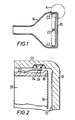
- a CRT has a faceplate 10 internally lined with a phosphor pattern 12 and the faceplate 10 has a flange 13 which is bonded to the envelope 14 of the tube.
- a shadow mask 16 is welded to a generally rectangular frame 20 within the tube adjacent the faceplate 10, and the frame 20 is mounted at four locations spaced around the frame to the flange 13 of the tube faceplate 10.
- a leaf spring 22 which is welded to the frame 20 extends alongside the faceplate flange 13, and a tapered spigot 24 welded to the free end of the leaf spring 22 projects radially outwardly into a socket 26 provided in the inner surface of the flange 13.
- the leaf spring 22 and the engagement of its spigot 24 with the respective socket 26 prevents movement of the frame 20 (i) longitudinally of the leaf spring (that is, towards and away from the faceplate 10) and (ii) laterally of the leaf spring (that is, into and out of the paper as seen in Figure 2).
- the lateral constraints provided by all four leaf springs 22 therefore prevent the frame 20 moving in its own plane.
- FIG. 3A shows detail of the socket 26 shown in Figure 2.
- a mounting element 28 which provides the socket 26 includes a dished element 30 which is bonded in a recess in the faceplate flange 13 so that it is flush with, slightly recessed below, or slightly raised above, the inner surface of the flange.
- the dished element 30 is formed of a material which matches that of the flange 13 in that it has a similar coefficient of expansion, whereby the dished element, flange and bond therebetween do not become substantially stressed upon changes of temperature.
- the dished element 30 may be formed of an alloy known as "Nilo 475". If however, the faceplate is of a ceramic material, the dished element may be formed of an alloy known as "Vacon 70". Both of these alloys are relatively soft.
- the socket 26 is formed in the base of a further dished element 32 which is disposed in and upside-down relative to the soft dished element 30.
- the rim of the further element 32 is welded to the base of the element 30 and the base of the further element 32 is flush with, or recessed slightly below, or raised slightly above the inner surface of the flange 13.
- the further dished element 32 is made of a hard material such as stainless steel hardened by heat treatment.
- the spigot 24 is simply provided by a frusto-conical lump 34 of hard material attached at its larger end to the free end of the leaf spring 22.
- the spigot Upon mating of the spigot 24 and socket 26, the spigot fully engages the socket partway along the length of the spigot due to the conical form of the spigot and the relative sizes of the spigot and socket.
- Figure 3B shows an alternative to the arrangement of Figure 3A, in which the hard element providing the socket 26 is an annular element 36 and is attached to the base of the soft dished element 30.
- Figures 4B and 4C show alternatives to the spigot arrangement.
- the spigot 24 is provided by a generally frusto-conical dished element 38 welded at its rim to the leaf spring 22, whereas in Figure 4C the spigot 24 is formed integrally with the leaf spring 22 to provide a generally frusto-conical projection 40.
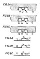
- FIGS 5A, 5B and 5C show modifications in which the spigot 24 is provided by a mounting element on the faceplate flange 13 and Figures 6A, 6B and 6C which show complementary socket-forming mounting elements provided on the leaf spring 22.
- the spigot 24 is provided by a dished element 42, similar to the element 38 in Figure 4B, welded to the soft alloy dished element 38.
- the spigot 24 of Figure 5B is formed by an integral portion 44 of the soft alloy dished element 38, in a somewhat similar fashion to the spigot 40 in Figure 4C.
- the spigot 24 is provided by a frusto-conical lump 46 attached to the soft alloy dished element 38, similar to the spigot 34 of Figure 4A.
- the top of the spigot may be level with, raised above or recessed below the surface of the flange 13.
- a socket 26 may be provided on the leaf spring 22 in (a) a dished element 48, for example of stainless steel, as shown in Figure 6A and similar to the element 32 of Figure 3A: (b) an integral portion 50 of the leaf spring 22, as shown in Figure 6B, or (c) an annular element 52,similar to the element 36 in Figure 3B, attached to the spring 22, as shown in Figure 6C.
- a dished element 48 for example of stainless steel
- the portion of the mounting element which forms the socket 26 is formed of a hard material, such as heat treated stainless steel.
- the spigot 24 is also of hard material, and this can be achieved in all of the spigot-providing arrangements illustrated except that of Figure 5B, where the spigot is of the same material as that which is bonded to the faceplate flange 13.
- the spigot is of a relatively soft material, upon wear of the spigot there is a tendency for the spigot to barrel or bulge and thus there is no substantial detrimental effect to the positiveness and stability of the location of the spigot and socket.
- the cross-section of the spigot and shape of the socket is preferably circular, but they may be a different shape, such as elliptical, square, rectangular or triangular. Furthermore, more than one spigot and socket arrangement may be formed at each mounting element. For convenience the socket is cylindrical, but it may alternatively be shaped and/or tapered complementarily to the spigot.
- the space occupied by the mounting arrangements described above is small.
- the mounting element on the tube is recessed into the wall of the tube to save space, and the clearance between the frame 20 and tube in the region of the leaf spring 22 need only be sufficient to enable the spigot and socket to be disengaged.
Abstract
A plurality of mountings for locating a shadow mask carrying frame in a colour cathode ray tube each comprise one mounting element (24, Figure 5A) bonded to the tube wall (13) and another mounting element (48, Figure 6A) connected to the frame, which together provide a spring-loaded spigot-and-socket connection. One feature is that the element (24) has a portion (38) bonded to the wall (13) of a compatible material and a second portion (42) of a hard material for low-wear. Another feature is that the element (24) provides the spigot (42) and has a recess therearound within the thickness of the wall (13) into which the other element (48) extends in order to save space.
Description
- This invention is concerned with colour cathode ray tubes.
- In particular, one aspect of this invention relates to colour cathode ray tubes of the type having a shadow mask carrying frame and a plurality of means arranged around the frame to mount the frame in the tube, each mounting means comprising a mounting element which is bonded to a wall of the tube and a mounting element connected to the frame, and the two mounting elements together providing a spring-loaded complementary spigot-and-socket connection.
- Such an arrangement is known. In the known arrangement, the mounting element which is bonded to the tube wall is made of a soft nickel-iron alloy, so as to have a similar coefficient to expansion to that of the tube. The material of the mounting element connected to the frame matches that of the mounting element bonded to the tube wall, with the intention of alleviating undesirable wear of the spigot. However, a disadvantage arises in that, since the mounting elements are both relatively soft, wear is still a problem and the arrangement is not very rigid.
- In accordance with the first aspect of the invention, the mounting element which is bonded to the tube wall comprises a first portion bonded to the wall of a material compatible with the material of the tube and a second portion providing the spigot or socket (as the case may be) which is secured to the first portion and which is of a hard material.
- In one arrangement, the spigot can be provided on the mounting element which is bonded to the tube, and the socket can be provided by the mounting element which is connected to the frame. In this case, a recess is preferably provided around the spigot within the thickness of the tube wall, the other mounting element extending into the recess. In an alternative arrangement, the spigot may be provided by the mounting element which is connected to the frame, and the socket can be provided by the mounting element which is bonded to the tube. In this case, the socket is preferably recessed within the thickness of the tube wall. By providing such recessing, the amount of space taken up by the mounting means is reduced.
- The first portion of the mounting element which is bonded to the tube wall preferably has a coefficient of expansion of the same order as that of the tube wall in order to provide the required compatibility with the tube.
- A second aspect of the present invention relates to a cathode ray tube of the type having a shadow mask carrying frame and a plurality of means arranged around the frame to mount the frame in the tube, each mounting means comprising a mounting element providing a spigot and secured to a wall of the tube and a mounting element providing a socket and connected to the frame so that the two mounting elements together provide a spring-loaded complementary spigot-and-socket connection.
- Such an arrangement is known, in which the spigot projects from the tube wall in order to be able to engage with the socket.
- In accordance with the second aspect of the invention, a recess is provided around the spigot within the thickness of the tube wall, and the other mounting element extends into the recess. Such recessing around the spigot and entry of the socket forming element into the recess reduces the amount of space taken up by the mounting means.
- In one arrangement, the spigoted mounting element is provided by a single member having a coefficient of expansion of the same order as that of the tube, in order to be compatible with the tube. However, in a preferred arrangement, the spigoted mounting element comprises a first member bonded to the tube and having a coefficient expansion of the same order as that of the tube and a second member joined to the first member and providing the spigot. In this case, the second member may be formed of a material which is harder than that of the first member. When used with a socket forming member also of a hard material, problems of wear are alleviated.
- With either aspect of the invention, each mounting element may be connected to the frame by a leaf spring having one end secured to the frame. Furthermore, each spigot is preferably tapered so as to be positively located by engagement with the mouth of the socket.
- There follows a description by way of example of an embodiment of the invention and some modifications thereto, reference being made to the drawings, in which:
- Figure 1 is a schematic side view of a CRT with the envelope and faceplate sectioned;
- Figure 2 is an enlarged schematic view showing detail of the portion marked "A" in Figure 1;
- Figures 3A and 3B are detail views of two versions of socket-type mounting element on the tube;
- Figure 4A, 4B and 4C are detailed views of three versions of spigot-type mounting element connected to the frame for engagement with either of the socket-type elements shown in Figures 3A and 3B;
- Figures 5A, 5B and 5C are detail views of three versions spigot-type mounting element on the tube; and
- Figures 6A, 6B and 6C are detail views of three versions of socket-type mounting element connected to the frame for engagement with any of the spigot-type elements shown in Figures 5A, 5B and 5C.
- Referring to Figures 1 and 2 of the drawings, a CRT has a
faceplate 10 internally lined with aphosphor pattern 12 and thefaceplate 10 has aflange 13 which is bonded to theenvelope 14 of the tube. Ashadow mask 16 is welded to a generallyrectangular frame 20 within the tube adjacent thefaceplate 10, and theframe 20 is mounted at four locations spaced around the frame to theflange 13 of thetube faceplate 10. At each such location, one of which is shown in Figure 2, aleaf spring 22 which is welded to theframe 20 extends alongside thefaceplate flange 13, and atapered spigot 24 welded to the free end of theleaf spring 22 projects radially outwardly into asocket 26 provided in the inner surface of theflange 13. - At each of the four mounting locations, the
leaf spring 22 and the engagement of itsspigot 24 with therespective socket 26 prevents movement of the frame 20 (i) longitudinally of the leaf spring (that is, towards and away from the faceplate 10) and (ii) laterally of the leaf spring (that is, into and out of the paper as seen in Figure 2). The lateral constraints provided by all fourleaf springs 22 therefore prevent theframe 20 moving in its own plane. - Reference is now made to Figure 3A, which shows detail of the
socket 26 shown in Figure 2. - A
mounting element 28 which provides thesocket 26 includes a dishedelement 30 which is bonded in a recess in thefaceplate flange 13 so that it is flush with, slightly recessed below, or slightly raised above, the inner surface of the flange. The dishedelement 30 is formed of a material which matches that of theflange 13 in that it has a similar coefficient of expansion, whereby the dished element, flange and bond therebetween do not become substantially stressed upon changes of temperature. In the case where the faceplate is made of glass, thedished element 30 may be formed of an alloy known as "Nilo 475". If however, the faceplate is of a ceramic material, the dished element may be formed of an alloy known as "Vacon 70". Both of these alloys are relatively soft. - In order to provide for a harder spigot-engaging portion of the
socket 26, thesocket 26 is formed in the base of a further dishedelement 32 which is disposed in and upside-down relative to the soft dishedelement 30. The rim of thefurther element 32 is welded to the base of theelement 30 and the base of thefurther element 32 is flush with, or recessed slightly below, or raised slightly above the inner surface of theflange 13. The further dishedelement 32 is made of a hard material such as stainless steel hardened by heat treatment. - Referring now to Figure 4A, detail is shown of the spigot in Figure 2. The
spigot 24 is simply provided by a frusto-conical lump 34 of hard material attached at its larger end to the free end of theleaf spring 22. - Upon mating of the
spigot 24 andsocket 26, the spigot fully engages the socket partway along the length of the spigot due to the conical form of the spigot and the relative sizes of the spigot and socket. - Figure 3B shows an alternative to the arrangement of Figure 3A, in which the hard element providing the
socket 26 is anannular element 36 and is attached to the base of the soft dishedelement 30. - Figures 4B and 4C show alternatives to the spigot arrangement. In Figure 4B, the
spigot 24 is provided by a generally frusto-conical dishedelement 38 welded at its rim to theleaf spring 22, whereas in Figure 4C thespigot 24 is formed integrally with theleaf spring 22 to provide a generally frusto-conical projection 40. - Reference is now made to Figures 5A, 5B and 5C which show modifications in which the
spigot 24 is provided by a mounting element on thefaceplate flange 13 and Figures 6A, 6B and 6C which show complementary socket-forming mounting elements provided on theleaf spring 22. - In Figure 5A, the
spigot 24 is provided by a dishedelement 42, similar to theelement 38 in Figure 4B, welded to the soft alloy dishedelement 38. Thespigot 24 of Figure 5B is formed by anintegral portion 44 of the soft alloy dishedelement 38, in a somewhat similar fashion to thespigot 40 in Figure 4C. In Figure 5C, thespigot 24 is provided by a frusto-conical lump 46 attached to the soft alloy dishedelement 38, similar to thespigot 34 of Figure 4A. In each of Figures 5A, 5B and 5C, the top of the spigot may be level with, raised above or recessed below the surface of theflange 13. - To complement the spigots shown in Figures 5A, 5B and 5C, a
socket 26 may be provided on theleaf spring 22 in (a) a dishedelement 48, for example of stainless steel, as shown in Figure 6A and similar to theelement 32 of Figure 3A: (b) anintegral portion 50 of theleaf spring 22, as shown in Figure 6B, or (c) an annular element 52,similar to theelement 36 in Figure 3B, attached to thespring 22, as shown in Figure 6C. - In all of the arrangements described above, the portion of the mounting element which forms the
socket 26 is formed of a hard material, such as heat treated stainless steel. Preferably, thespigot 24 is also of hard material, and this can be achieved in all of the spigot-providing arrangements illustrated except that of Figure 5B, where the spigot is of the same material as that which is bonded to thefaceplate flange 13. However, if the spigot is of a relatively soft material, upon wear of the spigot there is a tendency for the spigot to barrel or bulge and thus there is no substantial detrimental effect to the positiveness and stability of the location of the spigot and socket. - The cross-section of the spigot and shape of the socket is preferably circular, but they may be a different shape, such as elliptical, square, rectangular or triangular. Furthermore, more than one spigot and socket arrangement may be formed at each mounting element. For convenience the socket is cylindrical, but it may alternatively be shaped and/or tapered complementarily to the spigot.
- It will be noted that the space occupied by the mounting arrangements described above is small. The mounting element on the tube is recessed into the wall of the tube to save space, and the clearance between the
frame 20 and tube in the region of theleaf spring 22 need only be sufficient to enable the spigot and socket to be disengaged.
Claims (12)
1. A colour cathode ray tube having a shadow mask carrying frame (20) and a plurality of means arranged around the frame to mount the frame in the tube, each mounting means comprising a mounting element which is bonded to a wall (13) of the tube and a mounting element connected to the frame, and the two mounting elements together providing a spring-loaded complementary spigot-and-socket connection, characterised in that the mounting element which is bonded to the tube wall comprises a first portion (30;38) bonded to the wall of a material compatible with the material of the tube and a second portion (32;36;42;46) providing the spigot (24) or socket (26) (as the case may be) which is secured to the first portion and which is of a hard material.
2. A cathode ray tube as claimed in claim 1, characterised in that the spigot is provided on the mounting element which is bonded to the tube and the socket is provided by the mounting element which is connected to the frame (Figures 4A/5C and 6A/6B/6C).
3. A cathode ray tube as claimed in claim 2, characterised in that a recess is provided around the spigot within the thickness of the tube wall (13) and the other mounting element (48;50;52) extends into the recess.
4. A cathode ray tube as claimed in claim 1, characterised in that the spigot is provided by the mounting element which is connected to the frame, and the socket is provided by the mounting element which is bonded to the tube (Figures 3A/3B and 4A/4B/4C).
5. A cathode ray tube as claimed in claim 4, characterised in that the socket (26) is recessed within the thickness of the tube wall (13).
6. A cathode ray tube as claimed in any preceding claim, characterised in that the first portion (30;38) of the mounting element which is bonded to the tube wall has a coefficient of expansion of the same order as that of the tube wall.
7. A colour cathode ray tube having a shadow mask carrying frame (20) and a plurality of means arranged around the frame to mount the frame in the tube, each mounting means comprising a mounting element providing a spigot (42;44;46) and secured to a wall (13) of the tube and a mounting element providing a socket (26) and connected to the frame so that the two mounting elements together provide a spring-loaded complementary spigot-and-socket connection, characterised in that a recess is provided around the spigot within the thickness of the tube wall and the other mounting element extends into the recess.
8. A cathode ray tube as claimed in claim 7, characterised in that the spigoted mounting element is provided by a single member having a coefficient of expansion of the same order as that of the tube (Figure 5B).
9. A cathode ray tube as claimed in claim 7, characterised in that the spigoted mounting element comprises a first member (38) bonded to the tube and having a coefficient of expansion of the same order as that of the tube and a second member (42;46) joined to the first member and providing the spigot (Figures 5A/5C).
10. A cathode ray tube as claimed in claim 9, characterised in that the second member is harder than the first member.
11. A cathode ray tube as claimed in any preceding claim, characterised in that each mounting element which is connected to the frame includes a leaf spring (22) having one end secured to the frame.
12. A colour cathode ray tube as claimed in any preceding claim characterised in that the spigot is tapered.
Applications Claiming Priority (2)
| Application Number | Priority Date | Filing Date | Title |
|---|---|---|---|
| GB8609139 | 1986-04-15 | ||
| GB868609139A GB8609139D0 (en) | 1986-04-15 | 1986-04-15 | Colour cathode ray tubes |
Publications (1)
| Publication Number | Publication Date |
|---|---|
| EP0242206A1 true EP0242206A1 (en) | 1987-10-21 |
Family
ID=10596197
Family Applications (1)
| Application Number | Title | Priority Date | Filing Date |
|---|---|---|---|
| EP87303340A Ceased EP0242206A1 (en) | 1986-04-15 | 1987-04-15 | Colour cathode ray tubes |
Country Status (4)
| Country | Link |
|---|---|
| US (1) | US4804880A (en) |
| EP (1) | EP0242206A1 (en) |
| JP (1) | JPS62254347A (en) |
| GB (1) | GB8609139D0 (en) |
Cited By (2)
| Publication number | Priority date | Publication date | Assignee | Title |
|---|---|---|---|---|
| GB2190538B (en) * | 1986-05-14 | 1990-07-25 | Sony Corp | Colour cathode-ray tubes |
| GB2228364A (en) * | 1988-12-31 | 1990-08-22 | Samsung Electronic Devices | Support for tensioned shadow mask of flat panel colour tube |
Families Citing this family (2)
| Publication number | Priority date | Publication date | Assignee | Title |
|---|---|---|---|---|
| JP3097679B2 (en) * | 1998-11-11 | 2000-10-10 | 関西日本電気株式会社 | Color cathode ray tube |
| JP2002313259A (en) * | 2001-04-11 | 2002-10-25 | Nippon Electric Glass Co Ltd | Glass panel for color television picture tube |
Citations (2)
| Publication number | Priority date | Publication date | Assignee | Title |
|---|---|---|---|---|
| GB1304567A (en) * | 1969-09-06 | 1973-01-24 | ||
| GB2129208A (en) * | 1982-10-18 | 1984-05-10 | Rca Corp | Color selection electrode mounting structure |
Family Cites Families (1)
| Publication number | Priority date | Publication date | Assignee | Title |
|---|---|---|---|---|
| NL6709114A (en) * | 1967-06-30 | 1968-12-31 |
-
1986
- 1986-04-15 GB GB868609139A patent/GB8609139D0/en active Pending
-
1987
- 1987-04-14 JP JP62091844A patent/JPS62254347A/en active Pending
- 1987-04-14 US US07/038,233 patent/US4804880A/en not_active Expired - Fee Related
- 1987-04-15 EP EP87303340A patent/EP0242206A1/en not_active Ceased
Patent Citations (2)
| Publication number | Priority date | Publication date | Assignee | Title |
|---|---|---|---|---|
| GB1304567A (en) * | 1969-09-06 | 1973-01-24 | ||
| GB2129208A (en) * | 1982-10-18 | 1984-05-10 | Rca Corp | Color selection electrode mounting structure |
Non-Patent Citations (2)
| Title |
|---|
| PATENT ABSTRACTS OF JAPAN, unexamined applications, E section, vol. 3, no. 61, May 26, 1979 THE PATENT OFFICE JAPANESE GOVERNMENT page 90 E 113; & JP-A-54 040 563 (MITSUBISHI) * * |
| PATENT ABSTRACTS OF JAPAN, unexamined applications, E section, vol. 3, no. 9, January 26, 1979 THE PATENT OFFICE JAPANESE GOVERNMENT page 18 E 86; & JP-A-53 135 566 (HITACHI) * |
Cited By (2)
| Publication number | Priority date | Publication date | Assignee | Title |
|---|---|---|---|---|
| GB2190538B (en) * | 1986-05-14 | 1990-07-25 | Sony Corp | Colour cathode-ray tubes |
| GB2228364A (en) * | 1988-12-31 | 1990-08-22 | Samsung Electronic Devices | Support for tensioned shadow mask of flat panel colour tube |
Also Published As
| Publication number | Publication date |
|---|---|
| JPS62254347A (en) | 1987-11-06 |
| US4804880A (en) | 1989-02-14 |
| GB8609139D0 (en) | 1986-05-21 |
Similar Documents
| Publication | Publication Date | Title |
|---|---|---|
| FI57331B (en) | FAERGTELEVISIONSROER MED REKTANGULAER FAERGVAELJARELEKTROD OCH BILDSKAERM AV GLAS FOER ETT DYLIKT ROER | |
| EP0242206A1 (en) | Colour cathode ray tubes | |
| US4300071A (en) | Four-corner shadow mask suspension system for television cathode ray tubes | |
| KR900002898B1 (en) | Color cathode ray tube | |
| EP0146926A2 (en) | Shadow mask type color picture tube | |
| US5025192A (en) | End base construction for a discharge lamp | |
| JP2004006411A (en) | Cathode-ray tube and glass funnel therefor | |
| EP0053782A1 (en) | A projection unit including a glass reflector | |
| KR100220994B1 (en) | Separation type and one body type convergense compensation device of deflection yoke | |
| EP0521715B1 (en) | Gas laser tube | |
| US6545400B2 (en) | Shadow mask type color cathode ray tube having a shadow mask with curls thereof reduced | |
| US5247224A (en) | Color cathode ray tube shadow mask assembly | |
| KR930008495B1 (en) | Cathode supporting structure for color cathode-ray tube | |
| GB2092821A (en) | Support frame and electron shield for a colour tube shadow mask | |
| GB2384112A (en) | Glass bulb for cathode ray tube and nathode ray tube | |
| JP2529956B2 (en) | Color picture tube | |
| JP3221010B2 (en) | Cathode ray tube | |
| US5510671A (en) | Inwardly convex vacuum envelope | |
| US6653774B2 (en) | Funnel for cathode ray tube | |
| JPH029497Y2 (en) | ||
| KR940006547Y1 (en) | Electron gun for c-crt | |
| KR0131922Y1 (en) | Molding plate of electron gun electrode | |
| KR0122855Y1 (en) | Stem of electron gun for braun tube | |
| EP0895022A2 (en) | Base for compact fluorescent lamp | |
| KR930001181B1 (en) | Cathode structure of cathode-ray tube |
Legal Events
| Date | Code | Title | Description |
|---|---|---|---|
| PUAI | Public reference made under article 153(3) epc to a published international application that has entered the european phase |
Free format text: ORIGINAL CODE: 0009012 |
|
| AK | Designated contracting states |
Kind code of ref document: A1 Designated state(s): DE FR GB NL |
|
| 17P | Request for examination filed |
Effective date: 19880420 |
|
| 17Q | First examination report despatched |
Effective date: 19890531 |
|
| STAA | Information on the status of an ep patent application or granted ep patent |
Free format text: STATUS: THE APPLICATION HAS BEEN REFUSED |
|
| 18R | Application refused |
Effective date: 19900506 |
|
| RIN1 | Information on inventor provided before grant (corrected) |
Inventor name: KAVANAGH, MARTIN |