EP0241355B1 - Glasscheibenbiegevorrichtung - Google Patents
Glasscheibenbiegevorrichtung Download PDFInfo
- Publication number
- EP0241355B1 EP0241355B1 EP87400716A EP87400716A EP0241355B1 EP 0241355 B1 EP0241355 B1 EP 0241355B1 EP 87400716 A EP87400716 A EP 87400716A EP 87400716 A EP87400716 A EP 87400716A EP 0241355 B1 EP0241355 B1 EP 0241355B1
- Authority
- EP
- European Patent Office
- Prior art keywords
- glass
- glass sheet
- mould
- suction
- bending
- Prior art date
- Legal status (The legal status is an assumption and is not a legal conclusion. Google has not performed a legal analysis and makes no representation as to the accuracy of the status listed.)
- Expired
Links
Images

Classifications
-
- C—CHEMISTRY; METALLURGY
- C03—GLASS; MINERAL OR SLAG WOOL
- C03B—MANUFACTURE, SHAPING, OR SUPPLEMENTARY PROCESSES
- C03B23/00—Re-forming shaped glass
- C03B23/02—Re-forming glass sheets
- C03B23/023—Re-forming glass sheets by bending
- C03B23/03—Re-forming glass sheets by bending by press-bending between shaping moulds
-
- C—CHEMISTRY; METALLURGY
- C03—GLASS; MINERAL OR SLAG WOOL
- C03B—MANUFACTURE, SHAPING, OR SUPPLEMENTARY PROCESSES
- C03B23/00—Re-forming shaped glass
- C03B23/02—Re-forming glass sheets
- C03B23/023—Re-forming glass sheets by bending
- C03B23/035—Re-forming glass sheets by bending using a gas cushion or by changing gas pressure, e.g. by applying vacuum or blowing for supporting the glass while bending
- C03B23/0352—Re-forming glass sheets by bending using a gas cushion or by changing gas pressure, e.g. by applying vacuum or blowing for supporting the glass while bending by suction or blowing out for providing the deformation force to bend the glass sheet
- C03B23/0357—Re-forming glass sheets by bending using a gas cushion or by changing gas pressure, e.g. by applying vacuum or blowing for supporting the glass while bending by suction or blowing out for providing the deformation force to bend the glass sheet by suction without blowing, e.g. with vacuum or by venturi effect
-
- C—CHEMISTRY; METALLURGY
- C03—GLASS; MINERAL OR SLAG WOOL
- C03B—MANUFACTURE, SHAPING, OR SUPPLEMENTARY PROCESSES
- C03B23/00—Re-forming shaped glass
- C03B23/02—Re-forming glass sheets
- C03B23/023—Re-forming glass sheets by bending
- C03B23/03—Re-forming glass sheets by bending by press-bending between shaping moulds
- C03B23/0302—Re-forming glass sheets by bending by press-bending between shaping moulds between opposing full-face shaping moulds
-
- C—CHEMISTRY; METALLURGY
- C03—GLASS; MINERAL OR SLAG WOOL
- C03B—MANUFACTURE, SHAPING, OR SUPPLEMENTARY PROCESSES
- C03B23/00—Re-forming shaped glass
- C03B23/02—Re-forming glass sheets
- C03B23/023—Re-forming glass sheets by bending
- C03B23/035—Re-forming glass sheets by bending using a gas cushion or by changing gas pressure, e.g. by applying vacuum or blowing for supporting the glass while bending
Definitions
- the present invention relates to an improvement of the techniques for forming flat glass and more specifically to those techniques, according to which the glass sheets are shaped by application against a form of bending using forces of a pneumatic nature.
- the forming takes place either at the time and after the installation of the glass sheet on the recovery frame which is then advantageously constituted by an open ring whose outline corresponds to the outline which it is desired to impart to the sheet of glass, the bending then taking place under the effect of the forces of gravity and inertia, that is to say when the glass sheet is taken over by the transfer member which then comprises a higher form of bending whose curvature corresponds to that of the shaped glass sheet, or again by a combination of the two cases mentioned above.
- the forming methods by applying the glass sheet against a higher bending form are particularly advantageous, because they allow better control of the deformation of the glass in its central part, while perfectly respecting the shape desired for the contour of the glass. .
- the glass sheet is conveyed in a reheating furnace, in a horizontal position, by a conveyor of the roller bed type which extends downstream of the oven to a bending station. There, the glass sheet is immobilized then transferred vertically, by a suction due to a depression created around the periphery of the sheet, to a superior bending shape, curved, non-perforated, against which it is applied to be shaped , depending on the main curvature desired.
- the vacuum is obtained by placing the upper bending form in a bottomless box or skirt, linked to suction means, and whose inner contour is slightly larger than that of the glass sheet while the contour of the the upper bending shape is slightly smaller than this.
- an additional curvature is then imparted to the glass, for example by pressing.
- the present invention proposes to improve the technique developed above in order to reduce its drawbacks, while retaining its advantages.
- the glass sheet is lifted and pressed against an upper form of bending by a depression which is exerted on the periphery and in the vicinity of the periphery of the glass sheet.
- the lower face of the upper bending form is placed at least partly outside the vacuum box.
- a device comprising a depression box in which is placed an upper bending shape of dimensions smaller than that of the glass sheet to be conformed and the lower face of which, against which the glass sheet is applied, is situated outside the vacuum box, that is to say that the lower limit of the side walls of the box is located above the lower limit of the bending shape.
- the change of upper shape can be carried out without simultaneous replacement of the vacuum box because the upper shape is located according to the invention, at the outside of the vacuum box.
- the upper bending form is constructed of a light material, for example of refractory steel which greatly facilitates its handling.
- the upper form being advantageously mounted not integral with the vacuum box, the only replacement of the upper form depending on the dimensions of the glazing is possible inside the heated forming enclosure, with a minimum of heat losses. and in a particularly short period of time.
- the upper form is connected to a device for supplying hot air, possibly under pressure.
- a protective air cushion is thus formed between the upper form and the glass sheet.
- a preferred embodiment of the invention makes it easier to obtain forms of glazing which are difficult to obtain, requiring additional forming after forming by application against the upper form.
- the box is surrounded by a concentric skirt movable in a vertical direction.
- This concentric skirt is such that immediately before the take-off of the glass sheet, it determines a provisional box which is of dimensions slightly greater than the glass sheet; thus the mobility of the skirt makes it possible to easily introduce a form of pressing into the forming unit and moreover it reduces the suction power required.
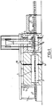
- the forming unit shown in FIG. 1 successively comprises a loading section 1 for the glass sheets 2, a glass heating furnace 3 and a glass forming cell 4.
- the oven 3 the opening of which is closed by a series of flexible curtains 5, 6 intended to avoid thermal shocks in the oven when the glass is loaded, is traversed by a conveyor 7 formed for example by a bed of rollers 8 glassy silica sheathed with refractory fabric.
- This tunnel type oven has two series 9, 10 of electric resistors facing each other, placed on either side of the conveyor and whose temperatures vary according to the longitudinal and transverse position in the oven, so as to control very precisely the heating of the glass.
- Such an oven allows very good control of the heating of the glass up to a temperature allowing them to be formed, generally of the order of 630-650 ° C.
- the glass sheet Downstream of the furnace, the glass sheet enters the forming unit 4 proper, its arrival being identified using optical detectors, of the photoelectric type, possibly combined with mechanical detectors, displaced by the glass sheet.
- optical detectors of the photoelectric type, possibly combined with mechanical detectors, displaced by the glass sheet.
- mechanical detectors are for example described in French patent application 85.13801.
- Glass detection enables simultaneous stopping of the roller drive of the conveyor located under the forming device. At this time the glass sheet is lifted under the effect of a powerful suction and is pressed against the upper bending shape 11 which it then marries the curvature.
- the assembly constituted by the glass sheet and the upper bending form, as well as elements making it possible to create the suction, is then lifted so as to leave sufficient space for the introduction of a carriage 12 for recovering the glass. .
- the sheet formed is finally deposited on said carriage which leads it by rails arranged on either side of the conveyor to the next glass processing cell.
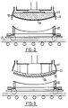
- FIG. 2 shows a device of the type described in patent FR 2 085 464, in order to better show the differences with the characteristics of the invention forming the subject of the present application.
- a bottomless box 22 forms a "skirt" around a form 23.
- the box has strictly the same geometric shape as a glass sheet 24 but slightly larger dimensions.
- the bending shape 23 has dimensions slightly smaller than those of the glass sheet 24, there remains a peripheral space between the sheet and the bottomless box through which a lateral leakage "1" takes place, this which creates a depression which presses the glass sheet against the form 23, of which it follows the shape before being recovered by the carriage moved on the rails 21.
- Any change in the dimensions of the glass sheet requires a modification shape and box, and on the other hand, any error in the centering of the glass sheets leads to a marking of the sheet which has struck the side walls of the vacuum box.
- the upper bending form is easier to access, especially if it is also constructed from a relatively light material, but resistant without deformation to the working temperatures required here, such as refractory steel.
- a refractory steel also has, compared to the refractory cements recommended by patent FR 2 085 464, the advantage of a much greater thermal conductivity and therefore of a much greater heating rate. and cooling, speed which is found in the times of interruption of the operation of the forming unit for changes of higher bending shapes.
- the suction box can then be constructed in two independent parts, the skirt itself and a suction chamber, parts then provided with dismantling means. More preferably, the skirt of the suction box is provided with two studs 33, made of metal or Teflon for example, on which abuts the front edge of the glass sheet which is thus repositioned correctly along the axis of the conveyor.
- the device of Figure 3 can receive further improvements.
- the upper sheet can be provided with a series of spacers against which the glass sheet is supported. If the latter is partly enamelled, these studs are advantageously arranged so that no contact occurs between the studs and the enamel, which simultaneously limits the risks of abrasion of the enamel itself and the deterioration by the enamel of the contact surface with the glass of the upper bending form, which on the one hand limits the risks of abrasion of the enamel, and on the other hand eliminates the interruptions due to the replacement of the fabric or refractory paper generally used.
- the spacers are eliminated and a hot air cushion is substituted for them, the latter solution being preferable from the point of view of optical quality.
- any contact between the glass and the upper bending form is prohibited, which is particularly advantageous for the forming of glass sheets having an enamelled decoration on an entire face or at least in the central part thereof.
- This implementation is shown diagrammatically in FIG. 4, its principle consists in isolating the upper bending shape 25 from the suction box 27 placed under vacuum using the horn 28 by putting under pressure a chamber 29 located above above the upper bending form 25 and in communication with the lower face thereof;
- a chamber 29 located above above the upper bending form 25 and in communication with the lower face thereof;
- the pressure chamber 29 can, depending the cases be supplied with the aid of a compressor or simply be connected to a pipe 30 leading to the outside of the box 27 in the forming cell, the depression created moreover for the suction of the glass sheet sufficient to create a gas call and the pressure necessary to build up the air cushion.
- the upper bending shape is curved at least I ⁇ ngitudinally and that its deflection is equal to that of the main curvature that it is desired to impart to the glazing after bending, which therefore corresponds to glass forming essentially by plating against a form .
- the glass exhibits characteristics which cause this upper shape to overhang in order to obtain the desired main curvature in the final analysis.
- the embodiments of the invention described above are well suited for obtaining curved glazing with a large radius of curvature.
- the main bending provided by the application against the upper shape, must be supplemented by a complementary bending operation, preferably by pressing as other usual means of forming can also be used.
- a complementary bending operation preferably by pressing as other usual means of forming can also be used.
- the skirt 30 is of very reduced dimensions and is lined with walls 31 movable vertically. In the low position, these walls reach a level very slightly higher than that of the glass on the conveyor. The depression thus occurs just at the periphery of the glass which facilitates the flight of the sheet.
- the height mobility of the walls makes it possible to lift them when the pressing form is introduced, without having to raise the upper bending form to a too high height.
- the walls 31 carry at their lower end tabs 32 which bear against the edges of the pressing form at the time of recovery of the sheet and during the pressing operation if the upper form is also used as a counter-form of pressing.
Landscapes
- Chemical & Material Sciences (AREA)
- Engineering & Computer Science (AREA)
- Materials Engineering (AREA)
- Organic Chemistry (AREA)
- Re-Forming, After-Treatment, Cutting And Transporting Of Glass Products (AREA)
Claims (10)
Applications Claiming Priority (2)
| Application Number | Priority Date | Filing Date | Title |
|---|---|---|---|
| FR8604962 | 1986-04-08 | ||
| FR8604962A FR2596751B1 (fr) | 1986-04-08 | 1986-04-08 | Dispositif de formage du verre |
Publications (2)
| Publication Number | Publication Date |
|---|---|
| EP0241355A1 EP0241355A1 (de) | 1987-10-14 |
| EP0241355B1 true EP0241355B1 (de) | 1989-07-19 |
Family
ID=9333986
Family Applications (1)
| Application Number | Title | Priority Date | Filing Date |
|---|---|---|---|
| EP87400716A Expired EP0241355B1 (de) | 1986-04-08 | 1987-04-01 | Glasscheibenbiegevorrichtung |
Country Status (8)
| Country | Link |
|---|---|
| US (1) | US4813993A (de) |
| EP (1) | EP0241355B1 (de) |
| JP (1) | JP2511025B2 (de) |
| KR (1) | KR950000623B1 (de) |
| BR (1) | BR8701590A (de) |
| DE (1) | DE3760331D1 (de) |
| FI (1) | FI82027C (de) |
| FR (1) | FR2596751B1 (de) |
Cited By (2)
| Publication number | Priority date | Publication date | Assignee | Title |
|---|---|---|---|---|
| DE19848373A1 (de) * | 1998-10-21 | 2000-04-27 | Sekurit Saint Gobain Deutsch | Verfahren und Vorrichtung zum Biegen von Glasscheiben mit einer flächigen Biegeform |
| EP2412682A1 (de) | 2010-07-29 | 2012-02-01 | Saint-Gobain Glass France | Verfahren und Vorrichtung zum Biegen von Glasscheiben |
Families Citing this family (28)
| Publication number | Priority date | Publication date | Assignee | Title |
|---|---|---|---|---|
| FR2601667B1 (fr) * | 1986-07-16 | 1988-09-16 | Saint Gobain Vitrage | Positionnement des plaques de verre en vue de leur bombage |
| US4767437A (en) * | 1987-03-25 | 1988-08-30 | Ppg Industries, Inc. | Horizontal press bending using a splitting vacuum/pressure pickup |
| FR2621906B1 (fr) * | 1987-10-14 | 1990-01-26 | Saint Gobain Vitrage | Amelioration de la trempe du verre |
| US5183491A (en) * | 1987-10-14 | 1993-02-02 | Saint-Gobain Recherche | Material for the tempering of glass |
| US4877437A (en) * | 1988-04-29 | 1989-10-31 | Glasstech International L.P. | Vacuum platen for sharp bends |
| US5213601A (en) * | 1988-12-21 | 1993-05-25 | Saint-Gobain Vitrage International | Method and apparatus for producing curved panes having a two-level curving station |
| AU635723B2 (en) * | 1988-12-21 | 1993-04-01 | Saint-Gobain Vitrage International | Production line for curved panes |
| FR2644776B1 (fr) * | 1989-03-24 | 1991-05-31 | Saint Gobain Vitrage | Positionnement d'une feuille de verre par rapport a des outils de bombage et/ou d'autres traitements thermiques |
| US5268016A (en) * | 1989-07-18 | 1993-12-07 | Saint-Gobain Vitrage International | Apparatus for obtaining cambered and/or glazed glass sheets |
| FR2649971B1 (fr) * | 1989-07-18 | 1993-07-16 | Saint Gobain Vitrage Int | Procede et dispositif de bombage de feuilles de verre |
| FR2662686B1 (fr) * | 1990-06-01 | 1992-08-21 | Saint Gobain Vitrage Int | Procede et dispositif de bombage de feuilles de verre. |
| FR2680777B1 (fr) * | 1991-08-27 | 1993-11-12 | Saint Gobain Vitrage Internal | Dispositif de bombage de feuilles de verre. |
| DE4337559C1 (de) * | 1993-11-04 | 1995-03-23 | Ver Glaswerke Gmbh | Verfahren zum paarweisen Biegen von Glasscheiben |
| JP3925042B2 (ja) * | 2000-06-15 | 2007-06-06 | 坂東機工株式会社 | ガラス板の加工方法及びその装置 |
| US7975509B2 (en) * | 2007-06-27 | 2011-07-12 | Pilkington North America, Inc. | Glass bending process |
| EP2463248A1 (de) * | 2010-12-13 | 2012-06-13 | Saint-Gobain Glass France | Verfahren und Vorrichtung zum Biegen von Scheiben |
| US8573005B2 (en) * | 2011-02-24 | 2013-11-05 | Corning Incorporated | Apparatus and method for mass producing 3D articles from 2D glass-containing sheets |
| CN102849930A (zh) * | 2012-09-06 | 2013-01-02 | 南京云海汽车玻璃设备制造有限公司 | 一种汽车前挡玻璃节能吸模高速炉 |
| EP3313792A1 (de) | 2015-06-26 | 2018-05-02 | Corning Incorporated | Vorrichtung und verfahren zur aufbereitung eines blattmaterials |
| RU2677509C1 (ru) * | 2015-08-18 | 2019-01-17 | Сэн-Гобэн Гласс Франс | Устройство и способ моллирования стекла с использованием вентилятора |
| CN109416480B (zh) | 2016-07-05 | 2022-08-12 | 康宁公司 | 冷成形玻璃制品和其组装工艺 |
| JP2020518495A (ja) | 2017-01-03 | 2020-06-25 | コーニング インコーポレイテッド | 湾曲したカバーガラスとディスプレイまたはタッチパネルを有する乗り物内装システムおよびその形成方法 |
| CN115602068A (zh) | 2017-09-12 | 2023-01-13 | 康宁公司(Us) | 用于装饰玻璃上的包括触摸面板的显示器的死前端及相关方法 |
| US11065960B2 (en) | 2017-09-13 | 2021-07-20 | Corning Incorporated | Curved vehicle displays |
| CN111656254B (zh) * | 2017-11-30 | 2023-06-02 | 康宁公司 | 用于真空成形非球面镜的系统与方法 |
| FI20185664A1 (fi) * | 2018-07-31 | 2020-02-01 | Taifin Glass Machinery Oy | Menetelmä laitteessa lasilevyjen taivuttamiseksi ja laite lasilevyjen taivuttamiseksi |
| US11772361B2 (en) | 2020-04-02 | 2023-10-03 | Corning Incorporated | Curved glass constructions and methods for forming same |
| CN115417604B (zh) * | 2022-08-30 | 2024-01-02 | 维达力实业(深圳)有限公司 | 玻璃表面加工模具及玻璃表面加工方法 |
Family Cites Families (6)
| Publication number | Priority date | Publication date | Assignee | Title |
|---|---|---|---|---|
| FR2085464B1 (de) * | 1970-04-23 | 1974-08-09 | Saint Gobain Pont A Mousson | |
| JPS5243855A (en) * | 1975-10-06 | 1977-04-06 | Nitto Electric Ind Co Ltd | Thermosetting resin compositions |
| CA1120725A (en) * | 1978-01-25 | 1982-03-30 | Norman C. Nitschke | Apparatus for bending and tempering glass |
| CA1120726A (en) * | 1978-05-01 | 1982-03-30 | Harold A. Mcmaster | Apparatus and method for bending glass |
| FR2567508B1 (fr) * | 1984-07-13 | 1986-11-14 | Saint Gobain Vitrage | Procede et dispositif pour le bombage de plaques de verre en position horizontale |
| US4615724A (en) * | 1984-11-23 | 1986-10-07 | Glasstech, Inc. | Glass sheet forming system including topside transfer apparatus |
-
1986
- 1986-04-08 FR FR8604962A patent/FR2596751B1/fr not_active Expired
-
1987
- 1987-04-01 EP EP87400716A patent/EP0241355B1/de not_active Expired
- 1987-04-01 DE DE8787400716T patent/DE3760331D1/de not_active Expired
- 1987-04-03 US US07/033,797 patent/US4813993A/en not_active Expired - Lifetime
- 1987-04-06 BR BR8701590A patent/BR8701590A/pt not_active IP Right Cessation
- 1987-04-07 JP JP62083935A patent/JP2511025B2/ja not_active Expired - Fee Related
- 1987-04-07 FI FI871523A patent/FI82027C/fi not_active IP Right Cessation
- 1987-04-08 KR KR1019870003320A patent/KR950000623B1/ko not_active IP Right Cessation
Cited By (3)
| Publication number | Priority date | Publication date | Assignee | Title |
|---|---|---|---|---|
| DE19848373A1 (de) * | 1998-10-21 | 2000-04-27 | Sekurit Saint Gobain Deutsch | Verfahren und Vorrichtung zum Biegen von Glasscheiben mit einer flächigen Biegeform |
| DE19848373C2 (de) * | 1998-10-21 | 2000-12-07 | Sekurit Saint Gobain Deutsch | Verfahren und Vorrichtung zum Biegen von Glasscheiben mit einer flächigen Biegeform |
| EP2412682A1 (de) | 2010-07-29 | 2012-02-01 | Saint-Gobain Glass France | Verfahren und Vorrichtung zum Biegen von Glasscheiben |
Also Published As
| Publication number | Publication date |
|---|---|
| JP2511025B2 (ja) | 1996-06-26 |
| FI871523A (fi) | 1987-10-09 |
| FI82027B (fi) | 1990-09-28 |
| FI871523A0 (fi) | 1987-04-07 |
| KR950000623B1 (ko) | 1995-01-26 |
| KR870009953A (ko) | 1987-11-30 |
| FI82027C (fi) | 1991-01-10 |
| US4813993A (en) | 1989-03-21 |
| FR2596751B1 (fr) | 1988-06-03 |
| JPS62241839A (ja) | 1987-10-22 |
| EP0241355A1 (de) | 1987-10-14 |
| DE3760331D1 (en) | 1989-08-24 |
| BR8701590A (pt) | 1988-01-26 |
| FR2596751A1 (fr) | 1987-10-09 |
Similar Documents
| Publication | Publication Date | Title |
|---|---|---|
| EP0241355B1 (de) | Glasscheibenbiegevorrichtung | |
| EP0290346B1 (de) | Verfahren und Vorrichtung zum Biegen von Glasscheiben | |
| EP1836137B1 (de) | Glasbiegungs- und glaskühlungsverfahren und vorrichtung mit zwei trägerzügen | |
| EP0556103B1 (de) | Vorrichtung zum Biegen von Windschutzscheiben | |
| EP1611064B1 (de) | Verfahren zum biegen von glasscheiben durch pressen und saugen | |
| EP0169770B1 (de) | Verfahren und Vorrichtung zum Biegen von Glasscheiben in horizontaler Lage | |
| EP0404676B1 (de) | Verfahren und Vorrichtung zum Biegen und Härten durch Kontakt | |
| EP1611062B1 (de) | Verfahren und vorrichtung zum biegen von glasscheiben | |
| BE897061A (fr) | Support pour feuilles de verre chaudes de contour irregulier avant courbure | |
| FR2468557A1 (fr) | Dispositif d'alignement des moules pour installation de faconnage de feuilles de verre suivant des formes compliquees | |
| EP3548441B1 (de) | Biegen von dünnglas | |
| EP0240418A1 (de) | Verfahren und Vorrichtung zum Formen von Glas | |
| EP0459898B1 (de) | Verfahren und Vorrichtung zum Biegen von Glasscheiben | |
| FR2465692A1 (fr) | Procede et dispositif de faconnage de feuilles de verre a l'aide de moules de formes differentes | |
| EP0272962B1 (de) | Verfahren und Vorrichtung zum Biegen einer Glasscheibe | |
| FR2693452A1 (fr) | Procédé et dispositif pour supporter et transférer des feuilles de verre dans une cellule de formage. | |
| FR2516502A1 (fr) | Procede et dispositif pour extraire des feuilles de verre cintrees et trempees d'un poste de refroidissement | |
| EP0299869B1 (de) | Biegen von Glasscheiben | |
| EP0409695B1 (de) | Verfahren und Vorrichtung zum Herstellen von gebogenen oder/und emaillierten Glasscheiben | |
| EP0375535B1 (de) | Fertigungsstrasse für gebogene Glasscheiben | |
| EP0463971B1 (de) | Verfahren und Vorrichtung zum Biegen und Härten von Glasscheiben | |
| FR2660302A1 (fr) | Installation pour le chauffage, le formage et la trempe de feuilles de verre. | |
| EP0471620B1 (de) | Verfahren und Vorrichtung zum Biegen von Glasscheiben | |
| EP0324690B1 (de) | Verfahren und Vorrichtung zum Biegen und Härten von Glasplatten | |
| FR2587309A1 (fr) | Dispositif de prehension et de transfert des feuilles de verre apres leur trempe thermique. |
Legal Events
| Date | Code | Title | Description |
|---|---|---|---|
| PUAI | Public reference made under article 153(3) epc to a published international application that has entered the european phase |
Free format text: ORIGINAL CODE: 0009012 |
|
| AK | Designated contracting states |
Kind code of ref document: A1 Designated state(s): BE CH DE ES FR GB IT LI SE |
|
| 17P | Request for examination filed |
Effective date: 19870929 |
|
| 17Q | First examination report despatched |
Effective date: 19880428 |
|
| GRAA | (expected) grant |
Free format text: ORIGINAL CODE: 0009210 |
|
| AK | Designated contracting states |
Kind code of ref document: B1 Designated state(s): BE CH DE ES FR GB IT LI SE |
|
| REF | Corresponds to: |
Ref document number: 3760331 Country of ref document: DE Date of ref document: 19890824 |
|
| ITF | It: translation for a ep patent filed |
Owner name: DR. ING. A. RACHELI & C. |
|
| PG25 | Lapsed in a contracting state [announced via postgrant information from national office to epo] |
Ref country code: ES Free format text: LAPSE BECAUSE OF FAILURE TO SUBMIT A TRANSLATION OF THE DESCRIPTION OR TO PAY THE FEE WITHIN THE PRESCRIBED TIME-LIMIT Effective date: 19891030 |
|
| GBT | Gb: translation of ep patent filed (gb section 77(6)(a)/1977) | ||
| RAP4 | Party data changed (patent owner data changed or rights of a patent transferred) |
Owner name: SAINT GOBAIN VITRAGE INTERNATIONAL |
|
| PLBE | No opposition filed within time limit |
Free format text: ORIGINAL CODE: 0009261 |
|
| STAA | Information on the status of an ep patent application or granted ep patent |
Free format text: STATUS: NO OPPOSITION FILED WITHIN TIME LIMIT |
|
| 26N | No opposition filed | ||
| ITTA | It: last paid annual fee | ||
| EAL | Se: european patent in force in sweden |
Ref document number: 87400716.4 |
|
| REG | Reference to a national code |
Ref country code: GB Ref legal event code: IF02 |
|
| PGFP | Annual fee paid to national office [announced via postgrant information from national office to epo] |
Ref country code: GB Payment date: 20040331 Year of fee payment: 18 |
|
| PGFP | Annual fee paid to national office [announced via postgrant information from national office to epo] |
Ref country code: SE Payment date: 20040406 Year of fee payment: 18 |
|
| PGFP | Annual fee paid to national office [announced via postgrant information from national office to epo] |
Ref country code: DE Payment date: 20040408 Year of fee payment: 18 |
|
| PGFP | Annual fee paid to national office [announced via postgrant information from national office to epo] |
Ref country code: FR Payment date: 20040414 Year of fee payment: 18 |
|
| PGFP | Annual fee paid to national office [announced via postgrant information from national office to epo] |
Ref country code: CH Payment date: 20040416 Year of fee payment: 18 |
|
| PGFP | Annual fee paid to national office [announced via postgrant information from national office to epo] |
Ref country code: BE Payment date: 20040518 Year of fee payment: 18 |
|
| PG25 | Lapsed in a contracting state [announced via postgrant information from national office to epo] |
Ref country code: IT Free format text: LAPSE BECAUSE OF NON-PAYMENT OF DUE FEES;WARNING: LAPSES OF ITALIAN PATENTS WITH EFFECTIVE DATE BEFORE 2007 MAY HAVE OCCURRED AT ANY TIME BEFORE 2007. THE CORRECT EFFECTIVE DATE MAY BE DIFFERENT FROM THE ONE RECORDED. Effective date: 20050401 Ref country code: GB Free format text: LAPSE BECAUSE OF NON-PAYMENT OF DUE FEES Effective date: 20050401 |
|
| PG25 | Lapsed in a contracting state [announced via postgrant information from national office to epo] |
Ref country code: SE Free format text: LAPSE BECAUSE OF NON-PAYMENT OF DUE FEES Effective date: 20050402 |
|
| PG25 | Lapsed in a contracting state [announced via postgrant information from national office to epo] |
Ref country code: LI Free format text: LAPSE BECAUSE OF NON-PAYMENT OF DUE FEES Effective date: 20050430 Ref country code: CH Free format text: LAPSE BECAUSE OF NON-PAYMENT OF DUE FEES Effective date: 20050430 Ref country code: BE Free format text: LAPSE BECAUSE OF NON-PAYMENT OF DUE FEES Effective date: 20050430 |
|
| BERE | Be: lapsed |
Owner name: *SAINT-GOBAIN VITRAGE Effective date: 20050430 |
|
| PG25 | Lapsed in a contracting state [announced via postgrant information from national office to epo] |
Ref country code: DE Free format text: LAPSE BECAUSE OF NON-PAYMENT OF DUE FEES Effective date: 20051101 |
|
| EUG | Se: european patent has lapsed | ||
| REG | Reference to a national code |
Ref country code: CH Ref legal event code: PL |
|
| GBPC | Gb: european patent ceased through non-payment of renewal fee |
Effective date: 20050401 |
|
| PG25 | Lapsed in a contracting state [announced via postgrant information from national office to epo] |
Ref country code: FR Free format text: LAPSE BECAUSE OF NON-PAYMENT OF DUE FEES Effective date: 20051230 |
|
| REG | Reference to a national code |
Ref country code: FR Ref legal event code: ST Effective date: 20051230 |
|
| BERE | Be: lapsed |
Owner name: *SAINT-GOBAIN VITRAGE Effective date: 20050430 |