EP0239962A2 - Mixer drive apparatus - Google Patents
Mixer drive apparatus Download PDFInfo
- Publication number
- EP0239962A2 EP0239962A2 EP87104631A EP87104631A EP0239962A2 EP 0239962 A2 EP0239962 A2 EP 0239962A2 EP 87104631 A EP87104631 A EP 87104631A EP 87104631 A EP87104631 A EP 87104631A EP 0239962 A2 EP0239962 A2 EP 0239962A2
- Authority
- EP
- European Patent Office
- Prior art keywords
- shaft
- collar
- impeller shaft
- seal
- coupling
- Prior art date
- Legal status (The legal status is an assumption and is not a legal conclusion. Google has not performed a legal analysis and makes no representation as to the accuracy of the status listed.)
- Granted
Links
Images
Classifications
-
- B—PERFORMING OPERATIONS; TRANSPORTING
- B01—PHYSICAL OR CHEMICAL PROCESSES OR APPARATUS IN GENERAL
- B01F—MIXING, e.g. DISSOLVING, EMULSIFYING OR DISPERSING
- B01F27/00—Mixers with rotary stirring devices in fixed receptacles; Kneaders
-
- B—PERFORMING OPERATIONS; TRANSPORTING
- B01—PHYSICAL OR CHEMICAL PROCESSES OR APPARATUS IN GENERAL
- B01F—MIXING, e.g. DISSOLVING, EMULSIFYING OR DISPERSING
- B01F35/00—Accessories for mixers; Auxiliary operations or auxiliary devices; Parts or details of general application
- B01F35/30—Driving arrangements; Transmissions; Couplings; Brakes
- B01F35/32—Driving arrangements
- B01F35/323—Driving arrangements for vertical stirrer shafts
-
- F—MECHANICAL ENGINEERING; LIGHTING; HEATING; WEAPONS; BLASTING
- F16—ENGINEERING ELEMENTS AND UNITS; GENERAL MEASURES FOR PRODUCING AND MAINTAINING EFFECTIVE FUNCTIONING OF MACHINES OR INSTALLATIONS; THERMAL INSULATION IN GENERAL
- F16H—GEARING
- F16H1/00—Toothed gearings for conveying rotary motion
- F16H1/02—Toothed gearings for conveying rotary motion without gears having orbital motion
- F16H1/04—Toothed gearings for conveying rotary motion without gears having orbital motion involving only two intermeshing members
- F16H1/06—Toothed gearings for conveying rotary motion without gears having orbital motion involving only two intermeshing members with parallel axes
-
- Y—GENERAL TAGGING OF NEW TECHNOLOGICAL DEVELOPMENTS; GENERAL TAGGING OF CROSS-SECTIONAL TECHNOLOGIES SPANNING OVER SEVERAL SECTIONS OF THE IPC; TECHNICAL SUBJECTS COVERED BY FORMER USPC CROSS-REFERENCE ART COLLECTIONS [XRACs] AND DIGESTS
- Y10—TECHNICAL SUBJECTS COVERED BY FORMER USPC
- Y10T—TECHNICAL SUBJECTS COVERED BY FORMER US CLASSIFICATION
- Y10T74/00—Machine element or mechanism
- Y10T74/19—Gearing
- Y10T74/19642—Directly cooperating gears
- Y10T74/19679—Spur
-
- Y—GENERAL TAGGING OF NEW TECHNOLOGICAL DEVELOPMENTS; GENERAL TAGGING OF CROSS-SECTIONAL TECHNOLOGIES SPANNING OVER SEVERAL SECTIONS OF THE IPC; TECHNICAL SUBJECTS COVERED BY FORMER USPC CROSS-REFERENCE ART COLLECTIONS [XRACs] AND DIGESTS
- Y10—TECHNICAL SUBJECTS COVERED BY FORMER USPC
- Y10T—TECHNICAL SUBJECTS COVERED BY FORMER US CLASSIFICATION
- Y10T74/00—Machine element or mechanism
- Y10T74/21—Elements
- Y10T74/2186—Gear casings
Definitions
- the present invention relates to the mixer apparatus for mixing liquids, liquid suspensions and other materials, and particularly to mixer apparatus having improved impeller drive mechanism.
- the invention is especially suitable for use in providing mixer apparatus for industrial and commercial applications where mixing is part of the manufacturing or formulating process.
- Mixer apparatus provided by the invention may also be used for waste water treatment and elsewhere where significant volumetric flow and agitation of the medium being mixed is desired.
- the invention provides mixer apparatus suitable for industrial and commercial mixing applications as well as for waste water treatment applications which is reliable in performance and can be manufactured at low cost, and particularly wherein seals can be provided which prevent the escape of the medium being mixed or processed from the tank or vessel in which the medium being mixed is contained.
- a gear reduction drive is used for coupling the drive shaft of the electric motor to the impeller shaft.
- a high reliability gear reducer drive provided in accordance with the invention utilizes an electric motor drive shaft which is parallel to the impeller shaft. While gear reduction drives between parallel drive and driven shafts have heretofore been proposed, the proposed designs have required expensive bearings and alignments. In mixing applications, there is often the need to provide seals to prevent the escape of the material being mixed through the mixer drive into the environment. Parallel shaft gear reduction drives which have been proposed have no provision for such seals.
- Seals are subject to wear especially when mounted on shafts subject to significant deflection (run-out). It has heretofore been necessary to use seals specifically designed to operate under conditions of large run-out (for example, approximately 60 mils). Such seals are far more expensive than seals which can operate reliably at low run-out (for example, approximately 5 mils).
- mixer drive apparatus embodying the invention has a housing.
- a collar extends from the housing and defines, on the inside thereof, a hole through the collar which provides access for the impeller shaft into the housing.
- a rotatable hub coaxial with the collar is disposed outside of the collar.
- a gear is mounted on the hub.
- a drive shaft as from an electric motor, may be spaced from and parallel to the impeller shaft.
- a pinion on the drive shaft is coupled to the gear on the hub.
- a coupling is mounted on the hub and bridges the collar and the hole therein.
- the impeller shaft is overhung and particularly cantilevered from the coupling.
- the impeller shaft extends through the hole and is located by the coupling to define an annular gap between the impeller shaft and the collar.
- the gap has a width radially of the impeller shaft substantially larger than the running clearance for the impeller shaft.
- the gap is adapted to receive a seal assembly.
- the seal assembly may be inserted in the field (factory changes are not needed), and is captured in the cap between the coupling and the housing.
- the seal assembly includes a retaining hub which is fixedly disposed against the inside of the collar and a sleeve assembly which is disposed around the impeller shaft.
- the sleeve assembly includes a seal member and may be either a dry running seal or a seal which is pressurized with lubricant.
- the lubricant enters a cavity in the gap containing the sleeve assembly which is filled with the pressurized lubricant.
- the coupling is preferably a split ring which clamps the top end of the impeller shaft and may be removed so as to expose the sleeve assembly of the seal assembly for ready removal and replacement.
- a collar on the impeller shaft is disposed to drop on a support surface of the retaining hub when the shaft is released from the coupling for the removal and replacement of the sealing sleeve assembly.
- a ring seal may be captured in the collar to provide a static pressure seal when the collar engages the retaining hub.
- the coupling holds the top end of the shaft rigidly and prevents excessive run-out at the location of the seals, which are close to the coupling and therefore not subject to excessive movement even when the shaft is deflected in response to fluid forces encountered in mixing applications.
- low cost seals may be used.
- the invention therefore enables the use of a parallel shaft gear reduction drive which may be implemented at low cost and which is capable of being sealed readily by the insertion of a seal assembly.
- the invention also enables use of seal assemblies having low cost seals and provides, nevertheless, acceptable reliability and life.
- a housing l0 having a base plate l2 and side walls l4.
- the housing l0 has an upper section l6 on which an electric motor l8 is mounted.
- the housing may be covered with a guard 20.
- the drive shaft of the apparatus is provided by the shaft 22 of the motor which is connected through a flexible coupling 24 to a drive shaft extension 26.
- the shaft extension 26 is the drive shaft portion on which a pinion 30 is mounted.
- the drive shaft has an axis of rotation which is parallel to the axis of 32 of rotation of an impeller shaft 34.
- the impeller shaft is coupled at the top thereof to the mixer drive and extends downwardly out of the mixer drive housing l0 into a tank or other vessel in which materials to be mixed are contained.
- This tank may be a closed tank, in which event the base plate l2 is connected to the nozzle assembly of the closed tank either directly or through adapter rings or flanges (not shown) so as to seal the nozzle.
- the closed tank is sealed by a seal assembly 36 which includes a retaining hub 38 and a sealing sleeve assembly 40 which will be described in detail hereinafter.
- the mixer apparatus may be used on an open tank, in which event the seal assembly need not be used. It will be apparent as the description proceeds that the seal assembly may readily be inserted in the field and without any modification of the mixer unit when required.
- the impeller shaft torque and speed reduction is obtained through the use of a ring gear 42 which is coupled to the pinion 30.
- the gears may provide a reduction of ten to eighteen to one in speed, and of course a corresponding increase in torque.
- Helical gears are shown for the ring gear 42 and the pinion 30 and are preferred. If additional reduction and speed and increase in torque is required an extra pinion and spur gear may be used.
- a collar 44 extends upwardly and inwardly from the base plate l2 of the housing l0.
- the collar has a hole 46 therethrough, through which the impeller shaft 34 extends out of the housing l0.
- the housing l0, its collar 44 and other parts of the housing may be a casting which is suitable machined, especially along the inner periphery (which defines the hole 46) and outer periphery of the collar 44.
- the collar 44 rotatably supports a hub 48 on bearings 50 and 52. These bearings are secured by a ring or bearing retainer 54 which is held down by screws 56, only one of which is shown in FIG. l, but which are evenly spaced around the ring 54.
- the ring gear 42 is attached to a flange on the hub 48 by bolts 58.
- An oil seal ring 60 is disposed between the hub 48 and the retaining ring 54.
- the housing l0 is also closed by a cover 62 which is sealed at the hub 48 by an outer oil seal 64.
- a chamber is defined under the cover within the housing l0 which contains a bath of lubricating oil.
- a dipstick 66 may be used to check the level of the oil. All of the gear drive bearings 28, 29, 50 and 52 are oil splash lubricated.
- the impeller shaft 34 is cantilevered at its top end by a coupling 70 which is secured to the top end of the hub 48 by bolts 72.
- the top end of the hub 48 is rabbitted as shown at 74 so as to locate the coupling.
- the coupling has two sections 76 and 78 which define a split ring.
- the ring may have bearing surfaces on the inside thereof which engage the top end of the shaft.
- Four bolts, or cap screws 80 and their associated nuts 82 extend through the sections 76 and 78 and clamp the shaft 34 at its top end thereby supporting and cantilevering the shaft 34 only at its top end. No special guide bearings for the shaft are used or required.
- a key 84 connects the coupling to the shaft which has a key way for receiving the key 84. Portions of inner periphery of the split ring may be recessed so as to assure contact along four diametrically opposed surfaces of the top end of the shaft 34.
- a thrust plate 86 is attached by screws 88 to the top of the coupling 70.
- a bolt or cap screw 90 extends through a hole which is along the axis 32 of the shaft into a threaded hole through the top surface of the top end of the shaft 34.
- the axial position of the shaft 34 may be adjusted by turning the screw.
- the shaft end is indexed and registered against the undersurface of the thrust plate when the shaft is located and secured to the coupling 70.
- the hole 46 in the collar 44 and the shaft 34 define an annular gap therebetween.
- This gap is substantially wider than required to accommodate the run-out of the shaft due to deflecting forces which may be applied thereto. Such forces are generated by fluid forces on the impeller as the impeller rotates in the medium being mixed.
- the gap is provided to receive the seal assembly 36.
- the retaining hub 38 of the assembly has a flange 94 which is connected to the housing base plate by bolts 98. The retaining hub 38 captures the sealing sleeve assembly 40 inside the gap and between the retaining hub 38 and the coupling 70.
- a collar l00 is attached to the impeller shaft as by a set screw l02 so as to normally dispose the under surface of the collar l00 above the surface of a radially inward extending step l04 of the retaining hub 38.
- a sealing ring l06 which may be an "O" ring, is captured in a notch in the under surface of the collar l00 adjacent to the surface of the shaft 34.
- This sealing ring l06 is better shown in FIG. 3.
- the sealing ring fits into a chamfer l08 which extends around the inner edge of the step l04.
- the flange 94 of the retaining hub 38 may be welded thereto as shown at ll0.
- the retaining hub may be made of stainless steel or any other suitable alloy or material in order to withstand corrosive environments, and a facing ll2 may be adhered to the underside of the retaining hub 38 and its flange 94.
- FIG. 3 shows additional threaded holes ll4 which may be used to attach the flange which assembles the mixer drive to the nozzle of a closed tank.
- FIG. l and FIG. 3 illustrate a single mechanical sleeve assembly 40 as the seal.
- This assembly may be provided as a cartridge and secured in the retaining hub 38 by a retaining ring l20, which may be a "C" washer.
- the sleeve assembly 40 has a sleeve ll6 which is attached to a ring l22 by a set screw ll8 in a ring l20 around the sleeve ll6.
- the sleeve ll6 is sealed by a seal ring (an "O" ring) l24.
- a plurality of springs l26 which bear against the ring l22 compress carbon washer l28 against a ceramic seat ring l30.
- Drive pins l27 extend from the ring l22 into the washer l28 so that the ring l22 and washer l28 and sleeve ll6 are coupled to rotate together.
- "O" ring seals l32 and l34 are located between the washer l28 and the sleeve ll6 and between the inner periphery of the retaining member 38 and the seat l30.
- the seat l30 defines a seal face l40 with the washer l28.
- Pins l42 extend into a slot l44 in the underside of the coupling 70. These pins l42 engage the coupling 70 in the slot l44 so that the sleeve assembly consisting of the inner sleeve ll6, the ring l22 and the washer stack l28 rotates with the shaft 34.
- the seal face l40 is extremely close to the coupling member.
- the coupling member rigidly clamps and supports the shaft 34. Accordingly there is very little deflection and run-out at the location of the seal face l40. Such run-out can be controlled to about 5 mils or less. Accordingly, the sleeve assembly 40 of the seal may be a low run-out dry running seal as shown in FIGS. l and 3.
- a pressurized double mechanical seal such as shown in FIG. 4 may be used as the seal sleeve assembly 40.
- This assembly is also removable and replaceable by removing a retaining ring l50, similar to the ring l20 (FIG. 3).
- This sleeve assembly 40 has two seat rings l52 and l54 at the bottom and top thereof.
- the upper seat ring l54 is assembled with a flanged ring l56 which is retained by the retaining ring l50.
- the rotating parts of the assembly 40 have two carbon washers l58 and l60 which, with the seats l52 and l54 define sealing faces l62 and l64.
- the washers l58 and l60 are biased against the faces by collars l68 and l70 which are engaged by a helical spring l72.
- These rotating parts of the sleeve assembly 40 rotate with a sleeve l74 which is indexed against the top surface of the collar l00. Tangs l76 extend upwardly into the slot l44 (FIG. l) and engage the coupling 70 so that the sleeve l74 and the rest of the rotating parts of the assembly 40 are driven and rotate with the shaft 37.
- a ring l80 which is disposed in a slot in the sleeve l74 retains the sealing assembly 40 on the sleeve l74 between the ring l80 and a step l82 so that the sleeve l74 and all of the other parts of the sealing assembly 40 may be removed as a unit for replacement when the seal faces l62 and l64 wear out.
- Holes l84 for pulling tools may be provided in the flanged ring l56 to assist in the removal of the sealing assembly 40.
- the sealing faces are kept under pressure of a hydraulic liquid, such as a conventional seal lubricant, which is supplied through lubricant inlet and outlet passages l86 and l88.
- a hydraulic liquid such as a conventional seal lubricant
- the cavity into which the pressurized lubricant is supplied is defined by the inside surface of the retaining hub 38, the sleeve l74 and the upper and lower seats l52 and l54, l56.
- Seal rings such as "O" rings are provided between the sleeve l74 and the shaft 37 and between the seats l54 and l56 and the seat 52 and the retaining hub so as to preclude any leakage through the seal assembly 36.
- the rotary parts of the sealing sleeve assembly 40 of the double mechanical seal assembly 36 shown in FIG. 4, similarly with the rotary seal assembly 40 of the single mechanical seal assembly shown in FIG. 3 are located adjacent to the rigidly supported top end of the shaft 34 where deflection is minimal and run out at the seal faces l62 and l64 is not excessive (for example, approximately 5 mils). Accordingly the sealing sleeve assembly 40 provides reliable sealing performance over a long lifetime.
- the pressure in the tank is not capable of driving material or gases contained therein through the seal assembly 36 into the environment.
Landscapes
- Chemical & Material Sciences (AREA)
- Chemical Kinetics & Catalysis (AREA)
- Accessories For Mixers (AREA)
- Confectionery (AREA)
- Disintegrating Or Milling (AREA)
- Mixers Of The Rotary Stirring Type (AREA)
- Mechanical Sealing (AREA)
- Preparation Of Compounds By Using Micro-Organisms (AREA)
- Processing And Handling Of Plastics And Other Materials For Molding In General (AREA)
Abstract
Description
- The present invention relates to the mixer apparatus for mixing liquids, liquid suspensions and other materials, and particularly to mixer apparatus having improved impeller drive mechanism.
- The invention is especially suitable for use in providing mixer apparatus for industrial and commercial applications where mixing is part of the manufacturing or formulating process. Mixer apparatus provided by the invention may also be used for waste water treatment and elsewhere where significant volumetric flow and agitation of the medium being mixed is desired.
- The invention provides mixer apparatus suitable for industrial and commercial mixing applications as well as for waste water treatment applications which is reliable in performance and can be manufactured at low cost, and particularly wherein seals can be provided which prevent the escape of the medium being mixed or processed from the tank or vessel in which the medium being mixed is contained.
- In order to develop the necessary torque and speed for a mixing impeller, a gear reduction drive is used for coupling the drive shaft of the electric motor to the impeller shaft. A high reliability gear reducer drive provided in accordance with the invention utilizes an electric motor drive shaft which is parallel to the impeller shaft. While gear reduction drives between parallel drive and driven shafts have heretofore been proposed, the proposed designs have required expensive bearings and alignments. In mixing applications, there is often the need to provide seals to prevent the escape of the material being mixed through the mixer drive into the environment. Parallel shaft gear reduction drives which have been proposed have no provision for such seals.
- Seals are subject to wear especially when mounted on shafts subject to significant deflection (run-out). It has heretofore been necessary to use seals specifically designed to operate under conditions of large run-out (for example, approximately 60 mils). Such seals are far more expensive than seals which can operate reliably at low run-out (for example, approximately 5 mils).
- There are therefore a complex of requirements applicable to mixer applications which have militated against the use of parallel shaft gear reduction drives for such applications.
- Accordingly, it is the principal object of the present invention to provide an improved mixer drive capable of serving commercial and industrial applications with reliability and which may be implemented at reasonably low cost.
- It is another object of the present invention to provide an improved mixer drive utilizing a parallel shaft gear reducer capable of accommodating seals.
- It is a still further object of the present invention to provide an improved gear reducer mixer drive which accommodates seals in a compact manner without increasing the size of the drive unit.
- It is a still further object of the present invention to provide improved mixer drive apparatus which may be converted in the field to a sealed drive without modification.
- It is still further object of the present invention to provide improved sealed mixer drive apparatus wherein the deflection of the impeller shaft which is sealed controlled so as to avoid the need for seals designed to operate under large run-out conditions.
- It is a still further object of the present invention to provide improved sealed mixer drive apparatus wherein seals are accessible for ready removal and replacement.
- It is a still further object of the present invention to provide improved sealed mixer drive apparatus which maintains a static seal on the tank with which the apparatus is being used when running seal units are being removed and replaced.
- Briefly described, mixer drive apparatus embodying the invention has a housing. A collar extends from the housing and defines, on the inside thereof, a hole through the collar which provides access for the impeller shaft into the housing. A rotatable hub coaxial with the collar is disposed outside of the collar. A gear is mounted on the hub. A drive shaft, as from an electric motor, may be spaced from and parallel to the impeller shaft. A pinion on the drive shaft is coupled to the gear on the hub. A coupling is mounted on the hub and bridges the collar and the hole therein. The impeller shaft is overhung and particularly cantilevered from the coupling. The impeller shaft extends through the hole and is located by the coupling to define an annular gap between the impeller shaft and the collar. The gap has a width radially of the impeller shaft substantially larger than the running clearance for the impeller shaft. The gap is adapted to receive a seal assembly. The seal assembly may be inserted in the field (factory changes are not needed), and is captured in the cap between the coupling and the housing.
- The seal assembly includes a retaining hub which is fixedly disposed against the inside of the collar and a sleeve assembly which is disposed around the impeller shaft. The sleeve assembly includes a seal member and may be either a dry running seal or a seal which is pressurized with lubricant. The lubricant enters a cavity in the gap containing the sleeve assembly which is filled with the pressurized lubricant. The coupling is preferably a split ring which clamps the top end of the impeller shaft and may be removed so as to expose the sleeve assembly of the seal assembly for ready removal and replacement.
- A collar on the impeller shaft is disposed to drop on a support surface of the retaining hub when the shaft is released from the coupling for the removal and replacement of the sealing sleeve assembly. A ring seal may be captured in the collar to provide a static pressure seal when the collar engages the retaining hub.
- The coupling holds the top end of the shaft rigidly and prevents excessive run-out at the location of the seals, which are close to the coupling and therefore not subject to excessive movement even when the shaft is deflected in response to fluid forces encountered in mixing applications. Thus, low cost seals may be used.
- The invention therefore enables the use of a parallel shaft gear reduction drive which may be implemented at low cost and which is capable of being sealed readily by the insertion of a seal assembly. The invention also enables use of seal assemblies having low cost seals and provides, nevertheless, acceptable reliability and life.
- The foregoing and other objects, features and advantages of the invention will become more apparent from a reading of the following description in connection with the accompanying drawings in which:
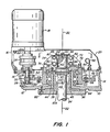
- FIG. l is a sectional view, in elevation, of mixer drive apparatus embodying the invention;
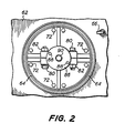
- FIG. 2 is a plan view, taken along the line 2-2 in FIG. l and showing the impeller shaft coupling structure from the top;
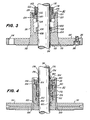
- FIG. 3 is an enlarged sectional view of the seal assembly of the mixer apparatus shown in FIG. l;
- FIG. 4 is a sectional view in elevation, similar to FIG. 3 showing a sealing assembly containing a double mechanical seal which may be used in lieu of the single mechanical seal assembly shown in FIG. 3.
- Referring more particularly to the drawings, there is shown a housing l0 having a base plate l2 and side walls l4. The housing l0 has an upper section l6 on which an electric motor l8 is mounted. The housing may be covered with a
guard 20. - The drive shaft of the apparatus is provided by the
shaft 22 of the motor which is connected through aflexible coupling 24 to adrive shaft extension 26.Bearings shaft extension 26. Theshaft extension 26 is the drive shaft portion on which apinion 30 is mounted. The drive shaft has an axis of rotation which is parallel to the axis of 32 of rotation of animpeller shaft 34. - The impeller shaft is coupled at the top thereof to the mixer drive and extends downwardly out of the mixer drive housing l0 into a tank or other vessel in which materials to be mixed are contained. This tank may be a closed tank, in which event the base plate l2 is connected to the nozzle assembly of the closed tank either directly or through adapter rings or flanges (not shown) so as to seal the nozzle. The closed tank is sealed by a
seal assembly 36 which includes aretaining hub 38 and asealing sleeve assembly 40 which will be described in detail hereinafter. The mixer apparatus may be used on an open tank, in which event the seal assembly need not be used. It will be apparent as the description proceeds that the seal assembly may readily be inserted in the field and without any modification of the mixer unit when required. - The impeller shaft torque and speed reduction is obtained through the use of a
ring gear 42 which is coupled to thepinion 30. The gears may provide a reduction of ten to eighteen to one in speed, and of course a corresponding increase in torque. Helical gears are shown for thering gear 42 and thepinion 30 and are preferred. If additional reduction and speed and increase in torque is required an extra pinion and spur gear may be used. - A
collar 44 extends upwardly and inwardly from the base plate l2 of the housing l0. The collar has ahole 46 therethrough, through which theimpeller shaft 34 extends out of the housing l0. The housing l0, itscollar 44 and other parts of the housing may be a casting which is suitable machined, especially along the inner periphery (which defines the hole 46) and outer periphery of thecollar 44. - The
collar 44 rotatably supports ahub 48 onbearings retainer 54 which is held down byscrews 56, only one of which is shown in FIG. l, but which are evenly spaced around thering 54. Thering gear 42 is attached to a flange on thehub 48 bybolts 58. An oil seal ring 60 is disposed between thehub 48 and the retainingring 54. The housing l0 is also closed by acover 62 which is sealed at thehub 48 by anouter oil seal 64. A chamber is defined under the cover within the housing l0 which contains a bath of lubricating oil. Adipstick 66 may be used to check the level of the oil. All of thegear drive bearings - The
impeller shaft 34 is cantilevered at its top end by acoupling 70 which is secured to the top end of thehub 48 bybolts 72. The top end of thehub 48 is rabbitted as shown at 74 so as to locate the coupling. The coupling has two sections 76 and 78 which define a split ring. The ring may have bearing surfaces on the inside thereof which engage the top end of the shaft. Four bolts, orcap screws 80 and their associatednuts 82 extend through the sections 76 and 78 and clamp theshaft 34 at its top end thereby supporting and cantilevering theshaft 34 only at its top end. No special guide bearings for the shaft are used or required. A key 84 connects the coupling to the shaft which has a key way for receiving the key 84. Portions of inner periphery of the split ring may be recessed so as to assure contact along four diametrically opposed surfaces of the top end of theshaft 34. - A
thrust plate 86 is attached byscrews 88 to the top of thecoupling 70. A bolt orcap screw 90 extends through a hole which is along theaxis 32 of the shaft into a threaded hole through the top surface of the top end of theshaft 34. The axial position of theshaft 34 may be adjusted by turning the screw. Preferably the shaft end is indexed and registered against the undersurface of the thrust plate when the shaft is located and secured to thecoupling 70. - The
hole 46 in thecollar 44 and theshaft 34 define an annular gap therebetween. This gap is substantially wider than required to accommodate the run-out of the shaft due to deflecting forces which may be applied thereto. Such forces are generated by fluid forces on the impeller as the impeller rotates in the medium being mixed. The gap is provided to receive theseal assembly 36. The retaininghub 38 of the assembly has aflange 94 which is connected to the housing base plate bybolts 98. The retaininghub 38 captures the sealingsleeve assembly 40 inside the gap and between the retaininghub 38 and thecoupling 70. - A collar l00 is attached to the impeller shaft as by a set screw l02 so as to normally dispose the under surface of the collar l00 above the surface of a radially inward extending step l04 of the retaining
hub 38. Preferably a sealing ring l06, which may be an "O" ring, is captured in a notch in the under surface of the collar l00 adjacent to the surface of theshaft 34. This sealing ring l06 is better shown in FIG. 3. The sealing ring fits into a chamfer l08 which extends around the inner edge of the step l04. When thesplit ring coupling 70 is loosened, theshaft 34 drops until the collar l00 engages the step l04. A static seal is then provided by the sealing ring l06. Then the closed tank with which the mixer apparatus is associated and on which the housing l0 is secured remains sealed. The coupling can then be removed to expose thesleeve assembly 40 for ready removal and replacement from the top of the apparatus. - The
flange 94 of the retaininghub 38 may be welded thereto as shown at ll0. The retaining hub may be made of stainless steel or any other suitable alloy or material in order to withstand corrosive environments, and a facing ll2 may be adhered to the underside of the retaininghub 38 and itsflange 94. - FIG. 3 shows additional threaded holes ll4 which may be used to attach the flange which assembles the mixer drive to the nozzle of a closed tank.
- FIG. l and FIG. 3 illustrate a single
mechanical sleeve assembly 40 as the seal. This assembly may be provided as a cartridge and secured in the retaininghub 38 by a retaining ring l20, which may be a "C" washer. Thesleeve assembly 40 has a sleeve ll6 which is attached to a ring l22 by a set screw ll8 in a ring l20 around the sleeve ll6. The sleeve ll6 is sealed by a seal ring (an "O" ring) l24. A plurality of springs l26 which bear against the ring l22 compress carbon washer l28 against a ceramic seat ring l30. Drive pins l27 extend from the ring l22 into the washer l28 so that the ring l22 and washer l28 and sleeve ll6 are coupled to rotate together. "O" ring seals l32 and l34 are located between the washer l28 and the sleeve ll6 and between the inner periphery of the retainingmember 38 and the seat l30. The seat l30 defines a seal face l40 with the washer l28. Pins l42 (see also FIG. l) extend into a slot l44 in the underside of thecoupling 70. These pins l42 engage thecoupling 70 in the slot l44 so that the sleeve assembly consisting of the inner sleeve ll6, the ring l22 and the washer stack l28 rotates with theshaft 34. - The seal face l40 is extremely close to the coupling member. The coupling member rigidly clamps and supports the
shaft 34. Accordingly there is very little deflection and run-out at the location of the seal face l40. Such run-out can be controlled to about 5 mils or less. Accordingly, thesleeve assembly 40 of the seal may be a low run-out dry running seal as shown in FIGS. l and 3. - When escape of any gas or other medium from the vessel is detrimental, a pressurized double mechanical seal, such as shown in FIG. 4 may be used as the
seal sleeve assembly 40. This assembly is also removable and replaceable by removing a retaining ring l50, similar to the ring l20 (FIG. 3). Thissleeve assembly 40 has two seat rings l52 and l54 at the bottom and top thereof. The upper seat ring l54 is assembled with a flanged ring l56 which is retained by the retaining ring l50. The rotating parts of theassembly 40 have two carbon washers l58 and l60 which, with the seats l52 and l54 define sealing faces l62 and l64. The washers l58 and l60 are biased against the faces by collars l68 and l70 which are engaged by a helical spring l72. These rotating parts of thesleeve assembly 40 rotate with a sleeve l74 which is indexed against the top surface of the collar l00. Tangs l76 extend upwardly into the slot l44 (FIG. l) and engage thecoupling 70 so that the sleeve l74 and the rest of the rotating parts of theassembly 40 are driven and rotate with the shaft 37. A ring l80 which is disposed in a slot in the sleeve l74 retains the sealingassembly 40 on the sleeve l74 between the ring l80 and a step l82 so that the sleeve l74 and all of the other parts of the sealingassembly 40 may be removed as a unit for replacement when the seal faces l62 and l64 wear out. Holes l84 for pulling tools may be provided in the flanged ring l56 to assist in the removal of the sealingassembly 40. - The sealing faces are kept under pressure of a hydraulic liquid, such as a conventional seal lubricant, which is supplied through lubricant inlet and outlet passages l86 and l88. The cavity into which the pressurized lubricant is supplied is defined by the inside surface of the retaining
hub 38, the sleeve l74 and the upper and lower seats l52 and l54, l56. Seal rings, such as "O" rings are provided between the sleeve l74 and the shaft 37 and between the seats l54 and l56 and theseat 52 and the retaining hub so as to preclude any leakage through theseal assembly 36. - The rotary parts of the sealing
sleeve assembly 40 of the doublemechanical seal assembly 36 shown in FIG. 4, similarly with therotary seal assembly 40 of the single mechanical seal assembly shown in FIG. 3 are located adjacent to the rigidly supported top end of theshaft 34 where deflection is minimal and run out at the seal faces l62 and l64 is not excessive (for example, approximately 5 mils). Accordingly the sealingsleeve assembly 40 provides reliable sealing performance over a long lifetime. - Since the cavity containing the rotating seal parts of the double mechanical seal assembly shown in FIG. 4 are pressurized to a pressure greater than the tank with which the mixer drive is used, the pressure in the tank is not capable of driving material or gases contained therein through the
seal assembly 36 into the environment. - It will be apparent that removal of the
coupling 70 will enable the replacement of therotary sealing sleeve 40 parts from the top of the unit as was the case with the single mechanical seal shown in FIGS. l and 3. - From the foregoing description it will be apparent that there has been provided improved mixer drive apparatus. Variations and modifications of the herein described apparatus, within the scope of the invention, will undoubtedly suggest themselves to those skilled in the art. Accordingly, the foregoing description should be taken as illustrative and not in a limiting sense.
Claims (10)
Priority Applications (1)
| Application Number | Priority Date | Filing Date | Title |
|---|---|---|---|
| AT87104631T ATE72412T1 (en) | 1986-03-31 | 1987-03-27 | DRIVE FOR A MIXER. |
Applications Claiming Priority (2)
| Application Number | Priority Date | Filing Date | Title |
|---|---|---|---|
| US06/846,317 US4721003A (en) | 1986-03-31 | 1986-03-31 | Mixer drive apparatus |
| US846317 | 1992-03-05 |
Publications (3)
| Publication Number | Publication Date |
|---|---|
| EP0239962A2 true EP0239962A2 (en) | 1987-10-07 |
| EP0239962A3 EP0239962A3 (en) | 1989-12-13 |
| EP0239962B1 EP0239962B1 (en) | 1992-02-05 |
Family
ID=25297539
Family Applications (1)
| Application Number | Title | Priority Date | Filing Date |
|---|---|---|---|
| EP87104631A Expired - Lifetime EP0239962B1 (en) | 1986-03-31 | 1987-03-27 | Mixer drive apparatus |
Country Status (11)
| Country | Link |
|---|---|
| US (1) | US4721003A (en) |
| EP (1) | EP0239962B1 (en) |
| JP (1) | JPS62241533A (en) |
| KR (1) | KR870008610A (en) |
| AT (1) | ATE72412T1 (en) |
| AU (1) | AU585801B2 (en) |
| CA (1) | CA1270245A (en) |
| DE (1) | DE3776584D1 (en) |
| IL (1) | IL81931A0 (en) |
| MY (1) | MY101067A (en) |
| ZA (1) | ZA871942B (en) |
Cited By (6)
| Publication number | Priority date | Publication date | Assignee | Title |
|---|---|---|---|---|
| WO2005104706A2 (en) | 2004-04-27 | 2005-11-10 | Baxter International Inc. | Stirred-tank reactor system |
| EP1871513A2 (en) * | 2005-04-22 | 2008-01-02 | Hyclone Laboratories, Inc. | Mixing systems and related mixers |
| CN101163538B (en) * | 2005-04-22 | 2012-04-18 | 海克隆实验室有限公司 | Mixing systems and related mixers |
| US8608369B2 (en) | 2011-01-07 | 2013-12-17 | Hyclone Laboratories, Inc. | Methods and systems for heating and mixing fluids |
| US9314751B2 (en) | 2011-01-07 | 2016-04-19 | Life Technologies Corporation | Methods and apparatus for mixing and shipping fluids |
| US9687799B2 (en) | 2014-03-17 | 2017-06-27 | Advanced Scientifics, Inc. | Transportable mixing system for biological and pharmaceutical materials |
Families Citing this family (7)
| Publication number | Priority date | Publication date | Assignee | Title |
|---|---|---|---|---|
| US4884245A (en) * | 1989-03-21 | 1989-11-28 | Jwi, Incorporated | Quick-connection drive coupling for mixing tank |
| US5368390A (en) * | 1993-03-01 | 1994-11-29 | General Signal Corporation | Mixer systems |
| US5560709A (en) * | 1995-11-13 | 1996-10-01 | General Signal Corporation | Mixer drive apparatus enabling radial changing of shaft seal |
| US5960671A (en) * | 1997-09-30 | 1999-10-05 | Philadelphia Gear Corp. | Eccentric pivotable mounting for changing gear reduction ratios |
| US6058793A (en) * | 1999-01-19 | 2000-05-09 | Chemineer, Inc. | Parallel shaft speed reducer with sump and dry well |
| US20130068057A1 (en) * | 2011-09-16 | 2013-03-21 | Hamilon Sundstrand Corporation | Idler gear assembly for a generator |
| US20140251881A1 (en) * | 2013-03-11 | 2014-09-11 | Heartland Technology Partners Llc | Concentrated wastewater slurry thickening and storage system and stabilization batch treatment plant |
Citations (8)
| Publication number | Priority date | Publication date | Assignee | Title |
|---|---|---|---|---|
| DE519633C (en) * | 1927-07-30 | 1931-03-02 | Walther Feld & Co G M B H | Washer or mixer with hanging centrifugal shaft |
| DE520937C (en) * | 1930-02-08 | 1931-03-14 | Walther Feld & Co G M B H | Washer or mixer with hanging centrifugal shaft |
| US3202007A (en) * | 1962-03-15 | 1965-08-24 | King Of Prussia Res And Dev Co | Top-entering mixer drive |
| US3286994A (en) * | 1965-02-03 | 1966-11-22 | Gen American Transportaion Cor | Agitating apparatus |
| DE1285459B (en) * | 1961-12-06 | 1968-12-19 | Lohmann & Stolterfoht Ag | Agitator gear |
| GB1172653A (en) * | 1968-02-13 | 1969-12-03 | Gerhard Kestermann Zahnraeder | Improvements in or relating to Driving Means for Agitators. |
| US3575531A (en) * | 1968-12-11 | 1971-04-20 | Bird Machine Co | Motor and gear system |
| US4152082A (en) * | 1977-04-29 | 1979-05-01 | Machinefabriek W. Hubert & Co. B.V. | Device for driving an agitator, more particularly an aerator for waste water |
Family Cites Families (12)
| Publication number | Priority date | Publication date | Assignee | Title |
|---|---|---|---|---|
| US1656935A (en) * | 1926-10-05 | 1928-01-24 | William H Bahan | Hub |
| US1903060A (en) * | 1931-06-18 | 1933-03-28 | Mitchell Orville | Shaft mounting for rotatable cylinders |
| US2257747A (en) * | 1940-09-05 | 1941-10-07 | Jr Warren G Jones | Gear speed reducer and the like |
| US2441446A (en) * | 1944-12-23 | 1948-05-11 | Falk Corp | Fan drive |
| US2670697A (en) * | 1945-08-22 | 1954-03-02 | Edgar N Meakin | Pellet mill |
| US2505575A (en) * | 1948-03-03 | 1950-04-25 | Ray Bert | Power gear |
| US2639624A (en) * | 1949-08-19 | 1953-05-26 | Falk Corp | Yieldable power transmission |
| US2612788A (en) * | 1951-01-22 | 1952-10-07 | American Pulley Co | Combined shaft journal and drive unit |
| US2881880A (en) * | 1956-09-19 | 1959-04-14 | Niagara Machine & Tool Works | Power press drive mechanism |
| US3373626A (en) * | 1966-09-22 | 1968-03-19 | Falk Corp | Mounting assembly for shaft mounted gear drive unit |
| DE2119325C3 (en) * | 1971-04-21 | 1973-10-04 | Wgw Westdeutsche Getriebe- Und Kupplungswerke Gmbh, 4630 Bochum | Positive coupling for the transmission of large torques |
| JPS58118376A (en) * | 1982-01-07 | 1983-07-14 | Nippon Pillar Packing Co Ltd | Mechanical seal |
-
1986
- 1986-03-31 US US06/846,317 patent/US4721003A/en not_active Expired - Lifetime
-
1987
- 1987-03-03 CA CA000531015A patent/CA1270245A/en not_active Expired - Lifetime
- 1987-03-17 ZA ZA871942A patent/ZA871942B/en unknown
- 1987-03-18 IL IL81931A patent/IL81931A0/en unknown
- 1987-03-20 AU AU70464/87A patent/AU585801B2/en not_active Ceased
- 1987-03-27 DE DE8787104631T patent/DE3776584D1/en not_active Expired - Lifetime
- 1987-03-27 AT AT87104631T patent/ATE72412T1/en not_active IP Right Cessation
- 1987-03-27 EP EP87104631A patent/EP0239962B1/en not_active Expired - Lifetime
- 1987-03-30 KR KR870002949A patent/KR870008610A/en not_active Application Discontinuation
- 1987-03-30 MY MYPI87000393A patent/MY101067A/en unknown
- 1987-03-31 JP JP62079549A patent/JPS62241533A/en active Pending
Patent Citations (8)
| Publication number | Priority date | Publication date | Assignee | Title |
|---|---|---|---|---|
| DE519633C (en) * | 1927-07-30 | 1931-03-02 | Walther Feld & Co G M B H | Washer or mixer with hanging centrifugal shaft |
| DE520937C (en) * | 1930-02-08 | 1931-03-14 | Walther Feld & Co G M B H | Washer or mixer with hanging centrifugal shaft |
| DE1285459B (en) * | 1961-12-06 | 1968-12-19 | Lohmann & Stolterfoht Ag | Agitator gear |
| US3202007A (en) * | 1962-03-15 | 1965-08-24 | King Of Prussia Res And Dev Co | Top-entering mixer drive |
| US3286994A (en) * | 1965-02-03 | 1966-11-22 | Gen American Transportaion Cor | Agitating apparatus |
| GB1172653A (en) * | 1968-02-13 | 1969-12-03 | Gerhard Kestermann Zahnraeder | Improvements in or relating to Driving Means for Agitators. |
| US3575531A (en) * | 1968-12-11 | 1971-04-20 | Bird Machine Co | Motor and gear system |
| US4152082A (en) * | 1977-04-29 | 1979-05-01 | Machinefabriek W. Hubert & Co. B.V. | Device for driving an agitator, more particularly an aerator for waste water |
Cited By (21)
| Publication number | Priority date | Publication date | Assignee | Title |
|---|---|---|---|---|
| US9540606B2 (en) | 2004-04-27 | 2017-01-10 | Life Technologies Corporation | Stirred tank reactor systems and methods of use |
| EP1756259A2 (en) * | 2004-04-27 | 2007-02-28 | Baxter International Inc. | Stirred-tank reactor system |
| EP1756259A4 (en) * | 2004-04-27 | 2009-09-23 | Baxter Int | Stirred-tank reactor system |
| US11591556B2 (en) | 2004-04-27 | 2023-02-28 | Life Technologies Corporation | Stirred tank reactor systems and methods of use |
| US8623640B2 (en) | 2004-04-27 | 2014-01-07 | Hyclone Laboratories, Inc. | Stirred tank reactor systems and methods of use |
| US10640741B2 (en) | 2004-04-27 | 2020-05-05 | Life Technologies Corporation | Stirred tank reactor systems and methods of use |
| WO2005104706A2 (en) | 2004-04-27 | 2005-11-10 | Baxter International Inc. | Stirred-tank reactor system |
| EP1871513A2 (en) * | 2005-04-22 | 2008-01-02 | Hyclone Laboratories, Inc. | Mixing systems and related mixers |
| US7682067B2 (en) | 2005-04-22 | 2010-03-23 | Hyclone Laboratories, Inc. | Mixing systems and related mixers |
| CN101163538B (en) * | 2005-04-22 | 2012-04-18 | 海克隆实验室有限公司 | Mixing systems and related mixers |
| EP1871513A4 (en) * | 2005-04-22 | 2012-11-07 | Hyclone Lab Inc | Mixing systems and related mixers |
| US9289735B2 (en) | 2011-01-07 | 2016-03-22 | Life Technologies Corporation | Systems for inactivating fluid cultures through heating |
| US9314751B2 (en) | 2011-01-07 | 2016-04-19 | Life Technologies Corporation | Methods and apparatus for mixing and shipping fluids |
| US10308907B2 (en) | 2011-01-07 | 2019-06-04 | Life Technologies Corporation | Systems for inactivating fluid cultures through heating |
| US10525425B2 (en) | 2011-01-07 | 2020-01-07 | Life Technologies Corporation | Methods and apparatus for processing fluids |
| US8961875B2 (en) | 2011-01-07 | 2015-02-24 | Life Technologies Corporation | Methods for inactivating fluid cultures through heating |
| US8608369B2 (en) | 2011-01-07 | 2013-12-17 | Hyclone Laboratories, Inc. | Methods and systems for heating and mixing fluids |
| US11786874B2 (en) | 2011-01-07 | 2023-10-17 | Life Technologies Corporation | Methods and apparatus for processing fluids |
| US9687799B2 (en) | 2014-03-17 | 2017-06-27 | Advanced Scientifics, Inc. | Transportable mixing system for biological and pharmaceutical materials |
| US10399049B2 (en) | 2014-03-17 | 2019-09-03 | Advanced Scientifics, Inc. | Transportable mixing system for biological and pharmaceutical materials |
| US11179687B2 (en) | 2014-03-17 | 2021-11-23 | Advanced Scientifics, Inc. | Transportable mixing system for biological and pharmaceutical materials |
Also Published As
| Publication number | Publication date |
|---|---|
| KR870008610A (en) | 1987-10-19 |
| DE3776584D1 (en) | 1992-03-19 |
| ZA871942B (en) | 1987-09-07 |
| JPS62241533A (en) | 1987-10-22 |
| ATE72412T1 (en) | 1992-02-15 |
| AU7046487A (en) | 1987-10-08 |
| EP0239962A3 (en) | 1989-12-13 |
| AU585801B2 (en) | 1989-06-22 |
| IL81931A0 (en) | 1987-10-20 |
| US4721003A (en) | 1988-01-26 |
| CA1270245A (en) | 1990-06-12 |
| MY101067A (en) | 1991-07-16 |
| EP0239962B1 (en) | 1992-02-05 |
Similar Documents
| Publication | Publication Date | Title |
|---|---|---|
| EP0239962B1 (en) | Mixer drive apparatus | |
| US5553867A (en) | Triple cartridge seal having one inboard and two concentric seals for chemical processing pump | |
| EP0344532B1 (en) | Sealing device of the bearing of a rotating shaft with its drive unit | |
| US4990068A (en) | Unique grease lubricated ball bearing canned motor pump | |
| JP5143737B2 (en) | Magnetic seal assembly | |
| US2958292A (en) | Canned motor | |
| JP2005523814A (en) | Stirrer drive device | |
| US5040899A (en) | Mixer | |
| CN105597652B (en) | Non-contact sealed reaction kettle | |
| US5649765A (en) | Conical mixer apparatus with contamination-preventing orbit arm assembly | |
| SE514127C2 (en) | Device for preventing fluid leakage from a vessel, shaft assembly and method of servicing shaft components | |
| JP4920782B2 (en) | Lubricating oil circulation system for centrifuge | |
| US6217219B1 (en) | Bearing seal with uniform fluid purge | |
| US5720486A (en) | Self-formed labyrinth seal | |
| EP0477153B1 (en) | Seal device | |
| US6533540B1 (en) | Double-seal/oil-reservoir system for a motor/pump assembly | |
| JP4920657B2 (en) | Rotating shaft support device for centrifuge | |
| CN215334458U (en) | Rotator of ultrahigh pressure mechanical sealing structure | |
| CN212563761U (en) | Bearing box oil-resistant device | |
| KR100320123B1 (en) | Supporting structure of the axis of revolution | |
| US6309199B1 (en) | Assemblies for modular fluid pump | |
| CN218572329U (en) | Dental handpiece aircraft nose and dental handpiece | |
| JPS6110112A (en) | Submerged bearing | |
| JP2005524033A (en) | Hydraulic drive motor used in high pressure environment | |
| AU2020427546A1 (en) | Two-piece oil filter assembly for pumps |
Legal Events
| Date | Code | Title | Description |
|---|---|---|---|
| PUAI | Public reference made under article 153(3) epc to a published international application that has entered the european phase |
Free format text: ORIGINAL CODE: 0009012 |
|
| AK | Designated contracting states |
Kind code of ref document: A2 Designated state(s): AT BE CH DE FR GB IT LI LU NL SE |
|
| PUAL | Search report despatched |
Free format text: ORIGINAL CODE: 0009013 |
|
| AK | Designated contracting states |
Kind code of ref document: A3 Designated state(s): AT BE CH DE FR GB IT LI LU NL SE |
|
| 17P | Request for examination filed |
Effective date: 19900412 |
|
| 17Q | First examination report despatched |
Effective date: 19901023 |
|
| GRAA | (expected) grant |
Free format text: ORIGINAL CODE: 0009210 |
|
| ITF | It: translation for a ep patent filed |
Owner name: BARZANO' E ZANARDO ROMA S.P.A. |
|
| AK | Designated contracting states |
Kind code of ref document: B1 Designated state(s): AT BE CH DE FR GB IT LI LU NL SE |
|
| REF | Corresponds to: |
Ref document number: 72412 Country of ref document: AT Date of ref document: 19920215 Kind code of ref document: T |
|
| REF | Corresponds to: |
Ref document number: 3776584 Country of ref document: DE Date of ref document: 19920319 |
|
| PG25 | Lapsed in a contracting state [announced via postgrant information from national office to epo] |
Ref country code: LU Free format text: LAPSE BECAUSE OF NON-PAYMENT OF DUE FEES Effective date: 19920331 |
|
| ET | Fr: translation filed | ||
| PLBE | No opposition filed within time limit |
Free format text: ORIGINAL CODE: 0009261 |
|
| STAA | Information on the status of an ep patent application or granted ep patent |
Free format text: STATUS: NO OPPOSITION FILED WITHIN TIME LIMIT |
|
| 26N | No opposition filed | ||
| PGFP | Annual fee paid to national office [announced via postgrant information from national office to epo] |
Ref country code: FR Payment date: 19930219 Year of fee payment: 7 |
|
| PGFP | Annual fee paid to national office [announced via postgrant information from national office to epo] |
Ref country code: SE Payment date: 19930222 Year of fee payment: 7 |
|
| PGFP | Annual fee paid to national office [announced via postgrant information from national office to epo] |
Ref country code: CH Payment date: 19930301 Year of fee payment: 7 |
|
| PGFP | Annual fee paid to national office [announced via postgrant information from national office to epo] |
Ref country code: AT Payment date: 19930304 Year of fee payment: 7 |
|
| PGFP | Annual fee paid to national office [announced via postgrant information from national office to epo] |
Ref country code: BE Payment date: 19930316 Year of fee payment: 7 |
|
| PGFP | Annual fee paid to national office [announced via postgrant information from national office to epo] |
Ref country code: NL Payment date: 19930331 Year of fee payment: 7 |
|
| PG25 | Lapsed in a contracting state [announced via postgrant information from national office to epo] |
Ref country code: AT Effective date: 19940327 |
|
| PG25 | Lapsed in a contracting state [announced via postgrant information from national office to epo] |
Ref country code: SE Free format text: LAPSE BECAUSE OF NON-PAYMENT OF DUE FEES Effective date: 19940328 |
|
| PG25 | Lapsed in a contracting state [announced via postgrant information from national office to epo] |
Ref country code: LI Effective date: 19940331 Ref country code: CH Effective date: 19940331 Ref country code: BE Effective date: 19940331 |
|
| BERE | Be: lapsed |
Owner name: GENERAL SIGNAL CORP. Effective date: 19940331 |
|
| PG25 | Lapsed in a contracting state [announced via postgrant information from national office to epo] |
Ref country code: NL Effective date: 19941001 |
|
| NLV4 | Nl: lapsed or anulled due to non-payment of the annual fee | ||
| PG25 | Lapsed in a contracting state [announced via postgrant information from national office to epo] |
Ref country code: FR Effective date: 19941130 |
|
| REG | Reference to a national code |
Ref country code: CH Ref legal event code: PL |
|
| REG | Reference to a national code |
Ref country code: FR Ref legal event code: ST |
|
| EUG | Se: european patent has lapsed |
Ref document number: 87104631.4 Effective date: 19941010 |
|
| PGFP | Annual fee paid to national office [announced via postgrant information from national office to epo] |
Ref country code: DE Payment date: 19960224 Year of fee payment: 10 |
|
| PG25 | Lapsed in a contracting state [announced via postgrant information from national office to epo] |
Ref country code: DE Effective date: 19971202 |
|
| REG | Reference to a national code |
Ref country code: GB Ref legal event code: IF02 |
|
| PGFP | Annual fee paid to national office [announced via postgrant information from national office to epo] |
Ref country code: GB Payment date: 20020403 Year of fee payment: 16 |
|
| PG25 | Lapsed in a contracting state [announced via postgrant information from national office to epo] |
Ref country code: GB Free format text: LAPSE BECAUSE OF NON-PAYMENT OF DUE FEES Effective date: 20030327 |
|
| GBPC | Gb: european patent ceased through non-payment of renewal fee |
Effective date: 20030327 |
|
| PG25 | Lapsed in a contracting state [announced via postgrant information from national office to epo] |
Ref country code: IT Free format text: LAPSE BECAUSE OF NON-PAYMENT OF DUE FEES;WARNING: LAPSES OF ITALIAN PATENTS WITH EFFECTIVE DATE BEFORE 2007 MAY HAVE OCCURRED AT ANY TIME BEFORE 2007. THE CORRECT EFFECTIVE DATE MAY BE DIFFERENT FROM THE ONE RECORDED. Effective date: 20050327 |