EP0237601A1 - Method for the photogrammetrical measurement of an object with at least one solid-state image sensor - Google Patents
Method for the photogrammetrical measurement of an object with at least one solid-state image sensor Download PDFInfo
- Publication number
- EP0237601A1 EP0237601A1 EP86103748A EP86103748A EP0237601A1 EP 0237601 A1 EP0237601 A1 EP 0237601A1 EP 86103748 A EP86103748 A EP 86103748A EP 86103748 A EP86103748 A EP 86103748A EP 0237601 A1 EP0237601 A1 EP 0237601A1
- Authority
- EP
- European Patent Office
- Prior art keywords
- image
- réseau
- sensor
- area
- recording
- Prior art date
- Legal status (The legal status is an assumption and is not a legal conclusion. Google has not performed a legal analysis and makes no representation as to the accuracy of the status listed.)
- Granted
Links
Images


Classifications
-
- G—PHYSICS
- G01—MEASURING; TESTING
- G01C—MEASURING DISTANCES, LEVELS OR BEARINGS; SURVEYING; NAVIGATION; GYROSCOPIC INSTRUMENTS; PHOTOGRAMMETRY OR VIDEOGRAMMETRY
- G01C11/00—Photogrammetry or videogrammetry, e.g. stereogrammetry; Photographic surveying
- G01C11/04—Interpretation of pictures
Definitions
- the invention relates to a method for the photogrammetric detection of an object with the aid of at least one opto-electrical solid-state surface sensor, the image area of which is smaller than that of the desired overall image, the point field of a delicious covering the overall image (glass plate with suitable, grid-like distributed) in the photogrammetric imaging system Dot marks) are included and the area sensor is arranged in the imaging space so that it maps at least one mesh of the réelle across the entire area of the sensor image, and for the opto-electrical analog-digital conversion of images present analogously, the transparent template is brought into contact with a scanning reseau and together is projected onto a sensor surface with the scanning reseau with the aid of a lens, and the sensor surface and lens are moved together for the continuous recording of Jewish mesh to Jewish mesh.
- the invention further relates to a method for the photogrammetric detection of an object with the aid of at least one opto-electrical solid-state surface sensor, the image area of which is smaller than that of the desired overall image, wherein in the photogrammetric imaging system, the point field of a delicious covering the overall image (glass plate with suitable, grid-like dot markings) is included and the area sensor is arranged in the imaging space in such a way that it maps at least one mesh of the Nursing across the sensor image, and for an opto-electrical recording system Recording static objects of a sensor surface is arranged behind the chamber clergy arranged in the image plane of the receiving chamber, so that the chamber éseau can be projected onto the sensor surface together with the recording object with the aid of the imaging system of the recording chamber, the sensor surface being shifted from Victoria ash to Jewish ash for continuous recording.
- the transparent template to be digitized lies under the Victoria plate on a translucent surface (e.g. opal glass plate) and is imaged with transmitted light on the sensor surface.
- the sensor surface and imaging object are guided for continuous exposure from Victoria ash to Victoria ash.
- the sampling rate can be changed, i.e. the size of the picture element in the template can be specified, which is imaged on a sensor element of the sensor block.
- the clergy must be adjusted in terms of mesh size and dot marking thickness (exchange of the réelle plate).
- the aforementioned pre-publication also shows the arrangement of a sensor block behind the image plane of a photogrammetric recording system.
- the Bennett points are mapped onto the sensor surface together with the object to be photographed using the lens of the receiving chamber.
- a single sensor for continuous exposure can be guided from résea ash to Kir ash in the manner of a flat bed scanner to detect the total format.
- a simultaneous recording of the overall format is possible if several sensor blocks are arranged in a grid in several associations behind a common Guatemala plate.
- the grid spacing of the sensor blocks in the associations is determined on the one hand by the grid spacing of the Victoria points and becomes different must consider that the light-sensitive surfaces of the sensor blocks can only be arranged side by side up to a certain minimum distance.
- the invention has for its object to provide various methods for the photogrametric detection of an object.
- the stated object is achieved in that the clergy points depicted in the digital partial image of the area sensor are adapted to their desired positions in the scanning reseau and that the transformation parameters obtained in this way are used to transfer the partial image into a uniform overall image system.
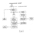
- This method for digitally converting analog image templates is illustrated in more detail in FIG. 1 using a block diagram.
- the transformation parameters can be stored together with the digital partial image, or can be used to combine the partial images into an overall digital image by equalization.
- the system can basically work according to the principle shown in FIG. 1.
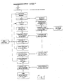
- the automatic point recognition carried out by digital processing of the partial images is supported by additionally provided approximate image coordinates in the partial image system, which are entered into an auxiliary system and transfor into the coordinate system of the scanning level be miert in order to control the area sensor via Réseaa meshes, which contain the pixels to be determined, and which are finally transformed into the system of the partial image detected by the area sensor. This process is illustrated in FIG. 4.
- FIG. 4 A method according to FIG. 4 can also be carried out simultaneously for several analog image templates.
- FIG. 5 shows the use of three analog image templates in connection with three scanning levels.
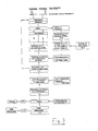
- This digital stereo image measurement with control of the object point is shown in FIG. 3.
- This measuring principle corresponds in principle to the analytical plotter; it allows dynamic spatial measurement in the stereoscopically realized model and provides on-line mapping (stereo mapping) or spatial object coordinates.
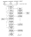
- FIG. 6 This digital mono mild imaging and image measurement system is illustrated in FIG. 6.
- the system corresponds to that of FIG. 2, but the area sensor is guided behind a réelle plate mounted in the imaging plane of the receiving chamber.
- the object image created in the recording chamber is imaged a second time together with the chamber reseau, the area sensor being provided in this second imaging area, so as to vary the imaging scale of the digital image. Similar to the system shown in FIG. 1, the size of the sensor elements of differently sized image elements in the image system can thus be assigned to the receiving chamber.
- the system corresponds in principle to that of FIG. 3, but the area sensor is guided behind a clar plate mounted in the imaging plane of the receiving chamber. Since the system of the chamber reseau also represents the image space system, the image coordinates obtained from object points can be used directly to control the scanning and measuring system; in contrast to the method according to FIG. 3, a transition from the chamber system to the system of a scanner is not necessary.
- the sensors are positioned optically, the varieties must be designed so that they can be measured with the greatest possible accuracy.
- black, right-angled crosses can be determined with an accuracy of 1 to 3 ⁇ m. This accuracy can only be reliably achieved if the citratives with the same darkness.
- the Karl point and the object have the same darkness, the point cannot be identified and the sensor cannot be positioned.
- the separation of clergy and image information can be carried out numerically if the signal intensity of the clergy point differs significantly from that of the background, i.e. if the difference in gray values is greater than the noise component in the image. The higher the noise component in the image and the more inhomogeneous the background, the worse the accuracy of the point determination.
- an optical separation of the object and the clergy by double exposure is proposed according to the invention, the securities points being mapped by the area sensor in the case of external, separate illumination, without the object information being visible, so that the first sensor image obtained in this way is stored digitally, and that the object having the same geometric relationship to the clergy is then imaged and the second sensor image obtained in this way is also stored digitally.
- the point determination for sensor positioning and then the geometric evaluation of the object image are carried out in the first image, which only has the Victoria points, and if, when evaluating the second sensor image, the measured image coordinates are specified directly in the coordination system of the clergy by the transformation parameters found .
- the geometric relationship between the images of the Irish and the object is only known if the sensor has not changed in the time between the images.
- the cycle time must therefore be as short as possible.
- Commercial CCD video cameras and analog-digital converters work at a frequency of 1/30 sec. This cycle time can be achieved when using two image memories and suitable lighting control.
- FIG. 9 illustrates the data flow for the recording of a partial image as a function of the processing time.
- the time t3 is irrelevant to the geometric stability of the system, since the digitally stored images are unchangeable over any period of time.
- the optoelectrical solid-state area sensor cannot be brought close enough to the chamber reseau, problems arise in sharply sliding the object or image and réelle at the same time. If the level of the Georgia does not coincide with the imaging level, the clergy is blurred on the sensor surface due to the flat exit pupil (AP) of the taking lens. It is therefore advantageous according to the invention if, in such cases, the imaging plane of the receptacle in which the surface sensor is guided is arranged outside the plane of the foster, and that the concerned is mapped onto the sensor surface with a second central projection.
- the chamber reséau is projected into the recording plane with the sharpest contours with the further advantage that the Kir marks are simulated in time can be read in tan or alternately. If the distance between the clergy and the image plane and the surface of the AP are sufficiently large, the contours of the clergy designed by the photographing lens appear very blurred and therefore almost transparent. This also enables the detection of object points normally hidden by the clergy. This example above is explained theoretically in FIG. 10.
Landscapes
- Engineering & Computer Science (AREA)
- Multimedia (AREA)
- Physics & Mathematics (AREA)
- General Physics & Mathematics (AREA)
- Radar, Positioning & Navigation (AREA)
- Remote Sensing (AREA)
- Length Measuring Devices By Optical Means (AREA)
- Solid State Image Pick-Up Elements (AREA)
- Photometry And Measurement Of Optical Pulse Characteristics (AREA)
- Transforming Light Signals Into Electric Signals (AREA)
Abstract
Description
Die Erfindung betrifft ein Verfahren zur photogrammetrischen Erfassung eines Objektes mit Hilfe zumindest eines opto-elektrischen Festkörper-Flächensensors, dessen Bildfläche kleiner ist als die des angestrebten Gesamtbildes, wobei in das photogrammetrische Abbildungssystem das Punktfeld eines das Gesamtbild abdeckenden Réseaus (Glasplatte mit geeigneten, rasterartig verteilten Punktmarkierungen) einbezogen und der Flächensensor so im Abbildungsraum angeordnet werden, daß er jeweils zumindest eine Masche des Réseaus flächendeckend im Sensorbild abbildet, und wobei zur opto-elektrischen Analog-Digital-Wandlung analog vorliegender Bilder die transparente Vorlage mit einem Abtastréseau in Kontakt gebracht und gemeinsam mit dem Abtastréseau mit Hilfe eines Objektivs auf eine Sensorfläche projiziert wird, und wobei Sensorfläche und Objektiv zur fortlaufenden Aufnahme von Réseaumasche zu Réseaumasche gemeinsam verschoben werden.The invention relates to a method for the photogrammetric detection of an object with the aid of at least one opto-electrical solid-state surface sensor, the image area of which is smaller than that of the desired overall image, the point field of a réseau covering the overall image (glass plate with suitable, grid-like distributed) in the photogrammetric imaging system Dot marks) are included and the area sensor is arranged in the imaging space so that it maps at least one mesh of the réseau across the entire area of the sensor image, and for the opto-electrical analog-digital conversion of images present analogously, the transparent template is brought into contact with a scanning reseau and together is projected onto a sensor surface with the scanning reseau with the aid of a lens, and the sensor surface and lens are moved together for the continuous recording of réseau mesh to réseau mesh.
Die Erfindung betrifft ferner ein Verfahren zur photogrammetrischen Erfassung eines Objektes mit Hilfe zumindest eines opto-elektrischen Festkörper-Flächensensors, dessen Bildfläche kleiner ist als die des angestrebten Gesamtbildes, wobei in das photogrammetrische Abbildungssystem das Punktfeld eines das Gesamtbild abdeckenden Réseaus (Glasplatte mit geeigneten, rasterartig verteilten Punktmarkierungen) einbezogen und der Flächensensor so im Abbildungsraum angeordnet werden, daß er jeweils zumindest eine Masche des Réseaus flächendeckend im Sensorbild abbildet, und wobei für ein opto-elektrisches Aufnahmesystem zur Aufnahme statischer Objekte eines Sensorfläche hinter dem in der Bildebene der Aufnahmekammer angeordneten Kammerréseau angeordnet wird, so daß das Kammeréseau gemeinsam mit dem Aufnahmeobjekt mit Hilfe des Abbildungssystems der Aufnahmekammer auf die Sensorfläche projizierbar ist, wobei die Sensorfläche zur fortlaufenden Aufnahme von Réseaumasche zu Réseaumasche verschoben wird.The invention further relates to a method for the photogrammetric detection of an object with the aid of at least one opto-electrical solid-state surface sensor, the image area of which is smaller than that of the desired overall image, wherein in the photogrammetric imaging system, the point field of a réseau covering the overall image (glass plate with suitable, grid-like dot markings) is included and the area sensor is arranged in the imaging space in such a way that it maps at least one mesh of the réseau across the sensor image, and for an opto-electrical recording system Recording static objects of a sensor surface is arranged behind the chamber réseau arranged in the image plane of the receiving chamber, so that the chamber éseau can be projected onto the sensor surface together with the recording object with the aid of the imaging system of the recording chamber, the sensor surface being shifted from réseau ash to réseau ash for continuous recording.
Diese Verfahren lassen sich der DE-C2- 34 28 325 entnehmen. Wird bei diesem Verfahren eine das gesamte zu erfassende Bildformat abdeckende Réseauplatte in den Abbildungsprozeß einbezogen, so können die auf den Flächen der Sensorblöcke entstandenen Teilbilder im Rahmen der digitalen Bildauswertung numerisch mit Hilfe der auf den Sensorflächen mit abgebildeten Réseaupunkte eindeutig in die Ebene des Réseaus transformiert werden. An die physikalische Lage der Sensorblöcke im Abbildungsraum sind dann nur geringe, instrumentell mit wenig Aufwand zu verwirklichende Anforderungen zu stellen: Es soll mindestens je eine Masche des Réseaus flächendeckend auf die Sensorflächen mit abgebildet werden; und die Sensorflächen sollen so nahe an die Réseauebene herangeführt sein, daß die Punkte des Réseaus zusammen mit dem Aufnahmeobjekt ausreichend scharf abgebildet werden. Durch die Transformation der auf den Bildflächen der einzelnen Sensorblöcke entstandenen Teilbilder in die Ebene des Réseaus wird das gesamte Bildformat mit hoher, durch die kalibrierte Réseauplatte vorgegebenen Genauigkeit erhalten.These processes can be found in DE-C2- 34 28 325. If a réseau plate covering the entire image format to be recorded is included in the imaging process in this process, the partial images created on the surfaces of the sensor blocks can be numerically transformed into the level of the réseau as part of the digital image evaluation using the réseau points imaged on the sensor surfaces . The physical position of the sensor blocks in the imaging area is then subject to only minor requirements that can be implemented with little effort: at least one mesh of the réseau should be mapped across the sensor surfaces; and the sensor surfaces should be brought so close to the réseau plane that the points of the réseau together with the object to be photographed are sufficiently sharp. By transforming the partial images created on the image areas of the individual sensor blocks into the level of the réseau, the entire image format is obtained with a high degree of accuracy, which is predetermined by the calibrated réseau plate.
Ein Réseau im Abbildungsvorgang erlaubt einerseits die Konstruktion eines Flachbett-Abtasters hoher Genauigkeit mit geringem instrumentellen Aufwand. Durch die Möglichkeit, mehrere Sensorflächen rasterartig in eindeutigem gegenseitigen geometrischen Bezug zu Verbänden zusammenzufassen, ist weiterhin die Voraussetzung für eine instrumentell einfache und zugleich hochgenaue flächenhaft simultane Gesamterfassung eines Bildformats von prinzipiell beliebiger Größe gegeben.On the one hand, a réseau in the imaging process allows the construction of a flat bed scanner of high accuracy with little instrumental effort. The possibility of combining several sensor areas in a grid-like manner with clear mutual geometric reference to associations still provides the prerequisite for an instrumentally simple and, at the same time, highly accurate, area-wide, simultaneous overall recording of an image format of basically any size.
Bei der Verwendung eines Flachbett-Abtasters zur Analog-Digital-Wandlung liegt die zu digitalisierende transparente Vorlage unter der Réseauplatte auf einer lichtdurchlässigen Unterlage (z.B. Opal-Glasplatte) und wird mit Durchlicht auf die Sensorfläche abgebildet. Sensorfläche und Abbildungsobjekt werden zur fortlaufenden Belichtung von Réseaumasche zu Réseaumasche geführt. Durch Variation des Abbildungsmaßstabs läßt sich die Abtastrate verändern, d.h., es läßt sich die Größe des Bildelements in der Vorlage festlegen, das auf ein Sensorelement des Sensorblocks abgebildet wird. Dabei ist das Réseau hinsichtlich Maschenweite und Punktmarkierungsstärke anzupassen (Austausch der Réseauplatte).When using a flatbed scanner for analog-to-digital conversion, the transparent template to be digitized lies under the réseau plate on a translucent surface (e.g. opal glass plate) and is imaged with transmitted light on the sensor surface. The sensor surface and imaging object are guided for continuous exposure from réseau ash to réseau ash. By varying the imaging scale, the sampling rate can be changed, i.e. the size of the picture element in the template can be specified, which is imaged on a sensor element of the sensor block. The réseau must be adjusted in terms of mesh size and dot marking thickness (exchange of the réseau plate).
Die genannte Vorveröffentlichen zeigt ferner die Anordnung eines Sensorblocks hinter der Bildebene eines photogrammetrischen Aufnahmesystems. Die Réseaupunkte werden gemeinsam mit dem Aufnahmeobjekt mit Hilfe des Objektivs der Aufnhamekammer auf die Sensorfläche abgebildet. Zur Erfassung des Gesmatformats kann, bei statischer Aufnahmeanordnung, ein einzelner Sensor zur fortlaufenden Belichtung nach Art eines Flachbett-Abtasters von Réseaumasche zu Réseaumasche geführt werden. Eine simultane Erfassung des Gesamtformats wird möglich, wenn mehrere Sensorblöcke rasteratig in mehreren Verbänden zusammengefaßt hinter einer gemeinsamen Réseauplatte angeordnet werden. Der Rasterabstand der Sensorblöcke in den Verbänden ist einerseits durch den Rasterabstand der Réseaupunkte vorgegeben und wird anderer seits berücksicktigen müssen, daß die lichtempfindlichen Flächen der Sensorblöcke bauartbedingt nur bis einem bestimmten Mindestabstand nebeneinander angeordnet werden können.The aforementioned pre-publication also shows the arrangement of a sensor block behind the image plane of a photogrammetric recording system. The réseau points are mapped onto the sensor surface together with the object to be photographed using the lens of the receiving chamber. In the case of a static recording arrangement, a single sensor for continuous exposure can be guided from résea ash to réseau ash in the manner of a flat bed scanner to detect the total format. A simultaneous recording of the overall format is possible if several sensor blocks are arranged in a grid in several associations behind a common réseau plate. The grid spacing of the sensor blocks in the associations is determined on the one hand by the grid spacing of the réseau points and becomes different must consider that the light-sensitive surfaces of the sensor blocks can only be arranged side by side up to a certain minimum distance.
Der Erfindung liegt die Aufgabe zugrunde, für die photogrametrische Erfassung eines Objektes verschiedene Verfahren anzugeben.The invention has for its object to provide various methods for the photogrametric detection of an object.
Ausgehend von dem vorstehend an erster Stelle erläuterten Verfahren wird die genannte Aufgabe dadurch gelöst, daß die im digitalen Teilbild des Flächensensor abgebildeten Réseaupunkte auf ihre Sollpositionen im Abtastréseau eingepaßt und daß die hierdurch erhaltenen Transformationsparameter zur Überführung des Teilbildes in ein einheitliches Gesamt-Bildsystem verwendet werden.Starting from the method explained above in the first place, the stated object is achieved in that the réseau points depicted in the digital partial image of the area sensor are adapted to their desired positions in the scanning reseau and that the transformation parameters obtained in this way are used to transfer the partial image into a uniform overall image system.
Dieses Verfahren zur digitalen Umwandlung analoger Bildvorlagen ist in Figur 1 anhand eines Blockschaubildes näher verdeutlicht.This method for digitally converting analog image templates is illustrated in more detail in FIG. 1 using a block diagram.
In den Figuren 1 bis 9 sind die einzelnen Verfahrensschritte der verschiedenen erfindungsgemäßen Verfahren jeweils in einem Blockschaubild dargestellt. Es zeigen:
Figur 1 ein Verfahren zur Digital-Umwandlung analoger Bildvorlagen;Figur 2 ein Verfahren zur digitalen Mono-Bildmessung;Figur 3 ein Verfahren zur digitalen Stereo-Bildmessung mit Steuerung des Objektpunktes;- Figur 4 ein Verfahren zur digitalen automatischen Mono-Bildmessung;
- Figur 5 ein Verfahren zur digitalen automatischen Bildmessung mit simultaner Mehrbild-Punkterkennung;
- Figur 6 ein Verfahren zur digitalen Mono-Bildaufnahme und Bildmessung;
- Figur 7 ein Verfahren zur digitalen Mono-Bildaufnahme und Bildmessung mit wählbarer Bildelementgröße;
Figur 8 ein Verfahfen zur digitalen Stereo-Bildaufnahme und Bildmessung.- Figur 9 den Datenfluß für die Aufnahme eines Teilbildes in Abhängigkeit von der Verarbeitungszeit bei einem Doppelbelichtungsverfahren und
- Figur 10 ein abgewandeltes Verfahren nach den Fig. 6 u. 8.
- Figure 1 shows a method for digitally converting analog image templates;
- FIG. 2 shows a method for digital mono image measurement;
- FIG. 3 shows a method for digital stereo image measurement with control of the object point;
- FIG. 4 shows a method for digital automatic mono image measurement;
- FIG. 5 shows a method for digital automatic image measurement with simultaneous multi-image point detection;
- FIG. 6 shows a method for digital mono image recording and image measurement;
- FIG. 7 shows a method for digital mono image recording and image measurement with a selectable pixel size;
- FIG. 8 shows a method for digital stereo image recording and image measurement.
- 9 shows the data flow for the recording of a partial image as a function of the processing time in a double exposure process and
- 10 shows a modified method according to FIGS. 6 u. 8th.
Bei dem in Figur 1 dargestellten Verfahren können die Transformationsparameter gemeinsam mit dem digitalen Teilbild abgelegt, oder aber dazu verwendet werden, die Teilbilder durch Entzerrung zu einem digitalen Gesamtbild zusammenzufügen.In the method shown in FIG. 1, the transformation parameters can be stored together with the digital partial image, or can be used to combine the partial images into an overall digital image by equalization.
Bei einem digitalen Mono-Bildmeßsystem ist es vorteilhaft, wenn nach Wahl einer die zu messenden Bildpunkte enthaltenden Réseaumasche das zugehörige Teilbild auf einem Bildschirm abgebildet wird, und daß in dieser Abbildung Bildkoordinaten gemessen werden, die zusammen mit den aus der Réseaueinpassung gewonnenen Transformationsparametern in das Koordinatensystem des Abtastréseaus transformiert werden. Optisch veranschaulicht ist dieses Verfahren in Figur 2.In the case of a digital mono image measurement system, it is advantageous if after selecting a réseau mesh containing the pixels to be measured, the associated partial image is displayed on a screen, and that image coordinates are measured in this image, which together with the transformation parameters obtained from the réseau adjustment into the coordinate system of the sampling level can be transformed. This method is optically illustrated in FIG. 2.
Bei einem digitalen automatischen Mono-Bildmeßsystem kann das System grundsätzlich nach dem Prinzip gemäß Figur 1 arbeiten. Jedoch ist es vorteilhaft, wenn die durch digitale Verarbeitung der Teilbilder durchgeführte automatische Punkterkennung unterstützt wird durch zusätzlich bereitgestellte genäherte Bildkoordinaten im System des Teilbildes, die in ein Hilfssystem eingegeben und in das Koordinatensystem des Abtastréseaus transfor miert werden, um so den Flächensensor über Réseaumaschen zu steuern, die die zu bestimmenden Bildpunkte enthalten, und die schließlich in das System des vom Flächensensor erfaßten Teilbildes transformiert werden. Dieses Verfahren ist in der Figur 4 verdeutlicht.In the case of a digital automatic mono image measuring system, the system can basically work according to the principle shown in FIG. 1. However, it is advantageous if the automatic point recognition carried out by digital processing of the partial images is supported by additionally provided approximate image coordinates in the partial image system, which are entered into an auxiliary system and transfor into the coordinate system of the scanning level be miert in order to control the area sensor via Réseaa meshes, which contain the pixels to be determined, and which are finally transformed into the system of the partial image detected by the area sensor. This process is illustrated in FIG. 4.
Ein nach Figur 4 arbeitendes Verfahren kann auch simultan für mehrere analoge Bildvorlagen durchgeführt werden. Figur 5 zeigt hierfür die Verwendung von drei analogen Bildvorlagen in Verbindung mit drei Abtastréseaus.A method according to FIG. 4 can also be carried out simultaneously for several analog image templates. For this purpose, FIG. 5 shows the use of three analog image templates in connection with three scanning levels.
In Verbindung mit dem in der Beschreibungseinleitung an erster Stelle erläuterten Verfahren kann erfindungsgemäß vorgesehen werden, daß zur digitalen Stereo-Bildmessung zwei analoge bildvorlagen in Kontakt mit je einem Abtastréseau gebracht und darüber bzw. darunter und parallel dazu je ein opto-elektrischer Festkörper-Flächensensor zusammen mit je einer Abbildungsoptik manuell oder mittels eines vorgegebenen Programms verschoben wird, um die Bildvorlagen maschenweise abzuarbeiten, wobei die aus eingegebenen Objektkoordinaten mit Hilfe der Orientierungsparameter der Aufnahmekammer berechneten Bildkoordinaten in die Systeme der beiden Abtastréseaus transformiert werden, um die beiden Flächensensoren auf die betroffenen Réseaumaschen der beiden Bilder zu steuern und so auf einem Stereobildschirm den entsprechenden Teilbereich des Objektes stereokopisch darzubieten, worauf sich dann in den Systemen der Teilbilder die Meßmarken des Stereobildschirmes auf die Bildpunkte führen lassen, die dem eingegebenen Objektpunkt entsprechen.In connection with the method explained in the introduction to the first place, it can be provided according to the invention that, for digital stereo image measurement, two analog image templates are brought into contact with a scanning relay and an opto-electric solid-state area sensor is put together above and below and in parallel with an optical imaging system, either manually or by means of a predetermined program, in order to process the image templates by mesh, the image coordinates calculated from the object coordinates entered with the aid of the orientation parameters of the recording chamber being transformed into the systems of the two scanning resets in order to apply the two area sensors to the affected réseau meshes to control both images and thus present the corresponding part of the object stereocopically on a stereo screen, whereupon the measuring marks of the stereo screen can then be guided to the pixels in the systems of the partial images, d he correspond to the entered object point.
Diese digitale Stereo-Bildmessung mit Steuerung des Objektpunktes ist in Figur 3 dargestellt. Dieses Meßprinzip entspricht im Grundsatz dem analytischen Plotter; es erlaubt dynamisch räumliche Messung im stereoskopisch realisierten Modell und liefert on-line eine Kartierung (Stereo-Kartierung) oder räumliche Objektkoordinaten.This digital stereo image measurement with control of the object point is shown in FIG. 3. This measuring principle corresponds in principle to the analytical plotter; it allows dynamic spatial measurement in the stereoscopically realized model and provides on-line mapping (stereo mapping) or spatial object coordinates.
In Verbindung mit dem in der Beschreibungseinleitung an zweiter Stelle erläuterten Verfahren kann erfindungsgemäß vorgesehen werden, daß nach Wahl einer die zu messenden Bildpunkte enthaltenden Réseaumasche das zugehörige Teilbild auf einem Bildschirm abgebildet wird, und daß in dieser Abbildung Bildkoordinaten gemessen werden, die zusammen mit den aus der Einpassung der im Teilbild abgebildeten Résaupunkte auf das Kammerréseau gewonnenen Transformationsparametern in das Koordinatensystem des Kammerréseaus transformiert werden.In connection with the method explained in the introduction to the second place, it can be provided according to the invention that after selecting a réseau mesh containing the pixels to be measured, the associated partial image is displayed on a screen, and that image coordinates are measured in this illustration, which together with the the adaptation of the resaup points shown in the drawing to the chamber réseau transform the transformation parameters into the coordinate system of the chamber réseau.
Dieses digitale Mono-Mildaufnahme- und Bildmeßsystem ist in Figur 6 verdeutlicht. Im Prinzip entspricht das System dem der Figur 2, wobei jedoch der Flächensensor hinter einer in der Abbildungsebene der Aufnahmekammer angebrachten Réseauplatte geführt ist.This digital mono mild imaging and image measurement system is illustrated in FIG. 6. In principle, the system corresponds to that of FIG. 2, but the area sensor is guided behind a réseau plate mounted in the imaging plane of the receiving chamber.
Um bei dem digitalen Mono-Bildaufnahme- und Bildmeßsystem gemäß Figur 6 die Bildelementgröße wählbar zu machen, ist es vorteilhaft, wenn das in der Aufnahmekammer entstandene Objektbild zusammen mit dem Kammerréseau ein zweites Mal abgebildet wird, wobei der Flächensensor in dieser zweiten Abbildungsfläche vorgesehen wird, um so den Abbildungsmaßstab des digitalen Bildes zu variieren. Ähnlich wie bei dem in Figur 1 dargestellten System kann damit die Größe der Sensorelemente unterschiedlich großen Bildelementen im Bildsystem der Aufnahmekammer zugeordnet werden.In order to make the picture element size selectable in the digital mono image recording and image measuring system according to FIG. 6, it is advantageous if the object image created in the recording chamber is imaged a second time together with the chamber reseau, the area sensor being provided in this second imaging area, so as to vary the imaging scale of the digital image. Similar to the system shown in FIG. 1, the size of the sensor elements of differently sized image elements in the image system can thus be assigned to the receiving chamber.
Bei einem digitalen Stereo-Bildaufnahme- und Bildmaßsystem kann in Verbindung mit dem in der Beschreibungseinleitung an zweiter Stelle erläuterten Verfahren erfindungsgemäß vorgesehen werden, daß zur digitalen Stereo-Bildmessung zwei Réseau-Aufnahmekammern Verwendung finden, wobei die aus eingegebenen Objektkoordinaten mit Hilfe der Orientierungsparameter der Aufnahmekammern berechneten Bildkoordinaten in die Koordinatensysteme der Teilbilder transformiert werden, um die beiden Flächensensoren auf die betroffenen Réseaumaschen der beiden Bilder zu steuern und so auf einem Stereobildschirm den entsprechenden Teilbereich des Objektes stereoskopisch darzubieten, worauf sich dann in den Systemen der Teilbilder die Meßmarken des Stereobildschirmes auf die Bildpunkte führen lassen, die den eingegebenen Objektpunkten entsprechen.In the case of a digital stereo image recording and image measurement system, in connection with the method explained second in the introduction to the invention, it can be provided according to the invention that two reseau recording chambers are used for digital stereo image measurement, the object coordinates entered from using the orientation parameters of the recording chambers calculated image coordinates in the coordinate systems of the partial images are transformed in order to control the two area sensors on the affected réseau meshes of the two images and thus to stereoscopically present the corresponding partial area of the object on a stereo screen, whereupon the measurement marks of the stereo screen can then be guided in the systems of the partial images onto the pixels that enter the input Correspond to object points.
Das System entspricht im Prinzip dem der Figur 3, jedoch wird der Flächensensor hinter einer in der Abbildungsebene der Aufnahmekammer angebrachten Réseauplatte geführt. Da das System des Kammerréseaus zugleich das Bildraumsystem darstellt, können die aus Objektpunkten gewonnenen Bildkoordinaten unmittelbar zur Steuerung des Abtast- und Meßsystems benutzt werden; im Unterschied zu dem Verfahren gemäß Figur 3 ist also ein Übergang vom Kammersystem zum System eines Abtastrésaus nicht erforderlich.The system corresponds in principle to that of FIG. 3, but the area sensor is guided behind a réseau plate mounted in the imaging plane of the receiving chamber. Since the system of the chamber reseau also represents the image space system, the image coordinates obtained from object points can be used directly to control the scanning and measuring system; in contrast to the method according to FIG. 3, a transition from the chamber system to the system of a scanner is not necessary.
Da die Sensorpositionierung auf optischem Wege erfolgt, müssen die Réseaupunkte so gestaltet sein, daß sie mit größtmöglicher Genauigkeit meßbar sind. Mit heutigen Korrelations- und Mustererkennungsverfahren lassen sich schwarze, rechtwinklige Kreuze mit einer Genauigkeit von 1 bis 3 µm bestimmen. Diese Genauigkeit ist zuverlässig nur dann erreichbar, wenn sich die Réseaupunkte eindeutig vom Hintergrund trennen lassen. Besitzen jedoch Réseaupunkt und Objekt die gleiche Schwärzung, kann der Punkt nicht identifiziert und der Sensor damit nicht positioniert werden.Since the sensors are positioned optically, the réseau points must be designed so that they can be measured with the greatest possible accuracy. With today's correlation and pattern recognition methods, black, right-angled crosses can be determined with an accuracy of 1 to 3 µm. This accuracy can only be reliably achieved if the réseau points can be clearly separated from the background. However, if the réseau point and the object have the same darkness, the point cannot be identified and the sensor cannot be positioned.
Die Trennung von Réseau und Bildinformation kann numerisch durchgeführt werden, wenn sich die Signalintensität des Réseaupunktes von der des Hintergrundes signifikant unterscheidet, wenn also die Differenz der Grauwerte größer ist als der Rauschanteil im Bild. Die Genauigkeit der Punktbestimmung wird umso schlechter je höher der Rauschanteil im Bild ist und je inhomogener der Hintergrund ist.The separation of réseau and image information can be carried out numerically if the signal intensity of the réseau point differs significantly from that of the background, i.e. if the difference in gray values is greater than the noise component in the image. The higher the noise component in the image and the more inhomogeneous the background, the worse the accuracy of the point determination.
Zur Vermeidung der genannten Nachteile wird erfindungsgemäß eine optische Trennung von Objekt und Réseau durch Doppelbelichtung vorgeschlagen, wobei zuerst die Réseaupunkte bei einer externen, separaten Beleuchtung vom Flächensensor abgebildet werden, ohne daß die Objektinformation sichtbar ist, daß das so gewonnene erste Sensorbild digital abgespeichert wird, und daß dann das den gleichen geometrischen Bezug zum Réseau aufweisende Objekt abgebildet und das so gewonnene zweite Sensorbild ebenfalls digital abgespeichert wird.To avoid the disadvantages mentioned, an optical separation of the object and the réseau by double exposure is proposed according to the invention, the réseau points being mapped by the area sensor in the case of external, separate illumination, without the object information being visible, so that the first sensor image obtained in this way is stored digitally, and that the object having the same geometric relationship to the réseau is then imaged and the second sensor image obtained in this way is also stored digitally.
Dabei ist es vorteilhaft, wenn in dem ersten, nur die Réseaupunkte aufweisenden Bild die Punktbestimmung zur Sensorpositionierung und anschließend die geometrische Auswertung des Objektbildes durchgeführt werden und wenn bei der Auswertung des zweiten Sensorbildes die gemessenen Bildkoordinaten durch die gefundenen Transformationsparameter direkt im Koordinationssystem des Réseaus angegeben werden.It is advantageous if the point determination for sensor positioning and then the geometric evaluation of the object image are carried out in the first image, which only has the réseau points, and if, when evaluating the second sensor image, the measured image coordinates are specified directly in the coordination system of the réseau by the transformation parameters found .
Um die Réseaupunkte separat vom Sensor abbilden zu lassen, ohne zugleich die Objektinformationen sichtbar werden zu lassen, ist die Verwendung von reflektierenden Réseaupunkten vorteilhaft, die durch Seiten- oder Auflicht zum Leuchten gebracht werden können. Werden halb lichtdurchlässige Réseaupunkte verwendet, läßt sich bei der zweiten Belichtung das Objekt weitgehend ungestört vom Réseau abbilden.In order to have the réseau points displayed separately from the sensor without at the same time making the object information visible, the use of reflective réseau points, which can be illuminated by side or incident light, is advantageous. If semi-translucent réseau points are used, the object can be reproduced largely undisturbed by the réseau during the second exposure.
Der geometrische Bezug zwischen den Bildern des Réseaus und des Objektes ist nur dann bekannt, wenn sich der Sensor in der Zeit zwischen den Aufnahmen nicht verändert hat. Die Taktzeit muß daher möglichst kurz sein. Handelsübliche CCD-Videokameras und Analog-Digital-Wandler arbeiten mit einer Frequenz von 1/30 sec. Diese Taktzeit läßt sich bei Verwendung von zwei Bildspeichern und geeigneter Beleuchtungssteuerung erreichen.The geometric relationship between the images of the réseau and the object is only known if the sensor has not changed in the time between the images. The cycle time must therefore be as short as possible. Commercial CCD video cameras and analog-digital converters work at a frequency of 1/30 sec. This cycle time can be achieved when using two image memories and suitable lighting control.
Figur 9 verdeutlicht den Datenfluß für die Aufnahme eines Teilbildes in Abhängigkeit von der Verarbeitungszeit. Nach der Bildaufnahme zum Zeitpunkt t₀ (Réseau, Bildspeicher 1) und t₁ (Objekt, Bildspeicher 2) kann zum Zeitpunkt t₂ das erste Bild ausgewertet werden. Da sich nur Réseaupunkte abbilden, ist eine sichere und - bedingt durch den gleichmäßig hohen Kontrast in der Umgebung des Punktes - eine sehr genaue Punktbestimmung möglich. Zum Zeitpunkt t₃ kann nun das zweite Bild ausgewertet werden, wobei die gemessenen Bildkoordinaten durch die gefundenen Transformationsparameter direkt im Koordinatensystem des Réseaus angegeben werden können. Die Taktzeit für die Aufnahme eines Bildes beträgt
Δt = t₁ - t₀ = t₂ - t₁ .FIG. 9 illustrates the data flow for the recording of a partial image as a function of the processing time. After image acquisition at time t₀ (réseau, image memory 1) and t₁ (object, image memory 2), the first image can be evaluated at time t₂. Since only réseau points are shown, a reliable and - due to the uniformly high contrast in the vicinity of the point - a very precise point determination is possible. The second image can now be evaluated at the
Δt = t₁ - t₀ = t₂ - t₁.
Der Zeitpunkt t₃ ist für die geometrische Stabilität des Systems unerheblich, da die digital gespeicherten Bilder über einen beliebigen Zeitraum unveränderlich vorliegen.The time t₃ is irrelevant to the geometric stability of the system, since the digitally stored images are unchangeable over any period of time.
Läßt sich der opto-elektrische Festkörper-Flächensensor nicht ausreichend dicht an das Kammerréseau heranbringen, ergeben sich Probleme dabei, Objekt bzw. Abbildung und Réseau gleichzeitig scharf abzugliden. Denn wenn die Ebene des Réseaus nicht mit der Abbildungsebene zusammenfällt, wird durch die flächenhafte Austrittspupille (AP) des Aufnahmeobjektives das Réseau unscharf auf der Sensorfläche abgebildet. Daher ist es erfindungsgemäß vorteilhaft, wenn in derartigen Fällen die Abbildungsebene der Aufnahme, in der der Flächensensor geführt wird, außerhalb der Ebene des Réseaus angeordnet wird, und daß das Réseau mit einer zweiten Zentralprojektion auf die Sensorfläche abgebildet wird. Durch ein zweites, nahezu punktförmiges Projektionszentrum wird das Kammerreséau konturenscharf in die Aufnahmeebene projeziert mit dem weiteren Vorteil, daß die Réseaumarken zeitlich simul tan oder alternierend eingelesen werden können. Ist der Abstand zwischen Réseau und Abbildungsebene sowie die Fläche der AP genügend groß, so erscheinen die durch das Aufnahmeobjektiv entworfenen Konturen des Réseau sehr unscharf und damit nahezu transparent. Damit wird auch das Erfassen von normalerweise durch das Réseau verdeckten Objektpunkten ermöglicht. Dieses vorstehende Beispiel ist in Figur 10 theoretisch erläutert.If the optoelectrical solid-state area sensor cannot be brought close enough to the chamber reseau, problems arise in sharply sliding the object or image and réseau at the same time. If the level of the réseau does not coincide with the imaging level, the réseau is blurred on the sensor surface due to the flat exit pupil (AP) of the taking lens. It is therefore advantageous according to the invention if, in such cases, the imaging plane of the receptacle in which the surface sensor is guided is arranged outside the plane of the réseau, and that the réseau is mapped onto the sensor surface with a second central projection. With a second, almost point-shaped projection center, the chamber reséau is projected into the recording plane with the sharpest contours with the further advantage that the réseau marks are simulated in time can be read in tan or alternately. If the distance between the réseau and the image plane and the surface of the AP are sufficiently large, the contours of the réseau designed by the photographing lens appear very blurred and therefore almost transparent. This also enables the detection of object points normally hidden by the réseau. This example above is explained theoretically in FIG. 10.
Claims (16)
Priority Applications (5)
| Application Number | Priority Date | Filing Date | Title |
|---|---|---|---|
| DE8686103748T DE3663742D1 (en) | 1986-03-19 | 1986-03-19 | Method for the photogrammetrical measurement of an object with at least one solid-state image sensor |
| EP86103748A EP0237601B1 (en) | 1986-03-19 | 1986-03-19 | Method for the photogrammetrical measurement of an object with at least one solid-state image sensor |
| AT86103748T ATE43716T1 (en) | 1986-03-19 | 1986-03-19 | METHOD FOR PHOTOGRAMMETRIC DETECTION OF AN OBJECT USING AT LEAST ONE SOLID-BODY OPTOELECTRIC AREA SENSOR. |
| JP61096588A JP2514928B2 (en) | 1986-03-19 | 1986-04-25 | Photogrammetric subject detection method |
| US07/027,530 US4878247A (en) | 1986-03-19 | 1987-03-18 | Method for the photogrammetrical pick up of an object with the aid of at least one opto-electric solid-state surface sensor |
Applications Claiming Priority (1)
| Application Number | Priority Date | Filing Date | Title |
|---|---|---|---|
| EP86103748A EP0237601B1 (en) | 1986-03-19 | 1986-03-19 | Method for the photogrammetrical measurement of an object with at least one solid-state image sensor |
Publications (2)
| Publication Number | Publication Date |
|---|---|
| EP0237601A1 true EP0237601A1 (en) | 1987-09-23 |
| EP0237601B1 EP0237601B1 (en) | 1989-05-31 |
Family
ID=8194981
Family Applications (1)
| Application Number | Title | Priority Date | Filing Date |
|---|---|---|---|
| EP86103748A Expired EP0237601B1 (en) | 1986-03-19 | 1986-03-19 | Method for the photogrammetrical measurement of an object with at least one solid-state image sensor |
Country Status (5)
| Country | Link |
|---|---|
| US (1) | US4878247A (en) |
| EP (1) | EP0237601B1 (en) |
| JP (1) | JP2514928B2 (en) |
| AT (1) | ATE43716T1 (en) |
| DE (1) | DE3663742D1 (en) |
Cited By (6)
| Publication number | Priority date | Publication date | Assignee | Title |
|---|---|---|---|---|
| EP0355221A1 (en) * | 1987-08-03 | 1990-02-28 | Vexcel Corporation | Method and apparatus of photogrammetric mensuration with a reseau grid |
| DE4239104C1 (en) * | 1992-11-20 | 1994-05-05 | Zeiss Carl Fa | Adjusting data input to two=dimensional detector array for large area image reading - adjusting orientation of scanning between array and original by varying orientation of original, so that adjacent image sections are not offset |
| DE4419359A1 (en) * | 1994-06-03 | 1995-12-07 | Wolfram Dipl Ing Kirchner | Procedure for the acquisition, evaluation, measurement and storage of geographic information |
| WO1996003619A1 (en) * | 1994-07-26 | 1996-02-08 | Aqs Dimensionale Messtechnik Gmbh | Two-dimensional measuring system and process for plane objects |
| CN110440762A (en) * | 2019-09-18 | 2019-11-12 | 中国电建集团贵州电力设计研究院有限公司 | A kind of aerial survey of multi-rotor unmanned aerial vehicle mountain area at figure gridding photo control point distribution method |
| CN113916130A (en) * | 2021-12-15 | 2022-01-11 | 天津风霖物联网科技有限公司 | Building position measuring method based on least square method |
Families Citing this family (16)
| Publication number | Priority date | Publication date | Assignee | Title |
|---|---|---|---|---|
| US5040059A (en) * | 1987-08-03 | 1991-08-13 | Vexcel Corporation | Method and apparatus of image mensuration with selectively visible and invisible reseau grid marks |
| DE4016185C2 (en) * | 1990-05-19 | 2000-12-07 | Rollei Fototechnic Gmbh | camera |
| US5224181A (en) * | 1990-10-10 | 1993-06-29 | Fuji Xerox Co., Ltd. | Image processor |
| US5251037A (en) * | 1992-02-18 | 1993-10-05 | Hughes Training, Inc. | Method and apparatus for generating high resolution CCD camera images |
| DE4211550A1 (en) * | 1992-04-06 | 1993-10-07 | Refit Ev | Photogrammetric detection of objects - involves simultaneously recording and superimposing object image and spatial position information |
| US5381004A (en) * | 1993-08-31 | 1995-01-10 | Applied Materials, Inc. | Particle analysis of notched wafers |
| US5521852A (en) * | 1993-10-29 | 1996-05-28 | Holophane Lighting, Inc. | Method and system for designing lighting installations |
| JPH08237407A (en) * | 1994-12-09 | 1996-09-13 | Xerox Corp | Method of positioning relative alignment of picture tile andcorrecting penetrative distortion |
| US6873340B2 (en) | 1997-05-15 | 2005-03-29 | Visimatix, Inc. | Method and apparatus for an automated reference indicator system for photographic and video images |
| DE19957366C1 (en) * | 1999-11-29 | 2001-04-05 | Daimler Chrysler Ag | Measuring position determination method for object measurement has triangular grid defined by reference points on object surface with measuring point assigned to each triangle |
| JP2003532233A (en) * | 2000-04-20 | 2003-10-28 | モザー,ワルター | A method for converting non-geometric photographs into geometrically faithful digital surveying photographs by graphic data processing. |
| JP2004198110A (en) * | 2002-12-16 | 2004-07-15 | Dainippon Printing Co Ltd | Substrate for calibration |
| DE10348618B4 (en) * | 2003-09-15 | 2006-07-27 | Armin Grasnick | Stereoscopic image master creation method e.g. for creating image from two-dimensional image data, involves creating virtual three-dimensional image structure based on assumed three-dimensional gradation of image depth |
| US7109163B2 (en) | 2004-01-30 | 2006-09-19 | Ethicon, Inc. | Hemostatic compositions and devices |
| US8055100B2 (en) * | 2004-04-02 | 2011-11-08 | The Boeing Company | Method and system for image registration quality confirmation and improvement |
| US20100039682A1 (en) * | 2008-08-18 | 2010-02-18 | Waterloo Industries, Inc. | Systems And Arrangements For Object Identification |
Citations (1)
| Publication number | Priority date | Publication date | Assignee | Title |
|---|---|---|---|---|
| DE3428325A1 (en) * | 1984-08-01 | 1985-08-08 | Wilfried Prof. Dr.-Ing. 3013 Barsinghausen Wester-Ebbinghaus | Arrangement of opto-electrical solid-state sensor areas in a photogrammetric imaging system |
Family Cites Families (3)
| Publication number | Priority date | Publication date | Assignee | Title |
|---|---|---|---|---|
| US3982837A (en) * | 1975-01-24 | 1976-09-28 | Controlled Environment Systems, Inc. | Method and apparatus for calibrating Reseau grids |
| US4149788A (en) * | 1976-11-01 | 1979-04-17 | Geodetic Services, Inc. | Reseau platen for cameras |
| GB8320016D0 (en) * | 1983-07-25 | 1983-08-24 | Lloyd Doyle Ltd | Apparatus for inspecting printed wiring boards |
-
1986
- 1986-03-19 AT AT86103748T patent/ATE43716T1/en not_active IP Right Cessation
- 1986-03-19 DE DE8686103748T patent/DE3663742D1/en not_active Expired
- 1986-03-19 EP EP86103748A patent/EP0237601B1/en not_active Expired
- 1986-04-25 JP JP61096588A patent/JP2514928B2/en not_active Expired - Fee Related
-
1987
- 1987-03-18 US US07/027,530 patent/US4878247A/en not_active Expired - Lifetime
Patent Citations (1)
| Publication number | Priority date | Publication date | Assignee | Title |
|---|---|---|---|---|
| DE3428325A1 (en) * | 1984-08-01 | 1985-08-08 | Wilfried Prof. Dr.-Ing. 3013 Barsinghausen Wester-Ebbinghaus | Arrangement of opto-electrical solid-state sensor areas in a photogrammetric imaging system |
Cited By (9)
| Publication number | Priority date | Publication date | Assignee | Title |
|---|---|---|---|---|
| EP0355221A1 (en) * | 1987-08-03 | 1990-02-28 | Vexcel Corporation | Method and apparatus of photogrammetric mensuration with a reseau grid |
| DE4239104C1 (en) * | 1992-11-20 | 1994-05-05 | Zeiss Carl Fa | Adjusting data input to two=dimensional detector array for large area image reading - adjusting orientation of scanning between array and original by varying orientation of original, so that adjacent image sections are not offset |
| DE4419359A1 (en) * | 1994-06-03 | 1995-12-07 | Wolfram Dipl Ing Kirchner | Procedure for the acquisition, evaluation, measurement and storage of geographic information |
| LT4215B (en) | 1994-06-03 | 1997-09-25 | Wolfram Kirchner | Method for the collection, analysis, measurement and storage of geographical data |
| EP0763185B1 (en) * | 1994-06-03 | 2000-11-22 | Wolfram Kirchner | Method for the collection, analysis, measurement and storage of geographical data |
| WO1996003619A1 (en) * | 1994-07-26 | 1996-02-08 | Aqs Dimensionale Messtechnik Gmbh | Two-dimensional measuring system and process for plane objects |
| CN110440762A (en) * | 2019-09-18 | 2019-11-12 | 中国电建集团贵州电力设计研究院有限公司 | A kind of aerial survey of multi-rotor unmanned aerial vehicle mountain area at figure gridding photo control point distribution method |
| CN110440762B (en) * | 2019-09-18 | 2022-05-03 | 中国电建集团贵州电力设计研究院有限公司 | Gridding image control point layout method for multi-rotor unmanned aerial vehicle mountainous area aerial survey image |
| CN113916130A (en) * | 2021-12-15 | 2022-01-11 | 天津风霖物联网科技有限公司 | Building position measuring method based on least square method |
Also Published As
| Publication number | Publication date |
|---|---|
| EP0237601B1 (en) | 1989-05-31 |
| US4878247A (en) | 1989-10-31 |
| DE3663742D1 (en) | 1989-07-06 |
| JP2514928B2 (en) | 1996-07-10 |
| ATE43716T1 (en) | 1989-06-15 |
| JPS62226009A (en) | 1987-10-05 |
Similar Documents
| Publication | Publication Date | Title |
|---|---|---|
| EP0237601B1 (en) | Method for the photogrammetrical measurement of an object with at least one solid-state image sensor | |
| DE3822057C2 (en) | ||
| DE3829925C2 (en) | Device for the optical measurement of teeth in the oral cavity | |
| CH692873A5 (en) | Device and method for the geometric calibration of CCD cameras. | |
| DE3708683A1 (en) | METHOD FOR DETERMINING POSITION CHANGES OF A MOVING IMAGE SENSOR PLATFORM | |
| EP1836455A1 (en) | Method and geodetic device for surveying at least one target | |
| DE3428325C2 (en) | Arrangement of opto-electrical solid-state sensor surfaces in the photogrammetric imaging system | |
| DE102010028904A1 (en) | Motion analysis and / or tracking system | |
| DE3543076A1 (en) | PHOTOGRAPHIC COPIER | |
| DE102008047413A1 (en) | Motor vehicle object detection system has a stereo camera with two gray image sensors and a mono camera with a color image sensor | |
| DE19804129C1 (en) | Method and arrangement for obtaining image information about surface structures | |
| DE4416314A1 (en) | Scanning scene for pictorial recording | |
| EP0572804B1 (en) | Arrangement for precise high-resolution scanning of large picture formats | |
| DE4121145C2 (en) | Object detection system for optical instrument | |
| DE3811837C2 (en) | ||
| EP0683888B1 (en) | Photogrammetric camera, in particular for photogrammetric measurements of technical objects | |
| DE4137551A1 (en) | View improving appts., partic. for vehicle - converts impinging light into output signals in reception optic depending on distance. | |
| DE19633868A1 (en) | Stereo camera for photogrammetry | |
| DE3537220A1 (en) | Optoelectronic camera | |
| DE19921374C2 (en) | Device for three-dimensional optical examination of an object with illumination through a perforated plate | |
| CH675770A5 (en) | ||
| DE4428055A1 (en) | Opto-electronic photogrammetric image and measurement data prodn. system | |
| DE3930290A1 (en) | METHOD FOR RECORDING DATA BY MEANS OF A DETECTOR ARRAY CONTAINING AT LEAST ONE DETECTOR ROW, AND DEVICE FOR IMPLEMENTING THE METHOD | |
| DE3508378C2 (en) | ||
| DE102018101995B3 (en) | 6Device for measurement according to the light-section triangulation method |
Legal Events
| Date | Code | Title | Description |
|---|---|---|---|
| PUAI | Public reference made under article 153(3) epc to a published international application that has entered the european phase |
Free format text: ORIGINAL CODE: 0009012 |
|
| 17P | Request for examination filed |
Effective date: 19870113 |
|
| AK | Designated contracting states |
Kind code of ref document: A1 Designated state(s): AT CH DE FR GB IT LI NL SE |
|
| 17Q | First examination report despatched |
Effective date: 19871123 |
|
| GRAA | (expected) grant |
Free format text: ORIGINAL CODE: 0009210 |
|
| AK | Designated contracting states |
Kind code of ref document: B1 Designated state(s): AT CH DE FR GB IT LI NL SE |
|
| REF | Corresponds to: |
Ref document number: 43716 Country of ref document: AT Date of ref document: 19890615 Kind code of ref document: T |
|
| REF | Corresponds to: |
Ref document number: 3663742 Country of ref document: DE Date of ref document: 19890706 |
|
| GBT | Gb: translation of ep patent filed (gb section 77(6)(a)/1977) | ||
| ITF | It: translation for a ep patent filed |
Owner name: MODIANO & ASSOCIATI S.R.L. |
|
| ET | Fr: translation filed | ||
| PGFP | Annual fee paid to national office [announced via postgrant information from national office to epo] |
Ref country code: FR Payment date: 19900323 Year of fee payment: 5 |
|
| PGFP | Annual fee paid to national office [announced via postgrant information from national office to epo] |
Ref country code: AT Payment date: 19900330 Year of fee payment: 5 |
|
| ITTA | It: last paid annual fee | ||
| PGFP | Annual fee paid to national office [announced via postgrant information from national office to epo] |
Ref country code: NL Payment date: 19900331 Year of fee payment: 5 Ref country code: GB Payment date: 19900331 Year of fee payment: 5 |
|
| PLBE | No opposition filed within time limit |
Free format text: ORIGINAL CODE: 0009261 |
|
| STAA | Information on the status of an ep patent application or granted ep patent |
Free format text: STATUS: NO OPPOSITION FILED WITHIN TIME LIMIT |
|
| 26N | No opposition filed | ||
| PG25 | Lapsed in a contracting state [announced via postgrant information from national office to epo] |
Ref country code: GB Effective date: 19910319 Ref country code: AT Effective date: 19910319 |
|
| PG25 | Lapsed in a contracting state [announced via postgrant information from national office to epo] |
Ref country code: NL Effective date: 19911001 |
|
| GBPC | Gb: european patent ceased through non-payment of renewal fee | ||
| NLV4 | Nl: lapsed or anulled due to non-payment of the annual fee | ||
| PG25 | Lapsed in a contracting state [announced via postgrant information from national office to epo] |
Ref country code: FR Effective date: 19911129 |
|
| REG | Reference to a national code |
Ref country code: FR Ref legal event code: ST |
|
| EAL | Se: european patent in force in sweden |
Ref document number: 86103748.9 |
|
| PG25 | Lapsed in a contracting state [announced via postgrant information from national office to epo] |
Ref country code: IT Free format text: LAPSE BECAUSE OF NON-PAYMENT OF DUE FEES;WARNING: LAPSES OF ITALIAN PATENTS WITH EFFECTIVE DATE BEFORE 2007 MAY HAVE OCCURRED AT ANY TIME BEFORE 2007. THE CORRECT EFFECTIVE DATE MAY BE DIFFERENT FROM THE ONE RECORDED. Effective date: 20050319 |
|
| PGFP | Annual fee paid to national office [announced via postgrant information from national office to epo] |
Ref country code: SE Payment date: 20050331 Year of fee payment: 20 Ref country code: CH Payment date: 20050331 Year of fee payment: 20 |
|
| PGFP | Annual fee paid to national office [announced via postgrant information from national office to epo] |
Ref country code: DE Payment date: 20050406 Year of fee payment: 20 |
|
| REG | Reference to a national code |
Ref country code: CH Ref legal event code: PL |
|
| EUG | Se: european patent has lapsed |