EP0237404A1 - Method of processing sum and difference signals in a monopulse radar for estimating the parasitic phase between these signals caused by the HF circuits forming sum and difference channels - Google Patents
Method of processing sum and difference signals in a monopulse radar for estimating the parasitic phase between these signals caused by the HF circuits forming sum and difference channels Download PDFInfo
- Publication number
- EP0237404A1 EP0237404A1 EP87400426A EP87400426A EP0237404A1 EP 0237404 A1 EP0237404 A1 EP 0237404A1 EP 87400426 A EP87400426 A EP 87400426A EP 87400426 A EP87400426 A EP 87400426A EP 0237404 A1 EP0237404 A1 EP 0237404A1
- Authority
- EP
- European Patent Office
- Prior art keywords
- radar
- phase
- azimuth
- elevation
- sum
- Prior art date
- Legal status (The legal status is an assumption and is not a legal conclusion. Google has not performed a legal analysis and makes no representation as to the accuracy of the status listed.)
- Granted
Links
Images


Classifications
-
- G—PHYSICS
- G01—MEASURING; TESTING
- G01S—RADIO DIRECTION-FINDING; RADIO NAVIGATION; DETERMINING DISTANCE OR VELOCITY BY USE OF RADIO WAVES; LOCATING OR PRESENCE-DETECTING BY USE OF THE REFLECTION OR RERADIATION OF RADIO WAVES; ANALOGOUS ARRANGEMENTS USING OTHER WAVES
- G01S13/00—Systems using the reflection or reradiation of radio waves, e.g. radar systems; Analogous systems using reflection or reradiation of waves whose nature or wavelength is irrelevant or unspecified
- G01S13/02—Systems using reflection of radio waves, e.g. primary radar systems; Analogous systems
- G01S13/06—Systems determining position data of a target
- G01S13/42—Simultaneous measurement of distance and other co-ordinates
- G01S13/44—Monopulse radar, i.e. simultaneous lobing
- G01S13/4436—Monopulse radar, i.e. simultaneous lobing with means specially adapted to maintain the same processing characteristics between the monopulse signals
Definitions
- the present invention relates generally to the radar field and relates more particularly to a method of processing signals from a radar of the monopulse type, with a view to estimating the parasitic phase introduced between these signals by the microwave training circuits. sum and difference paths.
- a monopulse type radar allows the angular location of targets by processing different signals received simultaneously from these targets and corresponding to different beam directivities.
- the present invention as defined in the claims relates to a method for estimating the parasitic phase ⁇ making it possible to remove these ambiguities of sign also in the azimuth plane, and the principle of which is also applicable to the estimation of the parasitic phase ⁇ in the elevation plane, as well as in the estimation of the differential phase ⁇ between the azimuth and elevation planes, this latter possibility also constituting, as will be seen below, the basis of another estimation method of the parasitic phase in the azimuth plane.
- the invention is used on a radar system with coherent or non-coherent emission, circularly polarized, capable of receiving and discriminating right circular polarization and left circular polarization.
- the azimuth channels will receive the right polarization while the elevation channels will receive the left polarization; the reverse would also be possible.
- the invention therefore makes it possible to conserve all the angular information included in the signals received, while eliminating the non-coherence of the transmission, by referencing them to the response to the same pulse of different reflectors. This is achieved by the combination of the calculation of expressions S and D and the double polarization.
- the invention is also used in an azimuth scanning radar system, the antenna rotation speed (in azimuth) being fixed at a value such that the lobes ⁇ - and ⁇ + at the instant k coincide respectively with the lobe ⁇ at time k - 1, as shown in FIG. 3.
- the rotational speed of the antenna in azimuth is not critical and could be chosen differently.
- the choice proposed however seems optimal in that it gives the largest values of the difference (Sa ( k + 1) - S a (k-1) ).
- the factor "a” is therefore written as the sum of a large number of positive reals.
- the factors bn are assigned a phase term ⁇ n which can be considered as random.
- the adaptation of the period of repetition of the measurements carried out by the radar (corresponding to the notion of distance and pulse boxes) and of the period of repetition of the instants k, that is to say of the scanning speed of the antenna can be made in various ways, for example by suitably choosing the repetition period of the pulses, or else by performing post-integration on several pulses.
- FIG. 5 shows a diagram of the product detector used in the treatment carried out according to the invention to estimate the parasitic phase between the sum and difference channels in azimuth.
- the signals ⁇ a, A a and ⁇ e are applied to the input of this product detector which calculates the expressions: by means of two mixers 5 and 6, one of which receives the signal ⁇ e on the one hand and the signal ⁇ a or the signal ⁇ a on the other hand.
- the signals ⁇ a, ⁇ a and ⁇ e are moreover transformed into medium frequency signals by means of frequency change stages 8 and 9.
- the quantities S and D are complex quantities which can be written in the form: I + j Q where I and Q respectively designate their real part and their imaginary part; the quantities I and Q are obtained on two outputs of the product detector.
- the invention has been described for the estimation of the parasitic phase between the sum and difference channels in azimuth.
- the principle of the invention is nevertheless applicable to the estimation of the parasitic phase between the sum and difference in elevation channels.
- the principle of the invention is also applicable to the estimation of the differential parasitic phase ⁇ a - ⁇ e , where ⁇ a and ⁇ e denote respectively the parasitic phase in azimuth and in elevation.
- the estimation of this differential parasitic phase may be of interest for the following reasons.
- the antenna scanning constraints described above mean that the estimation of a phase correction factor cannot be carried out during the entire period of use and processing of the radar.
- the calibration phase has a significant duration compared to the total duration of the mission of a short-range missile.
- the parasitic phase estimation method according to the invention makes it possible to directly calculate the differential phase ⁇ a - ⁇ e without going through the successive calculations of ⁇ a and ⁇ e , which makes it possible to overcome the risk of error previously. cited.
- the ambiguity of the sign can therefore be removed and corrected in such a way that the factor "a" is the sum of a large number of positive reals.
- the average is calculated over several distance boxes and several pulses so as to obtain the desired precision.
Landscapes
- Engineering & Computer Science (AREA)
- Radar, Positioning & Navigation (AREA)
- Remote Sensing (AREA)
- Signal Processing (AREA)
- Computer Networks & Wireless Communication (AREA)
- Physics & Mathematics (AREA)
- General Physics & Mathematics (AREA)
- Radar Systems Or Details Thereof (AREA)
Abstract
Le procédé suivant l'invention, appliqué par exemple à l'estimation de la phase parasite Ψa entre les voies somme Σa et différence Δa en azimut, consiste à calculer les expressions S = Σa . Σe* et D = Δa . Σe* pour différentes mesures successives effectuées par le radar, puis à calculer l'expression [S(k+1) - S(k-1)]. D*(k) pour différents instants successifs k-1, k, k+1, et à effectuer un moyennage du résultat de cette expression pour différents instants k, étant entendu que l'antenne radar balaye en azimut et que l'onde radar émise est polarisée circulairement, les récepteurs monopulse azimut et élévation ne recevant respectivement que l'un des types de polarisation circulaire : droite ou gauche. Application aux radars de poursuite du type monopulse.The method according to the invention, applied for example to the estimation of the parasitic phase Ψa between the sum Σa and difference Δa in azimuth channels, consists in calculating the expressions S = Σa. Σe * and D = Δa. Σe * for different successive measurements made by the radar, then calculating the expression [S (k + 1) - S (k-1)]. D * (k) for different successive instants k-1, k, k + 1, and to carry out an averaging of the result of this expression for different instants k, it being understood that the radar antenna scans in azimuth and that the radar wave emitted is circularly polarized, the azimuth and elevation monopulse receivers respectively receiving only one of the types of circular polarization: right or left. Application to tracking cameras of the monopulse type.
Description
La présente invention se rapporte d'une manière générale au domaine du radar et concerne plus particulièrement un procédé de traitement des signaux d'un radar du type monopulse, en vue d'estimer la phase parasite introduite entre ces signaux par les circuits hyperfréquence de formation des voies somme et différence.The present invention relates generally to the radar field and relates more particularly to a method of processing signals from a radar of the monopulse type, with a view to estimating the parasitic phase introduced between these signals by the microwave training circuits. sum and difference paths.
II est connu qu'un radar du type monopulse permet la localisation angulaire de cibles par traitement de différents signaux reçus simultanément de ces cibles et correspondant à différentes directivités de faisceaux.It is known that a monopulse type radar allows the angular location of targets by processing different signals received simultaneously from these targets and corresponding to different beam directivities.
Ainsi, comme représenté très schématiquement sur la figure 1, en prévoyant deux sources respectivement dans le plan azimut (1a, 2a) et dans le plan élévation (1e, 2e), on dispose en réception, pour chacun de ces plans, de deux signaux sont on peut former, par des moyens hyperfréquence (3,4), la somme Σ et la différence Δ, ce qui revient à disposer d'une antenne avec un faisceau correspondant à la voie Σ et un autre faisceau correspondant à la voie A, et permet ainsi une localisation angulaire des cibles de façon simple.Thus, as shown very schematically in FIG. 1, by providing two sources respectively in the azimuth plane (1a, 2a) and in the elevation plane (1e, 2e), there are two signals available for each of these planes are we can form, by microwave means (3,4), the sum Σ and the difference Δ, which amounts to having an antenna with a beam corresponding to channel la and another beam corresponding to channel A, and thus allows angular localization of the targets in a simple manner.
II est également connu que, le rerayonnement d'une cible étant la somme des ondes réfléchies par chacun des éléments réflecteurs qui la composent, les signaux S et D reçus respectivement sur les voies somme et différence, en azimut ou en élévation, ont pour représentation complexe: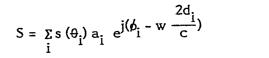
- s(θ i) : gain de la voie somme à l'angle θi ;
- d(θ i) : gain de la voie différence à l'angle θi ;
- ai: amplitude relative au iemeréflecteur ;
- φi déphasage introduit par le jèmeréflecteur ;
- di: distance entre le radar et le ièmeréflecteur ;
- Ψ: phase parasite introduite entre les voies Σ et A par les circuits hyperfréquence de formation des voies somme et différence.
- s (θ i ): gain of the sum channel at angle θ i ;
- d (θ i ): gain of the channel difference at angle θ i ;
- a i : amplitude relative to the iemoreflector;
- φ i phase shift introduced by the jem reflector;
- d i : distance between the radar and the ith reflector;
- Ψ: parasitic phase introduced between channels Σ and A by the microwave circuits for forming the sum and difference channels.
II est également connu que, dans le cas particulier du plan élévation, la phase parasite Ψ entre les voies somme et différence peut être évaluée de la façon suivante. Soit P = S x D* 

Si l'on effectue le calcul de la valeur moyenne de P sur différentes cases distance du radar, 2d.. la phase φij - w![]()
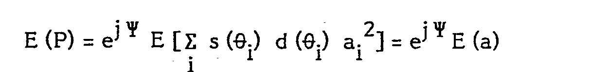
![]()
Le terme "a" est réel, mais est a priori de signe inconnu à cause des facteurs d (θ i) qui peuvent être positifs ou négatifs. En effet si l'on se reporte à la figure 2 qui représente l'allure des diagrammes somme et différence, Σ et Δ, dans le plan azimut ou dans le plan élévation, le diagramme somme présente un maximum dans la direction de l'axe de l'antenne, alors que le diagramme différence A présente au contraire un minimum dans cette direction, et est, de part et d'autre de cette direction, soit en phase (Δ+) soit en opposition de phase (A-) avec Σ.The term "a" is real, but is a priori of unknown sign because of the factors d (θ i ) which can be positive or negative. Indeed if we refer to Figure 2 which represents the shape of the sum and difference diagrams, Σ and Δ, in the azimuth plane or in the elevation plane, the sum diagram presents a maximum in the direction of the axis of the antenna, while the difference diagram A has on the contrary a minimum in this direction, and is, on either side of this direction, either in phase (Δ +) or in phase opposition (A-) with Σ.
Le moyennage de P ne permet alors a priori d'estimer la phase Ψ qu'au signe près.The averaging of P then allows a priori to estimate the phase Ψ only to the nearest sign.
Or il se trouve que dans le plan élévation, cette ambiguïté de signe peut être levée de façon relativement simple car le signe de d (θ i) est alors lié au rang de la case distance considérée, étant négatif pour les cases distance les plus proches et positif pour les cases distance les plus éloignées. En effectuant le moyennage de P sur les différentes cases distance, on obtient alors, après correction du signe en fonction de la case distance considérée, une estimation de la phase Ψ sans ambiguïté de signe.Now it turns out that in the elevation plane, this sign ambiguity can be removed relatively simply because the sign of d (θ i ) is then linked to the rank of the distance box considered, being negative for the closest distance boxes and positive for the most distant distance boxes. By averaging P over the different distance boxes, we then obtain, after correction of the sign according to the distance box considered, an unambiguous estimate of the phase Ψ.
La présente invention telle que définie dans les revendications a pour objet un procédé d'estimation de la phase parasite Ψ permettant de lever ces ambiguïtés de signe également dans le plan azimut, et dont le principe est également applicable à l'estimation de la phase parasite Ψ dans le plan élévation, ainsi qu'à l'estimation de la phase différentielle δΨ entre les plans azimut et élévation, cette dernière possibilité constituant par ailleurs, comme on le verra par la suite, la base d'une autre méthode d'estimation de la phase parasite dans le plan azimut.The present invention as defined in the claims relates to a method for estimating the parasitic phase Ψ making it possible to remove these ambiguities of sign also in the azimuth plane, and the principle of which is also applicable to the estimation of the parasitic phase Ψ in the elevation plane, as well as in the estimation of the differential phase δΨ between the azimuth and elevation planes, this latter possibility also constituting, as will be seen below, the basis of another estimation method of the parasitic phase in the azimuth plane.
D'autres objets et caractéristiques de la présente invention apparaîtront plus clairement à la lecture de la description suivante d'exemples de réalisation, faite en relation avec les dessins ci-annexés dans lesquels :
- - la figure 1 montre schématiquement la formation des voies somme et différence en azimut et en élévation dans un radar de type monopulse ;
- - la figure 2 montre la forme des diagrammes somme et différence d'un radar monopulse dans le plan azimut ou dans le plan élévation ;
- - la figure 3 illustre le balayage de l'antenne radar, suivant l'invention ;
- - la figure 4 est un schéma synoptique du traitement effectué suivant l'invention ;
- - la figure 5 est un schéma du détecteur de produit utilisé dans le traitement suivant l'invention.
- - Figure 1 schematically shows the formation of sum and difference channels in azimuth and elevation in a radar of the monopulse type;
- - Figure 2 shows the form of the sum and difference diagrams of a monopulse radar in the azimuth plane or in the elevation plane;
- - Figure 3 illustrates the scanning of the radar antenna according to the invention;
- - Figure 4 is a block diagram of the processing carried out according to the invention;
- - Figure 5 is a diagram of the product detector used in the treatment according to the invention.
L'invention est utilisée sur un système radar à émission cohérente ou non cohérente, polarisée circulairement, capable de recevoir et de discriminer polarisation circulaire droite et polarisation circulaire gauche. Pour fixer les idées dans ce qui suit, les voies azimut recevront la polarisation droite tandis que les voies élévation reçoivent la polarisation gauche ; l'inverse serait également possible.The invention is used on a radar system with coherent or non-coherent emission, circularly polarized, capable of receiving and discriminating right circular polarization and left circular polarization. To fix the ideas in what follows, the azimuth channels will receive the right polarization while the elevation channels will receive the left polarization; the reverse would also be possible.
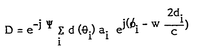
Ainsi en se référant à une phase absolue hypothétique les signaux somme Σa et Σe, respectivement en azimut et en élévation, et les signaux différence Aa et Δe, respectivement en azimut et en élévation, s'écrivent :


A partir des signaux somme et différence Σa, Σe, Δa' Δe, les expressions suivantes sont calculées :![]()
![]()
![]()
![]()
Une unité de temps étant fixée suffisamment petite pour que le déphasage entre voies puisse être considéré comme constant, on a à un instant k:

On notera que le calcul des expressions S et D permet, entre autres, de s'affranchir de la composante de phase non cohérente ϕt.It will be noted that the computation of the expressions S and D allows, inter alia, to be freed from the non-coherent phase component ϕt.
On calcule alors l'expression : [S(k+1) - S(k-1)]D* (k) où k-1, k et k+1 désignent trois instants successifs. On a :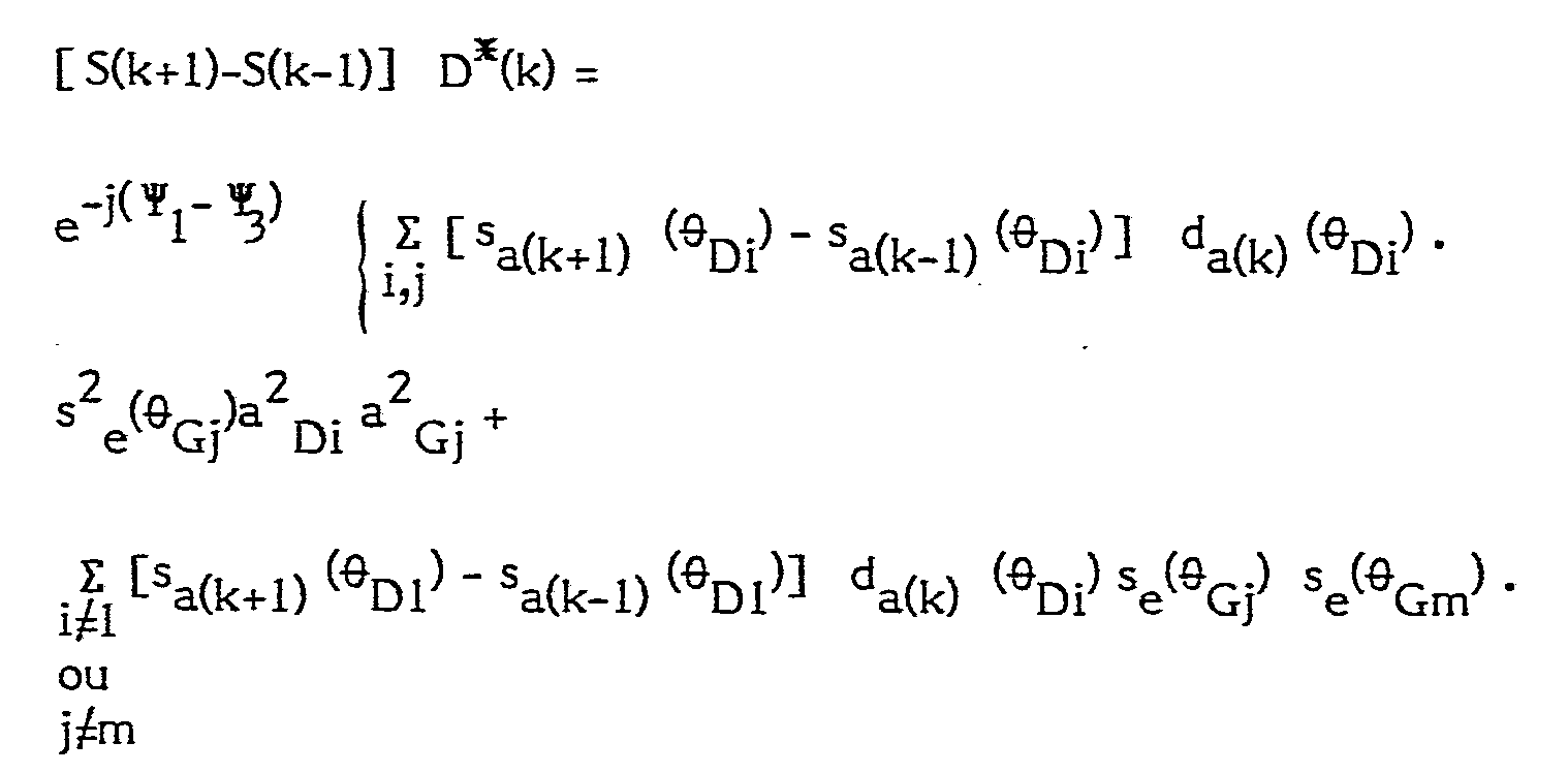

![]()
![]()
Dans l'expression Σ bn eiϕ n, les facteurs bn sont affectés d'un terme de phase ϕn qui, pouvant être considéré comme aléatoire, diparaîtra par moyennage de l'expression : [S(k+1) S(k-1)] D*(k) sur plusieurs mesures successives de Σa, Δa, Σe, Δe effectuées par le radar et correspondant à plusieurs instants k successifs.In the expression Σ b n eiϕ n, the factors b n are assigned a phase term ϕ n which, which can be considered as random, will disappear by averaging the expression: [S (k + 1) S (k -1)] D * (k) on several successive measurements of Σa, Δa, Σe, Δe taken by the radar and corresponding to several successive instants k.
La notion de mesures effectuées par le radar se rapporte à la notion de cases distance et d'impulsions. Pour une case distance donnée, le moyennage est ensuite effectué sur plusieurs impulsions successives, et le moyennage est ensuite effectué sur plusieurs cases distance. Grâce à la double polarisation les facteurs non affectés d'un tel terme de phase sont limités à l'expression "a" pour laquelle on a l'égalité i = I et j = m. Tous les autres cas (tels que i = j ou m =I) sont en effet exclus car ils correspondraient à des réflecteurs individuels qui renverraient les deux types de polarisation : droite et gauche, c'est-à-dire qui seraient à la fois du type dièdre (nombre pair de réflexions successives, et du type tièdre (nombre impair de réglexions successives).The notion of radar measurements relates to the notion of distance and pulse boxes. For a given distance cell, the averaging is then carried out on several successive pulses, and the averaging is then carried out on several distance cells. Thanks to the double polarization the factors not affected by such a phase term are limited to the expression "a" for which there is the equality i = I and j = m. All the other cases (such as i = j or m = I) are indeed excluded because they would correspond to individual reflectors which would return the two types of polarization: right and left, that is to say which would be at the same time of the dihedral type (even number of successive reflections, and of the lukewarm type (odd number of successive reflections).
L'invention permet donc de conserver toute l'information angulaire comprise dans les signaux reçus, tout en éliminant la non cohérence de l'émission, en les référençant à la réponse à la même impulsion de réflecteurs différents. Ceci est réalisé grâce à la combinaison du calcul des expressions S et D et de la double polarisation.The invention therefore makes it possible to conserve all the angular information included in the signals received, while eliminating the non-coherence of the transmission, by referencing them to the response to the same pulse of different reflectors. This is achieved by the combination of the calculation of expressions S and D and the double polarization.
/Au cours du développement précédent il a été fait l'hypothèse importante qu'entre les instants k-1 et k + 1 les angles d'élévation θe(en l'occurrence θG puisque l'on considère dans cet exemple le cas où les voies azimut reçoivent la polatisation droite tandis que les voies élévation reçoivent la polarisation gauche) sont invariants, ce qui permet leur mise en facteur commun dans l'expression "a". Cette hypothèse est raisonnable dans le cas d'un radar fixe ou d'un radar embarqué si l'unité de temps est suffisamment petite pour que l'avancement de la plate-forme ne change pas la géométrie du système./ During the previous development it was made the important assumption that between the instants k-1 and k + 1 the elevation angles θ e (in this case θ G since we consider in this example the case where the azimuth channels receive the right polarization while the elevation channels receive the left polarization) are invariant, which allows them to be put into common factor in the expression "a". This assumption is reasonable in the case of a fixed radar or an on-board radar if the time unit is small enough so that the advancement of the platform does not change the geometry of the system.
L'invention est par ailleurs utilisée dans un système radar à balayage en azimut, la vitesse de rotation de l'antenne (en azimut) étant fixée à une valeur telle que les lobes Δ - et Δ + à l'instant k coïncident respectivement avec le lobe Σ à l'instant k - 1, comme représenté sur la figure 3.The invention is also used in an azimuth scanning radar system, the antenna rotation speed (in azimuth) being fixed at a value such that the lobes Δ - and Δ + at the instant k coincide respectively with the lobe Σ at time k - 1, as shown in FIG. 3.
Dans ces conditions le produit [Sa(k+1)(θ Di) -sa(k-1)(θ Di)] da(k) (θ Di) est positif pour tout réflecteur élémentaire "i". En effet, si on considère par exemple un réflecteur élémentaire qui se trouve à l'instant k sur le lobe A +, on a alors da(k) qui est positif, sa(k+1 )qui est également positif ; il en serait de même pour un réflecteur élémentaire qui serait à l'instant k sur le lobe Δ-.Under these conditions the product [Sa (k + 1) (θ Di) -s a (k-1) (θ Di)] da (k) (θ Di) is positive for any elementary reflector "i". Indeed, if we consider for example an elementary reflector which is at the instant k on the lobe A +, we then have d a ( k ) which is positive, s a (k + 1) which is also positive; it would be the same for an elementary reflector which would be at the instant k on the lobe Δ-.
La vitesse de rotation de l'antenne en azimut n'est pas critique et pourrait être choisie différemment. Le choix proposé semble cependant optimal en ce qu'il donne les plus grandes valeurs de la différence (Sa(k+ 1) - Sa(k-1)).The rotational speed of the antenna in azimuth is not critical and could be chosen differently. The choice proposed however seems optimal in that it gives the largest values of the difference (Sa ( k + 1) - S a (k-1) ).
Le facteur "a" s'écrit donc comme la somme d'un grand nombre de réels positifs. Au contraire, les facteurs bn sont affectés d'un terme de phase ϕn qui peut être considéré comme aléatoire.The factor "a" is therefore written as the sum of a large number of positive reals. On the contrary, the factors bn are assigned a phase term ϕ n which can be considered as random.
L'examen de plusieurs mesures successives de [S(k+ 1) - (S(k-1)] D* (k) permet par moyennage d'estimer la correction de phase ![]()
![]()
![]()
![]()
L'adaptation de la période de répétition des mesures effectuées par le radar (correspondant à la notion de cases distances et d'impulsions) et de la période de répétition des instants k, c'est-à-dire de la vitesse de balayage de l'antenne, peut être faite de diverses façons, par exemple en choisissant convenablement la période de répétition des impulsions, ou bien en réalisant un post-intégration sur plusieurs impulsions.The adaptation of the period of repetition of the measurements carried out by the radar (corresponding to the notion of distance and pulse boxes) and of the period of repetition of the instants k, that is to say of the scanning speed of the antenna can be made in various ways, for example by suitably choosing the repetition period of the pulses, or else by performing post-integration on several pulses.
On a représenté sur la figure 5 un schéma du détecteur de produit utilisé dans le traitement effectué suivant l'invention pour estimer la phase parasite entre les voies somme et différence en azimut.FIG. 5 shows a diagram of the product detector used in the treatment carried out according to the invention to estimate the parasitic phase between the sum and difference channels in azimuth.
Les signaux Σa, Aa et Σe sont appliqués à l'entrée de ce détecteur de produit qui calcule les expressions :![]()
![]()
![]()
![]()
II est à noter que l'on n'utilise pas S et D aux mêmes instants, puisque seul le produit [S(k+1) - S(k-1)] D*(k) importe. II est donc possible de n'utiliser qu'un seul détecteur de produit, adressé successivement, grâce à un commutateur 10 par les voies Ea et Ec puis Δaet Σe.It should be noted that S and D are not used at the same times, since only the product [S (k + 1) - S (k-1)] D * (k) matters. It is therefore possible to use only one product detector, addressed successively, by means of a
Les grandeurs S et D sont des grandeurs complexes qui peuvent s'écrire sous la forme : I + j Q où I et Q désignent respectivement leur partie réelle et leur partie imaginaire ; les grandeurs I et Q sont obtenues sur deux sorties du détecteur de produit.The quantities S and D are complex quantities which can be written in the form: I + j Q where I and Q respectively designate their real part and their imaginary part; the quantities I and Q are obtained on two outputs of the product detector.
Les autres étapes du procédé peuvent être réalisées grâce à un logiciel adapté.The other steps of the process can be carried out using suitable software.
Dans ce qui précède, l'invention a été décrite pour l'estimation de la phase parasite entre les voies somme et différence en azimut. Le principe de l'invention est néanmoins applicable à l'estimation de la phase parasite entre les voies somme et différence en élévation.In the foregoing, the invention has been described for the estimation of the parasitic phase between the sum and difference channels in azimuth. The principle of the invention is nevertheless applicable to the estimation of the parasitic phase between the sum and difference in elevation channels.
Dans ce cas on calculerait les expressions :![]()
![]()
![]()
![]()
La contrainte sur le balayage deviendrait alors une contrainte sur le balayage en élévation, et l'hypothèse qu'entre les instants k-1, k et k+1 les angles d'azimut sont invariants devrait également être faite.The constraint on the scan would then become a constraint on the elevation scan, and the assumption that between the instants k-1, k and k + 1 the azimuth angles are invariant should also be made.
Comme on va le voir maintenant, le principe de l'invention est également applicable à l'estimation de la phase parasite différentielle Ψa - Ψe, où Ψa et Ψe désignent respectivement la phase parasite en azimut et en élévation. L'estimation de cette phase parasite différentielle peut présenter un intérêt pour les raisons suivantes.As we will see now, the principle of the invention is also applicable to the estimation of the differential parasitic phase Ψ a - Ψ e , where Ψ a and Ψ e denote respectively the parasitic phase in azimuth and in elevation. The estimation of this differential parasitic phase may be of interest for the following reasons.
Dans le cas notamment d'un radar porté par un missile dont la vitesse supersonique décroît en cours de vol jusqu'à des valeurs subsoniques, les écarts importants de température entre le début et la fin de la mission entraînent une variation des phases parasites en azimut et en élévation.In the case in particular of a radar carried by a missile whose supersonic speed decreases during flight to subsonic values, the significant temperature differences between the start and the end of the mission cause a variation of the parasitic phases in azimuth and in elevation.
Or, les contraintes de balayage d'antenne exposées précédemment font que l'estimation d'un facteur correctif de phase n'est pas réalisable durant toute la période d'utilisation et de traitement du radar.However, the antenna scanning constraints described above mean that the estimation of a phase correction factor cannot be carried out during the entire period of use and processing of the radar.
Partant de la constatation que les quatre récepteurs (deux en azimut, et deux en élévation) sont physiquement proches les uns des autres et thermiquement solidaires, donc que les variations de Ψa et Ψe seront similaires, il suffit alors d'évaluer Ψa et Ψe lors d'une phase dite de calibration (préalable à tout fonctionnement en mode recherche ou poursuite) et de calculer la différence Ψa - Ψe qui restera constante pendant toute la durée du vol. En phase poursuite il est toujours possible comme rappelé dans l'introduction de calculer Ψe par un mode d'evaluation qui n'offre aucune contrainte de position d'antenne ou de fréquence. Il est alors possible d'en déduire Ψa.Starting from the observation that the four receivers (two in azimuth, and two in elevation) are physically close to each other and thermally interdependent, therefore that the variations of Ψ a and Ψ e will be similar, it suffices then to evaluate Ψ a and Ψ e during a so-called calibration phase (prior to any operation in search or pursuit mode) and to calculate the difference Ψ a - Ψ e which will remain constant throughout the duration of the flight. In the tracking phase it is always possible, as recalled in the introduction, to calculate Ψ e by an evaluation mode which offers no constraint on antenna position or frequency. It is then possible to deduce Ψa from it.
Cependant une évaluation successive de Ψa et Ψe au cours de la phase de calibration risque d'induire une erreur sur Ψa - Ψe dans la mesure où la température peut avoir changé entre les deux évaluations. De plus, la phase de calibration a une durée importante par rapport à la durée totale de la mission d'un missile courte portée.However, a successive evaluation of Ψ a and Ψ e during the calibration phase risks inducing an error on Ψ a - Ψ e since the temperature may have changed between the two evaluations. In addition, the calibration phase has a significant duration compared to the total duration of the mission of a short-range missile.
Le procédé d'estimation de phase parasite suivant l'invention permet de calculer directement la phase différentielle Ψa - Ψe sans passer par les calculs successifs de Ψa et Ψe, ce qui permet de s'affranchir du risque d'erreur précédemment cité.The parasitic phase estimation method according to the invention makes it possible to directly calculate the differential phase Ψ a - Ψ e without going through the successive calculations of Ψ a and Ψ e , which makes it possible to overcome the risk of error previously. cited.
On décrit maintenant ce procédé, appliqué à l'estimation de la phase différentielle Ψa Ψe. Comme précédemment, les signaux reçus par les quatre voies d'écartométrie s'écrivent :


- ai est l'amplitude du iéme réflecteur individuel ;
- φ est le déphasage introduit par le ième réflecteur ;
- di est la distance radar-ième réflecteur ;
- ϕt est la composante de phase non cohérente qui change d'impulsion à impulsion ;
- Ψ1, Ψ2, Ψ3, Ψ4 sont les phases parasites introduites sur les quatre voies de réception.
- a i is the amplitude of the ith individual reflector;
- φ is the phase shift introduced by the ith reflector;
- d i is the radar-th reflector distance;
- ϕt is the non-coherent phase component which changes from pulse to pulse;
- Ψ 1 , Ψ 2 , Ψ 3 , Ψ 4 are the parasitic phases introduced on the four reception channels.
Suivant la même méthode que précédemment, un détecteur de produit calcule.:![]()
![]()
![]()
![]()
![]()
![]()
![]()
![]()
Or la vitesse de rotation en azimut du radar a été choisie de telle façon que le produit : [sa(k + 1)(θ Di) sa(k-1)(θ Di] da(k)(θ Di) soit positif pour tous les réflecteurs élémentaires. De plus se(θ Gj) est positif, a2Dia2Gj est positif, et de (θ Gj) est négatif pour les cases distances les plus proches, et est positif pour les cases distances les plus éloignées.Now the speed of rotation in azimuth of the radar was chosen in such a way that the product: [s a (k + 1) (θ Di ) s a (k-1) (θ Di ] d a (k) (θ D i) is positive for all the elementary reflectors. Furthermore s e (θ G j) is positive, a 2 Dia 2 Gj is positive, and de (θ G j) is negative for the closest distance boxes, and is positive for the most distant distance boxes.
L'ambiguïté de signe peut donc être levée et corrigée de telle façon que le facteur "a" soit la somme d'un grand nombre de réels positifs.The ambiguity of the sign can therefore be removed and corrected in such a way that the factor "a" is the sum of a large number of positive reals.
L'examen de plusieurs mesures successives de [ S(k + 1)-S(k-1)] D* (k) permet par moyennage d'estimer la correction de phase ![]()
![]()
![]()
![]()
![]()
![]()
![]()
![]()
La moyenne est calculée sur plusieurs cases distances et plusieurs impulsions de façon à obtenir la précision désirée.The average is calculated over several distance boxes and several pulses so as to obtain the desired precision.
Claims (3)


Applications Claiming Priority (2)
| Application Number | Priority Date | Filing Date | Title |
|---|---|---|---|
| FR8602877 | 1986-02-28 | ||
| FR8602877A FR2595144B1 (en) | 1986-02-28 | 1986-02-28 | SUM AND DIFFERENCE SIGNAL PROCESSING OF A MONOPULSE-TYPE RADAR, WITH A VIEW TO ESTIMATING THE INTERFERENCE PHASE INTRODUCED BETWEEN THESE SIGNALS BY THE SUM AND DIFFERENCE PATHWAY HYPERFREQUENCY CIRCUITS |
Publications (2)
| Publication Number | Publication Date |
|---|---|
| EP0237404A1 true EP0237404A1 (en) | 1987-09-16 |
| EP0237404B1 EP0237404B1 (en) | 1990-08-08 |
Family
ID=9332663
Family Applications (1)
| Application Number | Title | Priority Date | Filing Date |
|---|---|---|---|
| EP87400426A Expired - Lifetime EP0237404B1 (en) | 1986-02-28 | 1987-02-26 | Method of processing sum and difference signals in a monopulse radar for estimating the parasitic phase between these signals caused by the hf circuits forming sum and difference channels |
Country Status (4)
| Country | Link |
|---|---|
| US (1) | US4713666A (en) |
| EP (1) | EP0237404B1 (en) |
| DE (1) | DE3764121D1 (en) |
| FR (1) | FR2595144B1 (en) |
Cited By (2)
| Publication number | Priority date | Publication date | Assignee | Title |
|---|---|---|---|---|
| EP0429090A2 (en) * | 1989-11-24 | 1991-05-29 | SELENIA INDUSTRIE ELETTRONICHE ASSOCIATE S.p.A. | Device for the automatic correction of the differential error, preferably for a monopulse radar receiver |
| EP0499375A1 (en) * | 1991-02-11 | 1992-08-19 | Hughes Aircraft Company | Radar guidance system correcting hardware induced channel-to-channel phase errors |
Families Citing this family (8)
| Publication number | Priority date | Publication date | Assignee | Title |
|---|---|---|---|---|
| FR2609224B1 (en) * | 1986-12-30 | 1989-04-07 | Thomson Csf | DEVICE AND METHOD FOR TRANSMITTING AND / OR ACQUIRING DATA USING TWO CROSS POLARIZATIONS OF AN ELECTROMAGNETIC WAVE AND MAGNETIC RECORDING DEVICE |
| US5808578A (en) * | 1996-12-20 | 1998-09-15 | Barbella; Peter F. | Guided missile calibration method |
| US5986605A (en) * | 1997-05-23 | 1999-11-16 | Raytheon Company | Method for improving monopulse processing of aperture segment outputs |
| DE10146643C1 (en) * | 2001-09-21 | 2003-08-14 | Eads Deutschland Gmbh | Procedure for calibrating the radar signals at the subapertures of the antenna of a two-channel SAR / MTI radar system |
| JP5352959B2 (en) * | 2007-03-16 | 2013-11-27 | 富士通株式会社 | Direct sequence spread spectrum radar, method used in radar and computer program |
| CN102323579A (en) * | 2011-08-12 | 2012-01-18 | 西安天伟电子系统工程有限公司 | Height measurement method for continuous wave search radar |
| CN104362437B (en) * | 2014-11-22 | 2018-07-13 | 成都锦江电子系统工程有限公司 | S-band single pulse self-tracking antenna system |
| EP3255731B1 (en) * | 2015-02-02 | 2020-11-04 | Mitsubishi Electric Corporation | Antenna device and antenna excitation method |
Citations (3)
| Publication number | Priority date | Publication date | Assignee | Title |
|---|---|---|---|---|
| US3794998A (en) * | 1972-04-26 | 1974-02-26 | Raytheon Co | Monopulse radar receiver with error correction |
| EP0038734A1 (en) * | 1980-04-23 | 1981-10-28 | Thomson-Csf | Apparatus for normalizing the gradient of the off-boresight measurement by radar and air-earth radar comprising such an apparatus |
| US4368468A (en) * | 1980-12-22 | 1983-01-11 | Westinghouse Electric Corp. | Monopulse radio receiver compensation apparatus |
Family Cites Families (3)
| Publication number | Priority date | Publication date | Assignee | Title |
|---|---|---|---|---|
| US4568940A (en) * | 1981-12-22 | 1986-02-04 | Hughes Aircraft Company | Dual-mode radar receiver |
| FR2555319B1 (en) * | 1983-11-23 | 1987-07-31 | Trt Telecom Radio Electr | FREQUENCY MODULATED SINGLE-PULSE CONTINUOUS WAVE RADAR SYSTEM WITH IMPROVED AXIS STABILITY |
| US4646095A (en) * | 1985-08-16 | 1987-02-24 | Raytheon Company | Method of resolving closely spaced targets |
-
1986
- 1986-02-28 FR FR8602877A patent/FR2595144B1/en not_active Expired
-
1987
- 1987-02-24 US US07/017,627 patent/US4713666A/en not_active Expired - Fee Related
- 1987-02-26 EP EP87400426A patent/EP0237404B1/en not_active Expired - Lifetime
- 1987-02-26 DE DE8787400426T patent/DE3764121D1/en not_active Expired - Fee Related
Patent Citations (3)
| Publication number | Priority date | Publication date | Assignee | Title |
|---|---|---|---|---|
| US3794998A (en) * | 1972-04-26 | 1974-02-26 | Raytheon Co | Monopulse radar receiver with error correction |
| EP0038734A1 (en) * | 1980-04-23 | 1981-10-28 | Thomson-Csf | Apparatus for normalizing the gradient of the off-boresight measurement by radar and air-earth radar comprising such an apparatus |
| US4368468A (en) * | 1980-12-22 | 1983-01-11 | Westinghouse Electric Corp. | Monopulse radio receiver compensation apparatus |
Cited By (4)
| Publication number | Priority date | Publication date | Assignee | Title |
|---|---|---|---|---|
| EP0429090A2 (en) * | 1989-11-24 | 1991-05-29 | SELENIA INDUSTRIE ELETTRONICHE ASSOCIATE S.p.A. | Device for the automatic correction of the differential error, preferably for a monopulse radar receiver |
| EP0429090A3 (en) * | 1989-11-24 | 1991-12-04 | Selenia Industrie Elettroniche Associate S.P.A. | Device for the automatic correction of the differential error, preferably for a monopulse radar receiver |
| EP0499375A1 (en) * | 1991-02-11 | 1992-08-19 | Hughes Aircraft Company | Radar guidance system correcting hardware induced channel-to-channel phase errors |
| TR25707A (en) * | 1991-02-11 | 1993-09-01 | Hughes Aircraft Co | EQUIPMENT ORIGINAL, CHANNEL-TO-CHANNEL PHASE ERRORS WITH RADAR REMOVAL SYSTEM. |
Also Published As
| Publication number | Publication date |
|---|---|
| US4713666A (en) | 1987-12-15 |
| DE3764121D1 (en) | 1990-09-13 |
| FR2595144B1 (en) | 1988-05-13 |
| FR2595144A1 (en) | 1987-09-04 |
| EP0237404B1 (en) | 1990-08-08 |
Similar Documents
| Publication | Publication Date | Title |
|---|---|---|
| EP0063517B1 (en) | Passive range-finding system | |
| FR2692681A1 (en) | A method of discriminating obstacles from a radar, and applications. | |
| EP2574957B1 (en) | Method for estimating the unambiguous Doppler frequency of a moving target, in particular marine, and radar implementing said method | |
| FR2501868A1 (en) | APPARATUS FOR DETERMINING THE PRESENCE OF MULTIPLE REFLECTION CONDITIONS DURING TARGET PURSUIT USING RADAR | |
| FR2517435A1 (en) | MISSILE GUIDING SYSTEM WITH CARD EQUALIZER HORIZONTAL AND VERTICAL BRAND CONTROL | |
| FR2669117A1 (en) | METHOD FOR RESOLVING AN AMBIGUUITE DURING DETERMINATION OF ANTENNA ANGLE AND DOPPLER FREQUENCY IN AN OPENING SYNTHESIS RADAR | |
| EP0237404B1 (en) | Method of processing sum and difference signals in a monopulse radar for estimating the parasitic phase between these signals caused by the hf circuits forming sum and difference channels | |
| EP0143497B1 (en) | Axis-stable fmcw monopulse radar system | |
| US5559516A (en) | Dual cancellation interferometric AMTI radar | |
| FR2709834A1 (en) | Method and device for detecting and locating obstacles in the environment of a vehicle | |
| EP3022573B1 (en) | Device for detecting electromagnetic signals | |
| EP2455778A1 (en) | Method for estimating the angular position of a target by radar detection and radar implementing the method | |
| EP0014619B1 (en) | Dynamic non-linear filter device for angle measurement noise in a radar, and radar unit comprising same | |
| EP3391072A1 (en) | Method for locating sources emitting electromagnetic pulses | |
| EP2990824B1 (en) | Sonar method and device for determining the speed of movement of a marine vehicle relative to the seabed | |
| EP1695115A1 (en) | Device for avoiding obstacles for high-speed multi-hulled watercraft | |
| EP0026134B1 (en) | Device for increasing the angular resolution of an airborne doppler radar | |
| FR2632420A1 (en) | METHOD AND APPARATUS FOR COMPENSATING FOR SCALE SPEED IN COHERENT DOPPLER RADAR WITH VARIABLE AMBIGE SPEED | |
| EP1324065B1 (en) | Method for passively finding the position of a target and especially for air-air locating | |
| FR3070766A1 (en) | IMPROVED RADAR SYSTEM FOR ENHANCED TRACKING | |
| FR2998975A1 (en) | Method for filtering ambiguities in retrodiffused radar signal of multichannel radar system on-board aircraft, involves calculating filter to be applied to matrix to minimize power of unwanted echoes within retrodiffused radar signal | |
| EP0335753B1 (en) | Radar for correcting artillery fire | |
| FR2895089A1 (en) | METHOD AND DEVICE FOR SIGNAL PROCESSING FOR ANGULAR DETERMINATION USING HYPERFREQUENCY MOTION SENSORS | |
| FR2725526A1 (en) | RADAR MONOPULSE AIR-GROUND TYPE AIRCRAFT | |
| FR2550347A1 (en) | Improvements to pulsed Doppler radars |
Legal Events
| Date | Code | Title | Description |
|---|---|---|---|
| PUAI | Public reference made under article 153(3) epc to a published international application that has entered the european phase |
Free format text: ORIGINAL CODE: 0009012 |
|
| AK | Designated contracting states |
Kind code of ref document: A1 Designated state(s): DE GB IT NL |
|
| 17P | Request for examination filed |
Effective date: 19880220 |
|
| RAP3 | Party data changed (applicant data changed or rights of an application transferred) |
Owner name: THOMSON-CSF |
|
| 17Q | First examination report despatched |
Effective date: 19891222 |
|
| GRAA | (expected) grant |
Free format text: ORIGINAL CODE: 0009210 |
|
| AK | Designated contracting states |
Kind code of ref document: B1 Designated state(s): DE GB IT NL |
|
| PG25 | Lapsed in a contracting state [announced via postgrant information from national office to epo] |
Ref country code: NL Effective date: 19900808 |
|
| ITF | It: translation for a ep patent filed |
Owner name: JACOBACCI & PERANI S.P.A. |
|
| REF | Corresponds to: |
Ref document number: 3764121 Country of ref document: DE Date of ref document: 19900913 |
|
| GBT | Gb: translation of ep patent filed (gb section 77(6)(a)/1977) | ||
| NLV1 | Nl: lapsed or annulled due to failure to fulfill the requirements of art. 29p and 29m of the patents act | ||
| PLBE | No opposition filed within time limit |
Free format text: ORIGINAL CODE: 0009261 |
|
| STAA | Information on the status of an ep patent application or granted ep patent |
Free format text: STATUS: NO OPPOSITION FILED WITHIN TIME LIMIT |
|
| 26N | No opposition filed | ||
| ITTA | It: last paid annual fee | ||
| PGFP | Annual fee paid to national office [announced via postgrant information from national office to epo] |
Ref country code: GB Payment date: 19950119 Year of fee payment: 9 |
|
| PGFP | Annual fee paid to national office [announced via postgrant information from national office to epo] |
Ref country code: DE Payment date: 19950120 Year of fee payment: 9 |
|
| PG25 | Lapsed in a contracting state [announced via postgrant information from national office to epo] |
Ref country code: GB Effective date: 19960226 |
|
| GBPC | Gb: european patent ceased through non-payment of renewal fee |
Effective date: 19960226 |
|
| PG25 | Lapsed in a contracting state [announced via postgrant information from national office to epo] |
Ref country code: DE Effective date: 19961101 |
|
| PG25 | Lapsed in a contracting state [announced via postgrant information from national office to epo] |
Ref country code: IT Free format text: LAPSE BECAUSE OF NON-PAYMENT OF DUE FEES;WARNING: LAPSES OF ITALIAN PATENTS WITH EFFECTIVE DATE BEFORE 2007 MAY HAVE OCCURRED AT ANY TIME BEFORE 2007. THE CORRECT EFFECTIVE DATE MAY BE DIFFERENT FROM THE ONE RECORDED. Effective date: 20050226 |