EP0228048A2 - Customer programmable real-time system - Google Patents
Customer programmable real-time system Download PDFInfo
- Publication number
- EP0228048A2 EP0228048A2 EP86117756A EP86117756A EP0228048A2 EP 0228048 A2 EP0228048 A2 EP 0228048A2 EP 86117756 A EP86117756 A EP 86117756A EP 86117756 A EP86117756 A EP 86117756A EP 0228048 A2 EP0228048 A2 EP 0228048A2
- Authority
- EP
- European Patent Office
- Prior art keywords
- instructions
- signal
- state
- program routine
- program
- Prior art date
- Legal status (The legal status is an assumption and is not a legal conclusion. Google has not performed a legal analysis and makes no representation as to the accuracy of the status listed.)
- Withdrawn
Links
Images


Classifications
-
- H—ELECTRICITY
- H04—ELECTRIC COMMUNICATION TECHNIQUE
- H04Q—SELECTING
- H04Q3/00—Selecting arrangements
- H04Q3/42—Circuit arrangements for indirect selecting controlled by common circuits, e.g. register controller, marker
- H04Q3/54—Circuit arrangements for indirect selecting controlled by common circuits, e.g. register controller, marker in which the logic circuitry controlling the exchange is centralised
- H04Q3/545—Circuit arrangements for indirect selecting controlled by common circuits, e.g. register controller, marker in which the logic circuitry controlling the exchange is centralised using a stored programme
-
- G—PHYSICS
- G06—COMPUTING; CALCULATING OR COUNTING
- G06F—ELECTRIC DIGITAL DATA PROCESSING
- G06F8/00—Arrangements for software engineering
- G06F8/30—Creation or generation of source code
- G06F8/31—Programming languages or programming paradigms
-
- G—PHYSICS
- G06—COMPUTING; CALCULATING OR COUNTING
- G06F—ELECTRIC DIGITAL DATA PROCESSING
- G06F3/00—Input arrangements for transferring data to be processed into a form capable of being handled by the computer; Output arrangements for transferring data from processing unit to output unit, e.g. interface arrangements
- G06F3/16—Sound input; Sound output
-
- H—ELECTRICITY
- H04—ELECTRIC COMMUNICATION TECHNIQUE
- H04Q—SELECTING
- H04Q3/00—Selecting arrangements
- H04Q3/0016—Arrangements providing connection between exchanges
- H04Q3/0029—Provisions for intelligent networking
- H04Q3/0033—Provisions for intelligent networking customer-controlled
-
- H—ELECTRICITY
- H04—ELECTRIC COMMUNICATION TECHNIQUE
- H04Q—SELECTING
- H04Q2213/00—Indexing scheme relating to selecting arrangements in general and for multiplex systems
- H04Q2213/13548—Indexing scheme relating to selecting arrangements in general and for multiplex systems call modeling, e.g. Basic Call State Model
-
- Y—GENERAL TAGGING OF NEW TECHNOLOGICAL DEVELOPMENTS; GENERAL TAGGING OF CROSS-SECTIONAL TECHNOLOGIES SPANNING OVER SEVERAL SECTIONS OF THE IPC; TECHNICAL SUBJECTS COVERED BY FORMER USPC CROSS-REFERENCE ART COLLECTIONS [XRACs] AND DIGESTS
- Y10—TECHNICAL SUBJECTS COVERED BY FORMER USPC
- Y10S—TECHNICAL SUBJECTS COVERED BY FORMER USPC CROSS-REFERENCE ART COLLECTIONS [XRACs] AND DIGESTS
- Y10S379/00—Telephonic communications
- Y10S379/914—Programmable telephone component
Definitions
- This invention relates to control of real-time systems and, in particular, to the control of a telecommunication switching system by utilizing a software development environment and a language that allows a nonprocedural writing of programs enabling a customer to modify the functions performed by the switching system in real time.
- the ability to modify system functions for a given customer is often referred to in telecommunication switching technology as customizing the features or services of the system, and the ability of a customer to make such changes is referred to as customer programmability.
- customer programmability The definition of a customer with respect to telecommunication systems includes the residential or business user of such a system and a telecommunication company providing the service, such as a Regional Bell Operating Company, e.g., Ameritech, Inc. or a governmental agency such as the British Post Office. Each of these two types of customers has different requirements with respect to customer programmability.
- the problems facing the telecommunication provider in customizing services and features for a telecommunication system stem from two factors which relate to the programming language used by the manufacturer to write the programs that control this system and the software development environment.
- the first factor relates to the fact that present day telecommunication systems are controlled by a computer executing a program which is normally written in a high-level procedural language, such as C or Pascal, although many systems are still written in assembly language.
- the problem of the telecommunication systems program being written in a procedural language such as C or Pascal is that the order of execution of actions defined by the program in response to different signals from the telecommunication system is only implicit from the sequence of instructions, and the program response is not directly based on the state of the telecommunication system and the system's signals at any point in time. Because of this problem, only an expert in the program structure of the telecommunication system can make changes or add new services to the telecommunication system because it is necessary to know where in the sequence of the program instructions the changes must be made to modify existing services and to add new services.
- the second factor is that the telecommunication control programs are normally developed on a computer system different than the one utilized to control the telecommunication systems.
- These development systems are not an integral part of the telecommunication system and cannot readily transfer developed programs to the telecommunication system.
- these development systems are special purpose and require skilled administration personnel.
- One such development system is described in the article entitled, "Software Development Tools,” AT & T Technical Journal , Vol. 64, No. l, January, l985, pp. 287-304, by T. J. Pedersen, J. E. Ritacco, and J. A. Santillo.
- SDL Specification and Description Language
- the SDL language allows the telecommunication provider to describe the services and features that a telecommunication system is to provide in terms of state and telecommunication signal information. Once the telecommunication provider uses SDL for the formal description, manufacturers are free to implement that description in the language of their choice, such as CHILL or C. While the SDL approach does allow the telecommunication provider to control and specify the software development, it nevertheless still leaves the telecommunication provider dependent on the manufacturer for implementation of services and does not give the telecommunication provider the flexibility to make changes at its discretion.
- the system can assume a plurality of states and generate a plurality of signals.
- a computer system executes a first program routine to control the comminications functions of the system in order to provide a first set services.
- the computer system under control of the first program routine is directly resposnive to the system states and system signals.
- the computer system is responsive to source code instructions that define additional servcies to compile source code by execution of a second program routine.
- a third program routine controls the computer system so that the latter is responsive to the compiled source code instructions defining the additional services to update the first program routine.
- a fourth program routine is executed to activate the updated portion.
- the computer system updates the first program routine with the compiled source code instructions in such a way as not to interfere with the normal real-time control of the system.
- the computer system comprises a first processor for executing the first program routine including the updated portion and a second processor for executing the second program routine that performs the compilation.
- the fourth program routine comprises a plurality of groups of instructions each of whose execution is actuated by the occurrence of a predefined system state and signal.
- the activation of the updated portion of the first program routine is accomplished by a group of instructions of the fourth program routine responding to a system time signal for enabling the updated portion.
- a fifth program routine is provided to deactivate the updated portion of the first program upon the occurrence of a second system time signal by a group of instructions of the latter routine responding to the second time signal to generate a deactivate signal indicating that the updated portion is to be deactivated.
- the updated portion of the first program routine also contains groups of instructions each actuated by a predefined state and signal. One of the groups of instructions of the updated portion is responsive to the deactivate signal for disabling the updated portion.
- the first program routine contains a set of instructions that generates a leave signal when the present state of the system is changed to another state and another set of instructions that generates an enter signal when the other state is entered. These two signals are used in the following manner.
- a second group of instructions in the first program routine is responsive to the leave signal for performing common exit operations, and a third group of instructions is responsive to the entry signal and the other state for performing common entrance operations.
- the illustrative method allows a user to program and control a voice and data telecommunications system that can assume a plurality of states and generate a plurality of signals.
- a first processor is used to control the system executing sets of instructions each comprising basic groups of instructions, and a second processor is used for the compilation of source code instructions written in a nonprocedural language.
- the method comprises the steps of: l) controlling the system by the first processor executing the basic groups of instructions that perform individual operations in response to the present system state and system signal matching the predefined state and signal that actuate each of the groups of instructions, 2) entering a source code program that defines additional services or modifies existing services, 3) compiling the entered code into additional sets of instructions each comprising additional groups of instructions to control the first processor to perform the additional services, 4) transferring the additional sets of instructions to the first processor from the second processor, 5) updating the basic groups of instructions with the additional groups of instructions in a predefined preference relationship by the first processor, and 6) activating the additional groups of the instructions.
- the first processor has a plurality of control structures
- the method further comprises the steps of relating individually in each of the plurality of control structures ones of the groups of instructions that respond to identical system state and system signal stimuli in accordance with the predefined preference relationship, identifying one of the control structures in response to the present system state and the occurrence of one of the system signals, executing the group of instructions having the highest preference referenced by the identified control structure to perform a first service operation in the system, allowing the group of instructions having second highest preference referenced by the identified control structure to execute by the execution of one of the highest preference group of instructions, and preventing the group of instructions having the third highest preference from executing by execution of one of the second highest preference group of instructions.
- the method further provides for the deactivation and activation of the sets of instructions with the deactivation or activation being controlled by a group of instructions responding to defined system state and signal.
- each of the control structures is associated with one of the system states and each of the control structures comprises a plurality of tables each associated with one of the system signals occurring in the system state of the associated control structure and the updating step comprises the steps of: determining the table corresponding to the state and signal that actuates the execution of each additional group of instructions and storing into the determined table a reference for each of the additional groups of instructions. Also, when a set of instructions is deactivated, all references in the tables of the control structures are removed for groups of instructions contained within the deactivated set of instructions.
- the method further comprises the steps of initiating a change from the present system state to another system state by the execution of an instruction of a first group of instructions, generating a leave signal indicating the exiting from the present state, performing common exit operations before leaving the present state by the execution of a second group of instructions in response to the leave signal and the present state, generating another signal indicating the entry into the other state, and performing common entrance operations upon entering said other state by the execution of a third one of the groups of instructions in response to the enter signal and the other state.
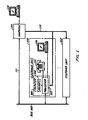
- FIG. l The telecommunication system which is the subject of this invention is illustrated in FIG. l.
- the latter system is capable of switching both packetized voice and data via bus l00.
- Each customer unit has associated with it, a telephone set for voice communication and a data terminal for data communication.
- the computer associated with each customer unit provides under program control the control functions for its associated customer unit for either a voice or data call.
- Each individual customer unit's computer is executing a program that provides customized services for the customer.
- This program is written in a novel, nonprocedural language that allows the explicit relations between state and telecommunication events to be directly programmed.
- a customer can customize his or her particular unit by interacting with the UNIX TM operating system that is controlling computer l0l to write the source code for the new service in the nonprocedural language.
- the source code is then compiled and downloaded to the customer's computer.
- the new compiled code is stored in the customer unit's computer with priority being determined at activation time.
- a telecommunication provider company could also use magnetic tape or other medium to directly load computer l0l and to subsequently have the programs transferred to the customer units.
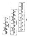
- FIG. 2 The state diagram for basic telephone service provided by the telecommunication system of FIG. l is illustrated in FIG. 2 and the accompanying source code program is shown in FIGS. 3 and 4.
- a customer using data terminal, logs on to the UNIX operating system controlling computer l0l. Then, using standard editing techniques, the customer enters a program such as illustrated in FIG. 5.
- the program illustrated in FIG. 5 provides call forwarding which allows the customer to forward calls from customer unit l02 to any other designated customer unit and allows calling party identification which allows a calling party to customer unit l02 to be identified on terminal l06.
- the program illustrated in FIG. 5 also provides for the activation and deactivation of the call forwarding feature so that the feature is activated during the working hours of the week but deactivated during nonworking hours.
- the customer After the customer has prepared the program illsutrated in FIG. 5, the customer then executes a compiler under control of the UNIX operating system that compiles the source code illustrated in FIG. 5 into compiled code which has the format illustrated in FIG. 8. The latter compiled code is then transferred to computer l04 vis bus ll0.
- the operating system controlling computer l04 is responsive to the information illustrated in FIG. 8 to execute the program illustrated in FIG. 9 on a time-shared basis such that the normal telecommunication service is not interrupted. Hence, the customer can be talking on telephone handset l05 during the course of this operation.
- the compiled code that is downloaded as illustrated in FIG. 8 is stored, upon activation, in logical signal tables such as illustrated in FIGS. 6 and 7.
- the latter tables relate all signals with the state in which each signal can occur.
- the customer can manually activate the new service by the execution of the activation command or it can be done automatically by other code, such as the code illustrated for the activation of the call forwarding feature in FIG. 5.
- the physical structure of the logical signal tables of FIGS. 6 and 7 coupled with the nonprocedural language primitives of STOP and CONTINUE allow the new services to control whether or not the original basic code is executed or prohibited from execution for each state.
- the nonprocedural language event specifiers of ENTER and LEAVE allow the programmer to be unconcerned about the problems of initializing and resetting various aspects of the telecommunication system when a state is entered or left via a plurality of state transitions.
- the nonprocedural language explicitly defines operations in terms of related state and signal information from the telecommunication system and allows the customer to easily and readily program the customer units to meet the needs of the customer.
- the actual source code is written and compiled on the UNIX operating system which is a commercially available system, the need for programmers specifically skilled in telecommunications type system is alleviated, to a large extent.
- the software system which is the subject of this invention is advantageously implemented by the hardware system illustrated in FIG. l.
- the hardware of FIG. l comprises a plurality of customer units l02 through l03.
- Each customer unit comprises a computer, a telephone handset, and a data terminal.
- Voice and data information is communicated in the form of packets via bus l00.
- Bus l00 may advantageously be of the Ethernet TM type, or it may be a packet switching system as described in U. S. Patent 4,494,230.
- Customer unit l02 comprises computer l04 which, advantageously, may be of PDP ll type manufactured by Digital Equipment Corporation, and terminal l06 may advantageously be a Teletype 54l0 terminal manufactured by the AT&T Teletype Corporation.
- Computer l04 contains units not shown for interfacing to bus l00, telephone handset l05, and terminal l06, and for performing the analog-digital conversions utilized for transmitting voice information from and to handset l05 via bus l00.
- scripts that are written in the nonprocedural language are entered via a terminal to computer l0l.
- Computer l0l compiles these scripts and then downloads interpretable representations of them via bus ll0 to the designated customer unit's memory via that unit's processor.
- Each script comprises a plurality of triples with each triple comprising a state definition, an event definition, and an action definition.
- the event definition defines which signal actuates the triple and the action definition defines the action to be taken upon the triple actuation.
- the action definition is made up of a group of instructions.
- the states and signals that actuate triples for Plain Old Telephone, POT, service are illustrated in FIG. 2.
- FIG. 2 illustrates in state graphic form, the various states 20l through 208 that one of the customer units l02 through l03 may be in at any particular point in time during a line-to-line call. It would be obvious to one skilled in the art to expand the number of illustrated states to meet new system requirements. Signals 2l0 through 224 represent the events whose individual occurrences causes a transition from one state to another state. Again, it would be obvious to one skilled in the art to expand the number of signals to meet new system requirements.
- the customer unit in order to place a call, the customer unit must be initially in idle state 20l and go off-hook. The event of going off-hook places the customer unit in dialing state 202 via off-hook signal 2l0. After the digits have been collected from the terminal, the state is changed from dialing state 202 to outpulsing state 203 via digits signal 2ll.
- outpulsing state 203 the customer unit being called is sent a request for a call termination. If the called customer unit is busy, then busy state 207 is entered via busy signal 2l7. If the calling customer unit goes on-hook while in outpulsing state 203, or dialing state 202 or busy state 207, then the calling customer unit is returned to idle state 20l via either on-hook signal 2l6, 2l5, or 2l8.
- the calling customer unit If the called customer unit is not busy, then the calling customer unit enters audible state 204 via ringing signal 2l2. While in the audible state, the calling customer unit hears the ringback tone. If the calling customer unit goes on-hook during audible state 204, it is transferred back to idle state 20l via on-hook signal 224. Once the called customer unit answers the call, the calling customer unit is transferred to talking state 205 via answer signal 2l3.
- the calling and called parties Upon entering talking state 205, the calling and called parties exchange voice packets via bus l00. If the called party hangs up first, the calling party is transferred from talking state 205 to disconnect state 206 via disconnect signal 2l9. If the calling party hangs up first, the calling party is transferred from talking state 205 to idle state 20l via on-hook signal 2l4.
- the called customer unit Upon receipt of a message 223 via bus l00 indicating that another customer unit wants to set up a voice connection, the called customer unit is transferred from idle state 20l to ringing state 208 via origin signal 223. While in ringing state 208, the called customer receives an audible ringing indication. If the called customer unit goes off-hook, it is transferred to talking state 205 via off-hook signal 22l. If, instead, the calling unit goes on-hook while the called unit is in the ringing state 208, it transmits a disconnect signal contained in a message communicated via bus l00. In response to the disconnect signal, the called customer unit is transferred from the ringing state 208 to idle state 20l via disconnect signal 222.
- FIGS. 3 and 4 a script for implementing the transitions from the various states illustrated in FIG. 2 is illustrated in FIGS. 3 and 4.
- the script implements plain old telephone (POT) service or basic telephone service in terms of triples.
- POT plain old telephone
- the latter once compiled, is stored in memory l08 and executed by processor l07. More details of the language utilized in FIGS. 3 and 4 is given in Appendix A.
- FIGS. 3 and 4 One skilled in the art can observe from FIGS. 3 and 4 that there is no requirement for ordering the triples.
- the order of execution is explicitly designated by state and event information and an interscript control mechanism that is implemented during the downloading and activation of the scripts and during execution of the triples.
- customer unit l03 is calling customer unit l02.
- Customer unit l02 is in idle state 20l of FIG. 2.
- the origin event of triple 303 matches and thus the triple is actuated.
- the $SOURCE variable is set equal to the telephone number of customer unit l03 by the compiled code for the event definition.
- the operations to be executed are specified by the action definition of triple 303.
- the information in the $SOURCE variable is transferred to the $ORIGINATOR variable for later use, and a message containing ringing signal 2l2 is transmitted to customer unit l03 via bus l00 by execution of the SEND primitive to inform customer unit l03 that customer l02 is entering the ringing state.
- the information in $SOURCE variable is then transferred to $OTHERPARTY variable for later use.
- the last operation performed is the execution of the NEXTSTATE primitive designating that ringing is to be the next state of customer unit l02.
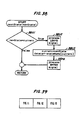
- the enter signal is generated for ringing state 208. Since the enter signal is generated internal to latter state, it is not illustrated in FIG. 2; but it is explained in detail with respect to FIG. 38.
- the generation of the enter signal causes triple 305 to be executed.
- the action definition of triple 305 applies the audible ringing "tone" or "indication" to handset l05.
- customer unit l02 leaves ringing state 208 by either going off-hook causing an off-hook signal 22l to be generated or by receiving a disconnect signal 222 from customer unit l03 via bus l00.
- the disconnect signal 222 from customer unit l03 indicates that unit l03 has gone on-hook. If customer unit l02 goes off-hook, the off-hook signal 22l is generated, and triple 308 is executed. Triple 308 informs customer unit l03 with a message containing answer signal 2l3 that customer unit l02 has answered. In addition, the state is changed to talking state 205 by the NEXTSTATE primitive.
- the leave signal When the state is changed, the leave signal is generated, and triple 306 is executed whose action definition causes the audible ringing "tone” or “indication” to be removed from handset l05. Since the leave signal is generated internal to ringing state 208, it is not illustrated in FIG. 2; but it is explained in detail with respect to FIG. 38.
- triple 307 is executed. This triple indicates the actions performed by customer unit l02 when calling customer unit l03 goes on-hook. However, no connection has been established at this point. If the massage is not from the calling customer unit, customer unit l02 simply continues in the ringing state 208. If the disconnect signal 222 was sent by customer unit l03, then the action definition of triple 307 is executed and the NEXTSTATE primitive moves the system back to idle state 20l.
- triple 308 causes the answer signal 2l3 to be transmitted to customer unit l03 and causes customer l02 to enter talking state 205.
- triple 320 of FIG. 4 is executed. The latter triple causes the necessary housekeeping to be performed in computer l04 to establish a voice path via bus l00 to customer unit l03.
- triple 322 is executed causing a disconnect signal 2l9 to be transmitted to customer unit l03 indicating that customer unit l02 has disconnected.
- the NEXTSTATE primitive is executed causing customer unit l02 to go to idle state 20l.
- the execution of the NEXTSTATE primitive generates a leave signal resulting in the execution of triple 32l.
- the action definition of triple 32l removes the voice connection to bus l00 for customer unit l02 by the execution of the DISENGAGE primitive.
- the illustrated scripts provide call forwarding (CF script), calling party identification (CPI script), and the activation and deactivation of the call forwarding (CFA script) feature.
- CF script call forwarding
- CPI script calling party identification
- CFA script activation and deactivation of the call forwarding
- the call forwarding feature functions by transferring calls intended for customer unit l02 to another customer unit previously identified by the customer entering data via terminals l06.
- the calling party identification feature displays on terminal l06 which customer unit is attempting to place a call to customer unit l02.
- the call forwarding feature has precedence over the calling party identification. Hence, if the call forwarding feature is active, the calling party identification feature does not display the identification of the calling customer unit since the calling party identification feature is not executed. If call forwarding is not active, then the calling party identification feature identifies all calls that have been placed to customer unit l02 even if the latter is not in the idle state.
- the CF script for the call forwarding feature consists of triples 50l and 502 as illustrated in FIG. 5 and demonstrates the interscript precedence mechanism using the STOP and CONTINUE primitives.
- Triple 50l can be executed in any of the states illustrated in FIG. 2.
- Triple 50l is actuated by an input signal designating that a "#" has been typed on terminal l06. If such an input signal is generated, then triple 50l's event definition sets the $CFNUMBER variable equal to the string of characters that the customer types after "#" on terminal l06.
- Triple 50l's action definition executes the STOP primitive which results in no further processing of the input signal by any other triples from any scripts in any states.
- the purpose of executing the STOP primitive here is to stop any further processing of the input signal rather than to control interscript precedence.
- triple 502 Assuming that triple 50l has been actuated and that the $CFNUMBER has been set equal to the number for the identified customer unit l03, an origin signal 223 received in any state causes triple 502 to be executed.
- the execution of triple 502 first results in the $SOURCE variable being set equal to the calling customer unit's number by the event definition.
- the action definition of triple 502 then checks to determine that the $SCFNUMBER variable has been set equal to a nonnull value and that this value is not equal to the calling customer unit's number. If these conditions are true, then the "then" statement of triple 502's action definition is executed resulting in the FORWARD, PRINT, and STOP primitives being executed.
- the FORWARD primitive transfers the value of the $SOURCE variable to the identified customer unit along with the origin signal 223 indicating that call origination is being attempted.
- the PRINT primitive prints a message out on terminal l06 indicating the time at which the call was transferred to the identified customer unit.
- the STOP primitive is executed which inhibits the execution of triples in the CPI and POT scripts that respond to the origin signal in the current state of customer unit l02.
- the execution of the STOP primitive allows the CF script to inhibit the normal operations that would occur upon an attempt being made to set up a call.
- the STOP primitive is part of the interscript control mechanism.
- a CONTINUE primitive is executed.
- the latter's execution results in control being passed to other triples of lower-precedence scripts.
- the origin signal 223 will be handled by the CPI and POT scripts.
- the action definition of triple 504 prints out an indication that a call has been received from the customer unit identified in the origin message and then executes the CONTINUE primitive to invoke the operation of the POT script to set up the call.
- the connection is set up as previously described with respect to FIGS. 3 and 4.
- the compiler is executed by computer l0l and is responsive to the scripts illustrated on FIGS. 3, 4, and 5, to compile these scripts prior to the transfer of the complied triple code to illustratively computer l04.
- the activation operation performed in computer l04 establishes the following precedence among the scripts: CFA, CPI, and CF with the CFA script having the highest precedence.
- the CFA, CPI and CF scripts could be compiled at a latter point in time and downloaded.
- a program in computer l04 is responsive to the compiled triples of these scripts to store these triples as logically illustrated in FIG. 6 for idle, ringing, and talking states, and to provide a method for executing these triples.
- the triples associated with the other states would be similarly stored.
- the triples are grouped by their event definitions for each state.
- indexing is provided that allows for execution of a triple in response to a signal that corresponds to a particular event definition when the present state corresponds to the state definition.
- origin signal 223, when received in the idle state 20l can sequentially activate triple 502 of the CF script, triple 504 of the CPI script, and triple 303 of the POT script.
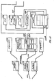
- the origin signal 223 transmitted from customer unit l03 to customer unit l02 is received by computer l04 via bus l00 by V_RCV process l002.
- the latter process then communicates the origin signal 223 to feature control process l000 via an operating system call.
- the execution of these processes is controlled by an operating system that controls the operation of computer l04.
- a hardware interrupt occurs causing the operating system to send an interrupt message to V_IN process l002.
- the latter process responds to the interrupt and determines that the customer has gone off-hook and then transmits the off-hook signal via an operating system call to feature control process l000.
- the execution of the operating system call to transfer the off-hook signal to feature control process l000 results in the operating system executing feature control process l000.
- feature control l000 Once feature control l000 is invoked, it first determines what signal it has received, determines the present state of the customer unit, and then executes the triples in that state whose event definition matches the received signal. To illustrate how this matching is accomplished, consider the transmission of an origin message 223 via bus l00 from customer unit l03 to customer unit l02. V_RCV process l00l receives this message and transfers the origin signal to finite state machine (FSM) l005 of feature control l000. FSM l005 is responsive to the origin signal to index into logical signal tables 60l through 606 that are associated with the idle state 20l. FSM l005 then identifies origin logical signal table 602 and has the triples identified by table 602 interpreted by interpreter l006. The manner in which the indexing is performed on actual physical tables, and the identification of the triples to be executed for a given state and signal are detailed with respect to FIGS. ll, l2 and l3.
- FSM finite state machine
- FSM l005 After identifying logical signal table 602, FSM l005 passes a pointer, which is stored in entry CF,502 of table 602, to interpreter l006 to identify the location of the compiled triple code to be executed.
- the action implemented by the identified triple code is defined by triple 502 as illustrated on FIG. 5.
- the first set results if $CFNUMBER variable contains a number and the calling customer unit is not the customer unit to which customer unit l02 is transferring its calls. If the conditions for the first set of operations are met, then the origin signal and the calling customer unit's number are transferred to the designated call forwarding customer unit by execution of the FORWARD primitive. Also, a notification message is printed on data terminal l06, and the STOP primitive is executed. The effect of the STOP primitive is to cause FSM l005 to cease processing triples in logical signal table 602.
- the second set of operations is performed when the conditional portion of the "if" statement of triple 502 is false, causing the "else” portion to be executed.
- the "else" portion of the "if” statement causes the CONTINUE primitive to be executed which results in FSM l005 executing the remaining triples in logical signal table 602.
- triple 504 of FIG. 5 which is pointed to by the CPI,504 entry.
- the execution of triple 504 results in a message being printed out on terminal l06 identifying the calling customer unit.
- the CONTINUE primitive is executed which results in the execution of triple 303 as identified by the POT,303 entry in table 602.
- triple 303 results in the identification number of the calling customer unit being saved in $ORIGINATOR and $OTHERPARTY and a message being transmitted to the calling customer unit indicating that the called customer unit is entering the ringing state 208.
- the NEXTSTATE primitive is executed, resulting in the leave signal being internally generated, the state being changed to the ringing state, and the enter signal being internally generated within feature control l000 by FSM l005.
- FSM l005 processes the leave and enter signals in a manner similar to the signals being received from another process such as V_RCV process l00l. Further details on the processing of the leave and enter signals is given with respect to FIG. 38 which illustrates the NEXTSTATE primitive.
- the leave signal relates to the idle state 20l in the present example. Since there are no entries in the logical signal table for the leave signal associated with the idle state, no action results from this signal in the present example.
- the enter signal which relates to the new state, i.e., ringing state 208, causes the compiled code pointed to by entry POT,305 of logical signal table 6l4 to be executed. This compiled code corresponds to triple 305 illustrated in FIG. 3.
- the action definition of triple 305 results in the audible ringing tone being applied to handset l05.
- the action definition causes the CONTINUE primitive to be executed; however, since there are no more triples to be executed in logical signal table 6l4, no other triples are executed in response to the enter signal.
- V_IN process l002 If, during the ringing state 208, handset l05 goes off-hook, this fact is detected by V_IN process l002 and an off-hook signal 22l is transmitted to FSM l005.
- the latter process identifies that it has received the off-hook signal and that it is in the ringing state and indexes into logical signal table 608.
- FSM l005 accesses the pointer stored in POT,308 and passes this pointer to interpreter l006 which executes the compiled code for triple 308 as illustrated in FIG. 3.
- the latter triple transmits the answer signal 2l3 to the calling customer unit by execution of the SEND primitive, and executes the NEXTSTATE primitive to change the state to the talking state 205.
- the execution of the NEXTSTATE primitive causes the leave signal to be generated for the ringing state and the enter signal to be generated for the talking state.
- FSM l005 is responsive to the leave signal to direct the interpreter l006 to execute the triple pointed to by entry POT,306 of logical signal table 6l5.
- the execution of the compiled code for triple 306 illustrated in FIG. 3 results in the ringing tone being removed from handset l05 of FIG. l.
- FSM l005 indexes into the logical signal tables 62l through 629 associated with the talking state and identifies the triple pointed to by the contents of the POT,320 entry for enter logical signal table 626.
- This pointer is passed to interpreter l006 which executes triple 320 of FIG. 4.
- the latter triple causes a voice communication path to be set up between the calling customer unit and customer unit l02 by execution of the ENGAGE primitive.
- V_IN l002 If, during the talking state 205, customer unit l02 goes on-hook, this fact is detected by V_IN l002 process and an on-hook signal is transmitted to FSM l005.
- the latter is responsive to the on-hook signal to identify and pass the pointer to interpreter l006 contained in POT,322 of logical signal table 628.
- the latter pointer points to the compiled code for triple 322 as illustrated in FIG. 4. Execution of this compiled code results in the execution of the SEND primitive which transmits the disconnect signal 2l9 to the calling customer unit and the execution of the NEXTSTATE primitive to change the state to idle 20l.
- the execution of the NEXTSTATE primitive causes a leave signal to be generated for the talking state 205 and an enter signal to be generated for the idle state 20l.
- FSM l005 is responsive to the leave signal to identify and pass the pointer to interpreter l006 contained in logical signal table 627.
- the latter pointer points to the compiled code for triple 32l, as illustrated on FIG. 4. Execution of the latter compiled code results in the voice communication path from customer unit l02 to the calling party being broken. Since there is no enter logical signal table associated with the idle state, the generation of the enter signal has no effect.
- Tonegen process l004 is responsive to the fact that it is 5:00 p.m. has passed to transmit a time signal to FSM l005.
- the latter process is responsive to the time signal to identify time logical signal table 625 associated with the talking state.
- FSM l005 first passes the pointer pointing to the compiled code of triple 506 to interpreter l006; and after interpreter l006 has finished processing triple 506, FSM l005 passes the pointer from logical signal table 625 for triple 507 to interpreter l006 for execution.
- the first action of the compiled code for triple 506 is to check whether or not the time is equal to 8:00 a.m., verifying that the event time (8:00) has occurred. Since, in our present example, the time is 5:00 p.m., the event does not match and the action definition of triple 506 is not executed.
- Interpreter l006 returns control to FSM l005 which then passes the pointer contained in CFA,507 entry of logical signal table 625 that points to triple 507 as illustrated in FIG. 5 to interpreter l006. The latter is responsive to this pointer to start execution of the compiled code for triple 507.
- the first part of the compiled code for triple 507 verifies whether or not the event matches the specified time (l7:00) event before proceeding to execute the action definition portion of the triple. Since the time is 5:00 p.m., or l7:00 on a 24-hour time base, and assuming that the day is Monday through Friday, the DEACTIVATE primitive and the PRINT primitive of triple 507 are executed.
- the DEACTIVATE primitive causes a deactivate signal to be transmitted to FSM l005 indicating that the CF script is to be deactivated. No actual deactivation takes place at this point in time.
- FSM l005 When FSM l005 receives the deactivate signal, it processes through all of the states to remove all triples that are part of CF script 500, as illustrated on FIG. 5. This process is described in greater detail with respect to FIGS. 23 through 28.
- the CF script 500 does not have a triple whose event definition is responsive to the deactivate signal so the triples can simply be removed by FSM l005, thereby completing the actual deactivation of the CF script.
- the logical signal tables of the idle, ringing, and talking states contain the pointers to triples as illustrated in FIG. 7. For example, in the idle state, since the reference to the CF triples has been removed, the calling party identification triple is now the first triple executed in logical signal table 702 when an origin signal is received in the idle state.
- the inter-feature precedence could be changed by altering the manner in which the references to the triples are stored in the logical signal tables of FIG. 6.
- the CPI triples would be placed on top of the call forwarding triples in the logical signal tables.
- origin logical signal table 602 the order would be CPI,504; CF,502; and POT,303.
- the entries in origin logical signal table 609 and origin logical signal table 62l would be changed.
- the compiled code is downloaded to the computer l04 where it is stored into memory l08 under control of processor l07 executing the program illustrated in FIG. 9.
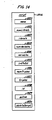
- the format of the downloaded compiled code is illustrated in FIG. 8.
- Location 80l specifies the total number of bytes in the downloaded compiled script, and the number of distinct literals in the script is specified by location 802.
- the literal strings are downloaded in block 803 with each literal being terminated by a null character.
- the number of distinct variables in the script is specified by location 804, and the variable strings representing the variable names are downloaded in block 805.
- the number of triples in the compiled script is specified by location 806 while the actual compiled triples are located in block 807.
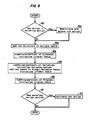
- Block 90l determines whether the new script is already present in memory l08. If the script is present, the old script is deactivated and deleted before block 904 is executed. The latter block adds a new structure into the SCRIPTS table to make room for the new script. Blocks 906 and 908 update the literal and variable tables such as literal table 2204, local variable table 220l, and global variable table 2202, respectively. Block 9l0 performs the necessary initialization with respect to a triples table such as 2204. Decision block 9ll determines whether the existing script had been active when the new script was downloaded, and if it was, the new script is activated by passing control to block 9l2.
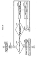
- FIGS. ll, l2, and l3 The data structures utilized by feature control process l000 in identifying which triple is to be executed in response to a given signal are illustrated in FIGS. ll, l2, and l3.
- the latter figures illustrate a detailed implementation of the logical signal tables represented in FIGS. 6 and 7.
- FSM l005 illustrated in FIG. l0 receives a signal from one of the processes l00l through l004, FSM l005 first utilizes the current state index stored in location ll0l and the state pointer stored in ll02 to determine a location in state table ll04 via path ll03.
- the value stored at a location in state table ll04 is a pointer that indirectly points to a location in FSMSignal table lll0 via path ll05, FSMSignalPTR location ll07, and path ll08.
- State table ll04 contains one indirect pointer for each of the possible customer units' states.
- each FSMSignalPTR pointer in ll06 through ll07 and ll20 for each of the possible states.
- Each of the FSMSignal tables ll09 through lll0 and ll2l is associated with one of the possible states.
- Each entry in an FSMSignal table is associated with an event definition for a signal that can occur in the state associated with that table. For example, once FSM l005 indexes to FSMSignal table lll0, FSM l005 then utilizes the signal number that identifies the signal being processed to index to the correct location within the latter table.
- FSMSignal table lll0 points indirectly to ProgramID table lll6 via path llll, triple list lll3, and path lll4.
- Triple lists such as lll3 are also referred to as FSMSignal locations.
- FSMSignal locations For each of the possible signals which any of the states represented by FSMSignal tables ll09 through lll0 and ll2l can respond, there exists for each signal an FSMSignal location lll2 through lll3.
- ProgramID table lll6 is also illustrated in FIG. l2.
- a ProgramID table such as lll6 contains references to all of the triples that can respond to the signal that FSM l005 is presently processing and contains references to all the triples contained in the corresponding logical table of FIGS. 6 and 7.
- FSM l005 In order for FSM l005 to fully process the signal, it is necessary to execute each triple associated with an entry in a table such as ProgramID table lll6 or until the STOP primitive is executed by one of the triples. In order to process all the triples represented by the entries in table lll6, FSM l005 maintains a current index variable and starts to process these entries with the most recently activated triple. Each entry in table lll6 consists of an index into a script table, such as l20l, and an index into a triple table such as l208. Script table l20l is pointed to via path l202 which is an index from the bottom of table l20l pointed to by the SCRIPTS variable. The identified location in script table l20l points to script list l206 via path l203.
- FSM l005 stores the pointer identified in script table l20l in the CURRENTSCRIPT variable.
- Script lists l205 through l207 contain all the information concerning the triples for a particular script that is common to the triples for that script.
- the memory location designated as name l220 contains the name of the script.
- the location designated as numLiterals l22l contains the number of distinct literals that are used by all the triples in this script.
- the area designated as literals l222 comprises two segments.
- the first segment is a table of pointers that are indexed by the literal ID field of a literal argument instruction which designates the actual literal string contained in the second segment of area l222.
- This second segment comprises the literal strings.
- the area designated numVariables l223 contains the number of distinct variables used by all the triples in the script.
- the area designated variables l224 comprises the variable names as string variables that are indexed to by the ID field of a variable argument instruction. Variables l224 is used during the initial downloading of the system.
- Area intToExt l225 is a table of pointers that is indexed by the variable ID field of a variable argument instruction of triple and contains indexes to a global table of variable values.
- the area designated numTriples l226 defines the total number of triples contained in triple array l208 pointed to by variable l227.
- Variable id l228 is used to store the index used to index into script array l20l.
- the variable l229 designates whether the script is currently active or not.
- the variable designated deleteScript l230 is used when a script is to be totally removed from memory.
- Triples l227 in script list l206 of FIG. l2 or FIG. l4 contains a pointer to triple table l208.
- the latter table contains pointers which indirectly point to the compiled code for the triples of the script.
- Triple table l208 is indexed into using the triple field from ProgramID table lll6 via path l204.
- the location indexed by path l204 into triple table l208 points to triple l2l0 that comprises a series of memory locations that, in turn, point to various pieces of information within the actual coded implementation of the triple.
- There is one coded implementation of a triple for each entry in triple table l208 and a corresponding triple such as triples l209 through l2ll.
- interpreter l006 illustrated in FIG. l0 once again returns control to FSM l005.
- the latter indexes to the next location in ProgramID table lll6, indexes through a path similar to what was previously described, until the new code for the next triple is identified by one of the triples l209 through l2ll, and then, FSM l005 once again passes control to interpreter l006. This process continues until all of the triples in ProgramID table lll6 have been executed or until one of the triples executes a STOP primitive.
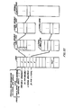
- the compiled code format of a triple is illustrated in FIG. l5 and is encoded using numerical codes (ASCII).
- Location l500 defines the number of bytes in the compiled code.
- the number of states specified in the state definition of the triple i.e., the number of states to which the triple applies
- location l50l The number of states specified in the state definition of the triple (i.e., the number of states to which the triple applies) is stored in location l50l and the numerical IDs of these states are located in location l503.
- the ID of the named event is stored in location l504.
- the information stored in l50l through l504 is utilized during the activation of a script.
- the instruction portion or action of the compiled code is contained in locations l505 and l506.
- Area l505 normally comprises two distinct portions. If there are no event parameters specified in the event definition, then there is just the second portion
- the first portion of area l505 is utilized to recover values that are being passed into the compiled triple code by the signal occurrence and to make the determination whether or not the event definition of the triple has been fully satisfied and thus whether or not the subsequent portion should be executed.
- the second portion of area l505 contains primitives and instructions.
- Location l506 contains the HALT primitive which causes interpreter l006 to return control to FSM l005 if a STOP or CONTINUE has not been encountered previously in the execution of area l505.
- the primitives are subroutine calls to C++ functions to perform the actions indicated.
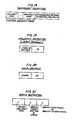
- FIGS. l7 and l8 illustrate the general sequence of the codes in area l505 .
- FIG. l7 illustrates the assignment instruction where the instruction comes first followed by the internal identification code of the variable to receive the assignment.
- FIG. l8 illustrates the SENDMESSAGE instruction which can have an optional number of parameters to be transmitted indicated in the second field of the instruction.
- the argument codes fall into the classes of literals, variables, branch-to-address arguments, or signal arguments.
- FIGS. l9 and 20 illustrate the format of these instructions for the literal or variable and the signal argument, respectively.
- interpreter l006 When one of these arguments is encountered by interpreter l006, it takes the following internal identification code, labeled as ID, obtains a pointer to the actual value using the ID as an index into a table, and pushes this pointer onto the interpreter stack.
- the instruction or primitive using that argument is executed, it pops the stack to obtain the pointer and utilizes this pointer to pass the actual value.
- the event parameters of a triple can transfer information into the compiled triple at the time the triple is executed. This information can consist of a retrieved value for a variable or can consist of a plurality of values, e.g., "input" event.
- FSM l005 stores any values that must be passed into the event parameter code in the SIGNAL_ARG array.
- the first instructions of the compiled code for a triple retrieve these values. For an event definition such as "origin ($SOURCE)", the value recovery code simply accesses the first location of the SIGNAL_ARG array and obtains the value stored there and sets the $SOURCE variable equal to the retrieved value.
- the input, rcvmessage, and reply events also can have a variable number of variable arguments whose values must be obtained from the SIGNAL_ARG array by positional correspondence at the time the triple is executed and stored in the proper variable locations. After the values have been recovered, the remainder of the triple code is executed.
- FIG. 2l The format of a branch instruction is illustrated in FIG. 2l.In the case of a conditional branch, the interpreter pops from the stack the test value which determines a branch or no branch. Tables I, II, and III give the decimal numerical codes for the event, state, and instruction codes, respectively.
- FIG. 22 illustrates the manner in which the literal and variable codes of a triple are utilized to gain access to the variable and literal information, respectively.
- the local variable table 220l, literal table 2204 also called literal l225 in FIG. l4, and list of literals 2205 are maintained in the associated script list, such as script list l206 of FIG. l4. List of literals 2205 is part of the compiled script.
- the variable code is utilized to access the local variable table 220l also called intToExt table, such as l225, in FIG. l4 from which an index is obtained into the global variable table 2202.
- the global variable table 2202 is common to all scripts within a given customer unit.
- variable table 2202 From global variable table 2202, a pointer is obtained to the variable values 2203 which contains the actual character string value of the variable. Similarly, the literal code is utilized to access literal table 2204 (l222) from which a pointer is obtained to literal value 2205. All literals and variables in their associated lists are terminated with a null character to designate the end of each respective item of information.
- code within the prompt-user process l003 is responsive to data being received from the computer l0l to be stored in the tables illustrated in FIGS. ll, l2 and l3.
- FIGS. 23 and 24 illustrate in flowchart form, a program for implementing FSM l005.
- FIGS. 23 and 24 detail the logical flow of the program written in C++ whick is described in detail in the book entitled, The C ++ Programming Language , by B. Stroustrup.
- Blocks 23l3 and 23l4 perform the deactivation of a script (i.e., the modification of tables and pointers in FIGS. ll, l2, and l3) when a deactivate signal is received, and block 23l5 performs the activation of a script when an activate signal is received.
- a script i.e., the modification of tables and pointers in FIGS. ll, l2, and l3
- block 23l5 performs the activation of a script when an activate signal is received.
- Block 230l first initializes certain variables internal to FSM l005.
- the $THIS variable is set equal to the calling number of the customer unit and the i_arg variable is set equal to an index into a table of pointers that identify the parameters being passed with different operating system messages.
- the parameters comprise any string information associated with the signal.
- Block 2303 sets the MSGTYPE variable equal to the message type within the message by utilizing the ip pointer to point to the message type stored in the area designated by the operating system.
- Block 2304 utilizes the MSGTYPE index to index into the signal "#" table that contains numerical identification for each signal type. These decimal values are defined in Table IV.
- decision block 2305 determines whether or not the signal is the activate signal or not. If the signal is the activate signal, then block 23l5 is executed. The details of block 23l5 are given with respect to FIGS. 29, 30, and 3l.
- Block 2306 is utilized to access into the table FCSIGNALNAME with the SIG variable in order to identify the event corresponding to the present signal being processed and to store the name string for the event in the $EVENT variable.
- Blocks 2307 and 2308 access the parameters of the operating system message and store these parameters in an array called ARG.
- Block 2309a implements the paths shown in FIGS. ll and l2 to determine which FSMSIGNAL structure to utilize such as FSMSIGNAL lll3.
- the latter block implements the logical paths from variables ll0l and ll02 through state table ll04, an FSMSIGNALPTR variable, such as in ll07, and FSMSIGNAL table, such as lll0.
- Block 2309b sets the current index to zero. The current index is used to index into a ProgramID table such as lll6.
- block 2309b sets the return code equal to CONTINUE. During the interpretation of the compiled code, the code for a given triple may change the return code to a STOP.
- block 2309a sets the THISSIGNAL variable equal to the SIGNAL variable.
- this entry points to a ProgramID table via a triple list, such as in lll3.
- Blocks 23l0 and 23ll then proceed to execute the compiled code for all of the triples identified in the designated ProgramID table.
- the designated ProgramID contains pointers which identify for the current state of the customer unit all of the triples that can respond to the signal presently being processed.
- Block 23lla is utilized to identify a script structure such as l206 of FIG. l2 via the script portion of an entry in the ProgramID table lll6 via a script table such as l20l.
- the entry in the script table identified as illustrated by path l202 determines the script containing the triple presently being processed.
- the identified entry in the script table is stored in the CURRENTSCRIPT variable.
- Block 23llb then identifies the compiled triple code l2l0 to be executed via illustratively the path shown on FIGS. l2 and l3 of path l2l2, path l204, triple table l208, and path l2l5.
- the variable TP is set equal to the identified triple such as l2l0.
- Block 23llc then causes the execution of the function "EXECUTE" which actuates interpreter l006 illustrated in greater detail in FIGS. 34, 35, 36, and 37.
- Block 23llc passes to the interpreter the TP variable which points via the triple l2l0 to the compiled triple code to be executed.
- the interpreter returns the value of the returned code which is either a STOP or CONTINUE.
- Block 23lld then increments the current index so that compiled code for the next triple in the designated ProgramID table lll6 can be executed.
- decision block 23l0 passes control to block 23l2 if any of the following conditions are true.
- the second condition that is checked is whether the current index is greater than the number of entries in the designated ProgramID table lll6.
- the final condition checked is whether or not the triple just interpreted by block 23llc had executed the PURGESCRIPTID routine. Execution of the latter routine would not only have removed the executing triple from the ProgramID table, but possibly other unexecuted triples in the same script.
- this final condition is met if initially there are no triples that can respond to the current signal in the current state. If the removal of the unexecuted triples resulted in no other triples left in the designated ProgramID table, then the ProgramID table lll6 is removed and the triple list pointer of lll3 is set to NULL. If any of the three previous conditions are met, block 23l2 is then executed setting the initial conditions for indexing into the ARG table to the correct value for subsequent execution by block 2308.
- Blocks 23l3 and 23l4 detail the handling of a deactivate signal.
- the deactivate signal can have a corresponding deactivate event within the script to be deactivated, and a script, by utilizing a deactivate event, can postpone the physical deactivation or purging of the script to a later point in time.
- This capability is given to scripts whose work cannot be arbitarily terminated but must go to completion.
- Such a script is illustrated in FIGS. 8 and 9.
- a script defers its deactivation to a later point in time by executing a STOP primitive within the script's triple that responds to the deactivate signal.
- Decision block 23l3 detects execution of the STOP primitive and does not execute block 23l4 which performs the purging of the script.
- Block 23l4 performs the purging of a script by removing references to all triples contained within the script in all ProgramID tables.
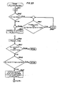
- Block 23l4 of FIG. 24 is shown in greater detail in FIG. 25.
- the PURGESCRIPTID procedure functions by cycling through each state and each signal within that state to remove all of the triples associated with the script being deleted from the ProgramID table corresponding to that signal for that state. It utilizes the DELSCRIPT function referenced in block 2505 to remove these triples.
- the variables i and j are used to index into the states and signals, respectively. Initially, i is set equal to zero by block 250l. All of the states are then checked to see if there are any triples associated with the script being deleted as designated by the contents of the THISSCRIPT argument or parameter.
- Decision block 2502 determines when all states have been checked by comparing i to the total number of states as contained in the variable FC_STATES. As long as i is less than the total number of states, blocks 2503 through 2507 are executed. For each iteration through blocks 2503 through 2507, block 2503 sets the j variable equal to zero. Decision block 2504 controls the execution of the DELSCRIPT function until all the signals have been deleted.
- the DELSCRIPT function is passed a pointer identifying the ProgramID table from which it is to delete all triples associated with the script being deactivated. Then DELSCRIPT function then cycles through all of the entries of the designated ProgramID array eliminating the triples associated with the script being deactivated.
- the i variable is stepping through the state table ll04 of FIG. ll. For each entry in table ll04, an FSM signal table, such as lll0 is identified. The j variable then steps through each entry in the identified FSM signal table with each entry identifying a ProgramID table via a triple list/FSM signal variable such as lll3.
- the DELSCRIPT function of block 2505 of FIG. 25 is illustrated in greater detail in flowchart form in FIGS. 26, 27, and 28.
- the triples associated with a script are deleted in two stages. The first stage is for blocks 2604 through 2609 to determine the new number of triples identified in the ProgramID array lll6 which is stored in GOODTRIPLES and the new value for the current index variable which is stored in NEWINDEX.
- the actual removal of the triples associated with the present script and signal is performed by blocks 26ll through 26l9.
- the procedure is to create a temporary ProgramID table, transfer all of the triples to be saved from the old table and then make the temporary table the new ProgramID and identify it in a TRIPLELIST variable, such as in lll3.
- the NEWINDEX variable is set equal to the CURRENTINDEX variable.
- the CURRENTINDEX variable is equal to the index of the triple presently being processed in blocks 23l0 through 23ll of FIG. 24.
- the variable GOODTRIPLES is initialized to zero. Since blocks 2503 through 2507 of FIG. 25 assume that every signal has a corresponding ProgramID table in each state, it is necessary to verify whether or not the particular signal being processed, indeed, does have a corresponding ProgramID table for a particular state. This determination is performed by decision block 2602. As illustrated in FIG. ll, an FSMSIGNAL table has pointers to a series of triple lists lll2 through lll3.
- each FSMSIGNAL table There is one entry for every possible signal in each FSMSIGNAL table and there is a corresponding FSMSIGNAL structure/triple list for each entry. If there is not a triple responsive to a particular signal for a given state, the triple list for that signal contains a null value. If the triple list identified by a particular entry in the present FSMSIGNAL table that the PURGESCRIPTID function is processing contains a null value, then decision block 2602 returns control to the PURGESCRIPT function. If the triple list does not contain a null value, this means that the signal has a set of corresponding triples in this state and control is transferred to block 2603.
- Decision block 2604 determines whether or not the number of triples identified in the present ProgramID is greater than the maximum number.
- the maximum number of triples in a ProgramID is stored in location k such as in lll6, as illustrated in FIG. l2. If i is less than the maximum number of triples, then decision block 2605 is executed to determine whether the entry in the ProgramID block is related to the script that is being deleted. If the script index is different than the script presently being processed, which is identified by an entry in the THISSCRIPT variable, block 2609 is executed which increments the GOODTRIPLES variable by one. If the script for the triple entry presently being pointed to by i matches the THISSCRIPT variable, then block 2606 is executed which marks the entry in the ProgramID table pointed to by the i variable as invalid for later processing by blocks 26ll through 26l9.
- Control is then passed to decision block 2607.
- the latter decision block determines whether or not the triple that is to be removed is referenced lower in the ProgramID table then the current triple which is being executed and which had actually activated the DELSCRIPT function. If the ProgramID table presently being processed is that of the triple that caused the DELSCRIPT function to be executed and i is less than the current index which points to the triple being executed, then block 2608 is executed which causes the NEWINDEX variable to be decremented by one. This is done since the NEWINDEX variable was set equal to the CURRENTINDEX variable in block 260l. The contents of the NEWINDEX variable are used in block 26l9 to adjust the CURRENTINDEX variable so that execution can continue from the ProgramID table after the present triple has finished being interpreted.
- decision block 26l0 is executed to determine if there are any triples left or if all triples in the ProgramID array were associated with the script that is being purged. If the latter condition is true, block 2620 is executed and the triple list is set equal to null value indicating that, for this particular state, there are no triples responsive to this particular signal. Then, the CURRENTINDEX is set equal to zero also so that no attempt is made later to execute another triple from this ProgramID table when control is returned to the FSM l005.
- Block 26ll sets a pointer TMPLIST equal to a new table having its number of entries equal to the number contained in the GOODTRIPLES variable. Blocks 26l3 through 26l7 then index through the ProgramID table looking for the entries that are not marked invalid. Any entry that is not marked invalid is transferred to the new array table by blocks 26l5 and 26l6 which insert the script and triple identifications, respectively. After all of the entries in the ProgramID have been checked, control is transferred to 26l8 which sets the triple list pointer from the FSMSIGNAL table equal to the TMPLIST variable.
- Block 26l9 sets the number of triples as stored in the ProgramID table in the k location equal to the number contained in the GOODTRIPLES variable. And sets the CURRENTINOEX equal to the NEWINDEX variable.
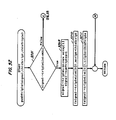
- Blocks 290l through 2905 illustrate the details of the ACTIVATE primitive. The purpose of blocks 290l through 2905 is to determine the numerical code for the script that is to be activated and then to send an operating system message containing this numerical code as a parameter to process control l000. When process control l000 receives this message, it invokes FSM l005.
- control is transferred from decision block 2305 to block 2906.
- the latter block initializes i to the script code by obtaining the latter from the list of parameters in the message passed by the operating system.
- Decision block 2907 determines that the script code is valid; and, if it is, turns over control to decision block 2908.
- the latter decision blocks determine whether the present script has already been marked as active in the script structure or location such as l206 by first obtaining a pointer from script table l20l through utilizing the variable i as an index into the latter table.
- Block 2908 checks the value of the ACTIVE variable l229 of l206. If the present script is marked inactive, then block 2909 is executed.
- the purpose of the code 2909 through 29ll and blocks 29l7 through 2923 is to insert into the ProgramID tables references to the triples of the script being activated. These references are only inserted into ProgramID tables that correspond to the state and the signal as designated in the state definition and event definition of each triple of the script being activated.
- the address of the script table l20l is known and the relationship of the scripts by numerical code can be used to index into table l20l.
- the information in the latter table is utilized in order to identify the triples of a script by processing, as an example, along path l203, script l206, paths l2l2 and l204, triple table l208, path l2l5, and triple l2l0.
- the code shown in block 29l8 can utilize the coded state and signal information within the compiled triple code itself to determine what ProgramID tables must receive a reference to the triple.
- the THIS pointer is set equal to the contents of the script table l20l indexed by the variable i and is then used to point into the variables for the script l206.
- the THIS pointer is also used to set the ACTIVE variable, such as l229, to TRUE.
- the variable t is set equal to one less than the number contained in the NUMTRIPLES variable stored in the script list.
- the THISSCRIPT variable is set equal to the contents of the variable i. The reason for setting t in this manner is that the first triple of a script has to have the highest priority, hence, it has to be the last triple pushed onto any particular ProgramID table.
- Pointer TP points to a triple, such as l2l0.
- the triple contains pointers that identify the number of states and the signal that the triple associated with the triple list has in its state and event definitions. This information is used by decision blocks 29l7 and 29l9 and in block 29l8, to determine how many states are present in the compiled code.
- the program illustrated in blocks 29l7 through 2923 takes the compiled code for each triple and inserts references to that code by the utilization of the PUSHTRIPLE function of block 2920 into the ProgramID tables indicated by the coded states and the signal of the compiled triple itself.
- the variable i is used to index into the states identified in triple's state definition. Further details of this process are given with respect to FIGS. 32 and 33 which illustrates the PUSHTRIPLE function.
- block 2923 is executed and t is decremented by one, and execution is passed to blocks 29l0 and 29ll.
- This process results in the triple table, such as l208, being sequentially indexed through and the compiled triples indirectly pointed to by the locations of the triple table being properly identified in the required ProgramID tables.
- decision block 29l0 passes control to block 29l2.
- Block 29l2 executes code similar to that illustrated by blocks 2306 through 23l4 of FIGS. 23 and 24. This allows the activate signal to be processed by any triples of the recently activated script which contain the activate event.
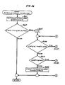
- This PUSHTRIPLE function is illustrated in greater detail in FIGS. 32, and 33.
- the first condition is that the ProgramID table into which the triple is to be placed already exists, and the second condition is that the ProgramID table does not exist.
- Decision block 320l makes the determination of which condition exists by checking to see if the designated triple list location, such as in lll3, contains a null value indicating that the ProgramID table does not exist. If the ProgramID table does exist, then block 3202 is executed which creates a new array and sets a TMPLIST pointer to identify the location of the new array. Block 3203 is then executed which inserts the script and triple identification into the first entry of the new array, thus, identifying the compiled triple code in this new array. Block 3204 sets up the initial value of the variable i.
- Blocks 3205 through 3207 copy the script and triple identification information from the original ProgramID table into the new array table.
- Block 3206 copies the script identification information
- block 3207 copies the triple identification information.
- block 3208 is executed which inserts the pointer contained in TMPLIST pointer into the triple list location, such as in lll3, thus making the new array the ProgramID table which is pointed to by an entry in the FSMSIGNAL table, such as lll0.
- block 3208 also inserts the number of triples that are identified by the new ProgramID table into the location designated as k in the ProgramID table.
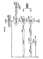
- FIGS. 34, 35, 36, and 37 illustrate the flowchart for interpreter l006 of FIG. l0.
- interpreter l006 sets the RETURNCODE variable equal to UNDEFINED and obtains the location of the first instruction to be interpreted by executing block 340l.
- interpreter l006 continually executes blocks 3402 and 3405 so on through 3434 until a HALT, STOP, or CONTINUE instruction is encountered.
- RETURNCODE is set to STOP or CONTINUE (the latter for both HALT and CONTINUE instructions) blocks 3403 and 3404 are executed and control is returned to FSM l005 along with the RETURNCODE value.
- the HALT, STOP, or CONTINUE instructions terminate the execution of the coded instructions by resetting the RETURNCODE variable and cause control to be returned to FSM l005 of FIG. l0.
- decision block 3405 is executed to determine whether an unconditional branch instruction is the next instruction to be executed. If the unconditional branch instruction is present, the interpreter stack is popped, and the popped value is stored into the PC variable resulting in the interpreter branching to a new position in the code determined by the popped value. The popped address was originally put on the stack by a branch argument instruction being detected by decision block 34l7. Then block 34l8 obtains the jump index as was illustrated in FIG. 2l, and adds this index to the location of the first instruction address of the code and pushes the result onto the stack.
- conditional branch instruction The execution of a conditional branch instruction is shown in blocks 3406 through 34l0. Before the execution of a conditional branch, a branch argument instruction would have been executed placing onto the stack an index to where the branch is to occur. Once a conditional branch instruction is detected by decision block 3406, control is transferred to block 3407 which stores the popped branch address index into a local variable designated as "P". Next, decision block 3408 pops from the stack the address of the TEMP variable which contains the result of a comparison and/or a logical operation that had been placed on the stack by execution of a compare instruction and/or a logical operator instruction as illustrated by blocks 34l9 and 3420 and 3425, 3426, 3427, and 3428.
- block 3409 is executed causing the branch to occur to the designated place in the code in a manner similar to that performed by block 3438. If the result of the compare and/or logical operation instruction was false (zero), then block 34l0 is executed and the next instruction of the compiled code is executed.
- decision block 34ll transfers control to block 34l2.
- the latter block first obtains the literal ID field from the instruction whose format is illustrated in FIG. l9.
- the literal ID is utilized to access a literal table containing pointers to a list of literal strings both of which are contained in the script list, such as script list l206 of FIG. l2. Once the pointer is obtained, it is pushed onto the interpreter stack.
- decision block 34l3 transfers control to block 34l4.
- Block 34l4 functions similarly to 34l2 with the exception that the ID field is utilized to index into a local variable table to obtain a pointer to the global variable table. The latter pointer into the global variable table is pushed onto the stack by block 34l4.
- blocks 34l5 and 34l6 function similarly to blocks 34ll and 34l2 in obtaining a pointer to the signal argument from a list of signal arguments maintained on a global basis.
- Blocks 34l9 and 3420 function to implement the various compare operations by first popping the two values to be compared from the stack and then storing the result of this comparison into a temporary variable. A pointer to this temporary variable is then pushed onto the stack by block 3420. Functions are provided for comparisons based on equal, not equal, greater than, less than, greater than/equal, and less than/equal. Note, that the interpreter may use a number of temporary variables which are freed when the interpreter executes block 3403.
- blocks 342l and 3422 function to perform the arithmetic operations of addition, subtraction, multiplication, and division.
- Blocks 3423 and 3424 function similarly to the arithmetic instructions except that the unary negation function is performed on only one variable.
- a logical opcode instruction as illustrated by blocks 3425 and 3426 is handled in a manner similar to that of the arithmetic instructions by blocks 342l and 3422.
- the NOT instruction is handled in a manner similar to the NEGATE instruction and is illustrated in blocks 3427 and 3428.
- ASSIGN ASSIGN primitive format
- block 3430 accesses the second field of the instruction to obtain the ID of the variable in the compiled code to set that variable equal to the top value on the stack.
- the SENDMESSAGE format is illustrated in FIG. l8.
- Block 3430 accesses the second field of the instruction illustrated in FIG. l8 to obtain the number of optional parameters to be passed in addition to the two parameters always implied by this instruction. Block 3430 uses this number of optional parameters to determine how many additional arguments to pop from the stack.
- HALT and CONTINUE primitives are implemented by blocks 343l and 3432. Once the HALT or CONTINUE is detected, control is passed to block 3432 which sets the RETURNCODE equal to CONTINUE. Similarly, when the STOP instruction is detected by decision block 3433, control is passed to 3434 which sets the RETURNCODE equal to stop.
- the NEXTSTATE primitive is illustrated in greater detail in flowchart form, in FIG. 38.
- block 380l Upon invoking the NEXTSTATE primitive, block 380l first verifies that the state is being modified and, if it is, block 3802 is executed. The latter block sets the $EVENT variable equal to the string "leave” and executes code similar to that illustrated in blocks 2309 through 23l2 of FIGS. 23 and 24. This results in the leave signal being processed in the normal manner.
- block 3803 is executed to change the $STATE variable equal to the string representation for the numerical state code contained in the newState argument and to change the CURRENT variable ll0l to index the entry for the new state in state table ll04.
- block 3804 is executed which causes the $EVENT variable to be set equal to the string "enter” and code similar to that illustrated in blocks 2309 through 23l2 of FIGS. 23 and 24 is executed resulting in the enter signal being processed for the new state.
- the PODS of FIGS. 40 and 4l illustrates in greater detail, the manner in which a script controls its own deactivation.
- the PODS script illustrates the provision of data services for the system illustrated in FIG. l.
- the POT, PODS, CPI, CFA, and CF scripts are compiled and downloaded, they are inserted into the logical signal tables illustrated in FIG. 7 such that a logical signal table containing a triple for each script would have a CF triple on the top, followed by a CFA triple, a CPI triple, a PODS triple, and finally, a POT triple.
- triple 400l is executed in response to an activate signal which results in the $DATA and $DEACTIVATE variables being set equal to false.
- the $DATA variable indicates whether or not a data call is presently in progress; and the $DEACTIVATE variable indicates whether or not the script is to be purged when the idle state is entered.
- the purpose of a data call is to allow a customer to transmit a message that consists of a plurality of packets from the customer's data terminal to another customer's data terminal.
- this script such that the transfer was from a customer unit's computer to another customer unit's computer. Once the customer unit has established the data call to the other customer's data terminal, this data call remains operational until the customer disconnects the data call by inputing the word "disconnect".
- the customer During the setup of a voice call, the customer would go off-hook in the idle state and would be placed in the dialing state. While in the dialing state for a voice call, the customer would enter a sequence of digits and this would result in only a voice path being set up.
- the system distinguishes between a data call and a voice call by the fact that a data call receives the digits designating the called party during the idle state, whereas the voice call receives digits during the dialing state.
- the called party distinguishes between the origination of a data call and a voice call by the fact that a SENDMESSAGE is utilized to send the origin string in a message for a data call whereas the SEND primitive is used to send the origin message for a voice call.
- customer unit l02 leaves by the occurrence of the busy signal, input signal, or the receipt of a ringing message which results in the entry of the idle state, idle state, or audible state, respectively.
- Triples 40l7 and 40l3 illustrate the action definitions performed upon the occurrence of the busy or input signals, respectively.
- Triple 3ll as illustrated in FIG. 3, defines action taken upon receipt of the ringing message signal.
- triple 40l6 Upon entry into the audible state, triple 40l6 is executed resulting in a message being printed out on terminal l06 indicating that the other party has been alerted. While in the audible state, the customer unit can transfer to the idle state either by the occurrence of the input signal with the string "disconnect", or the occurrence of the busy signal from the called customer unit resulting in the execution of triples 40l2 and 40l7, respectively. When the called customer unit accepts the data call, the latter unit transmits a message to the calling customer unit utilizing the SEND primitive which sends an answer message. In response to the event of the answer message being received by the calling unit, triple 3l6 of FIG. 3 is executed resulting in customer unit l02 being transferred to the talking state.
- triple 40l0 Upon entering the talking state, triple 40l0 is executed resulting in a message being printed out that a connection has been made to the identified called customer unit, and since there is a CONTINUE primitive ending the action definition of triple 40l0, control is passed to triple 320 of the POT script as illustrated in FIG. 4.
- the execution of triple 320 causes a voice path to be set up in addition to the data path between the calling and called customer units.
- the talking state can be exited from by the execution of either triple 40ll or 40l2. Both of these triples transfer the calling customer unit from the talking state to the idle state.
- the voice path is removed by triple 32l as illustrated in FIG. 4 which is responsive to the leave event in the talking state to execute the DISENGAGE primitive.
- triple 4006 is executed assuming the called customer unit is in the idle state otherwise, triple 4005 is executed and a busy signal is sent back to the calling customer unit.
- the action definition of triple 4006 utilizes the SEND primitive to transmit the ringing signal back to the calling customer unit indicating that the called customer unit is entering the ringing state and initializes the $DATA, $ORIGINATOR, $OTHERPARTY variables.
- triple 4007 Upon entering the ringing state, triple 4007 is executed in the called customer unit and a message is printed out on the associated terminal indicating the party who is calling.
- the state can be changed to the idle state if the calling party terminates the call set up which results in the execution of triple 4008.
- the customer at the called customer unit can establish the call by utilizing the INPUT primitive to send in the word "connect" resulting in the execution of triple 4009 resulting in the action definition sending an answer signal to the calling customer unit, and changing the state to talking.
- triple 40l0 is executed as illustrated in FIG. 40, and in addition, triple 320 as illustrated in FIG. 4 is executed resulting in a voice path as well as a data path being set up.
- the talking state is terminated at the called customer unit in the same manner as that previously described from the point of view of the calling customer unit.
- triple 4003 is executed. Since the $DEACTIVATE variable is true, the "then” portion of the "if” statement will be executed, resulting the PURGE primitive being executed which removes the PODS script from the logical signal tables as illustrated in FIGS. 6 and 7 and, of course, also from the actual physical tables.
Abstract
Description
- This invention relates to control of real-time systems and, in particular, to the control of a telecommunication switching system by utilizing a software development environment and a language that allows a nonprocedural writing of programs enabling a customer to modify the functions performed by the switching system in real time.
- In real-time systems and, in particular, telecommunication switching systems, a need often arises to modify the operations and services provided by the telecommunication system to a customer. The ability to modify system functions for a given customer is often referred to in telecommunication switching technology as customizing the features or services of the system, and the ability of a customer to make such changes is referred to as customer programmability. The definition of a customer with respect to telecommunication systems includes the residential or business user of such a system and a telecommunication company providing the service, such as a Regional Bell Operating Company, e.g., Ameritech, Inc. or a governmental agency such as the British Post Office. Each of these two types of customers has different requirements with respect to customer programmability.
- The problems facing the telecommunication provider in customizing services and features for a telecommunication system stem from two factors which relate to the programming language used by the manufacturer to write the programs that control this system and the software development environment. The first factor relates to the fact that present day telecommunication systems are controlled by a computer executing a program which is normally written in a high-level procedural language, such as C or Pascal, although many systems are still written in assembly language. The problem of the telecommunication systems program being written in a procedural language such as C or Pascal is that the order of execution of actions defined by the program in response to different signals from the telecommunication system is only implicit from the sequence of instructions, and the program response is not directly based on the state of the telecommunication system and the system's signals at any point in time. Because of this problem, only an expert in the program structure of the telecommunication system can make changes or add new services to the telecommunication system because it is necessary to know where in the sequence of the program instructions the changes must be made to modify existing services and to add new services.
- The second factor is that the telecommunication control programs are normally developed on a computer system different than the one utilized to control the telecommunication systems. These development systems are not an integral part of the telecommunication system and cannot readily transfer developed programs to the telecommunication system. In addition, these development systems are special purpose and require skilled administration personnel. One such development system is described in the article entitled, "Software Development Tools," AT&T Technical Journal, Vol. 64, No. l, January, l985, pp. 287-304, by T. J. Pedersen, J. E. Ritacco, and J. A. Santillo.
- An example of an existing telecommunication system where the manufacturer has attempted to provide not only the language, but also the development system required to make modifications to an existing telecommunication system, is described in the article entitled, "Exchange Software Development at Jutland Telephone," Fifth International Conference on Software Engineering for Telecommunication Switching Systems, Conf. Pub. No. 223, July 4-8, l983, by S. W. Nielsen. This article describes Jutland Telephone of Denmark's experience with doing customer software development on a manufacturer's development system and the subsequent installation of those programs by the manufacturer's personnel. While this approach, indeed, did allow Jutland Telephone to develop programs, it required that Jutland Telephone develop an in-depth knowledge of not only the programs running the telecommunication system, but also a large amount of knowledge about the development system.
- While the above approach is possible, it is not desirable because a telecommunication provider would prefer, for economic reasons, to be able to use a variety of systems from different manufacturers and not become locked in to one particular manufacturer's system because of the high cost of providing custom features.
- One approach that allows an operating company or a telecommunication ministry to at least specify to the manufacturer what the services should be for a telecommunication system is the Specification and Description Language, SDL, which is currently being defined by a CCITT committee. The SDL language is described in the article, "SDL-CCITT Specification and Description Language," IEEE Transactions on Communications," Vol. Com-30, No. 6, June, l982, by A. Rockstrom and R. Saracco, and the CCITT specifications are set forth in Recommendations Zl0l-l04, CCITT Yellow Book, International Telecommunication Union, Geneva, Switzerland, l98l. The SDL language allows the telecommunication provider to describe the services and features that a telecommunication system is to provide in terms of state and telecommunication signal information. Once the telecommunication provider uses SDL for the formal description, manufacturers are free to implement that description in the language of their choice, such as CHILL or C. While the SDL approach does allow the telecommunication provider to control and specify the software development, it nevertheless still leaves the telecommunication provider dependent on the manufacturer for implementation of services and does not give the telecommunication provider the flexibility to make changes at its discretion.
- One solution to the problem of providing different types of services to the end user of the telecommunication system has been for the manufacturer to program the telecommunication system to provide a large number of services and then to give the telecommunication provider or vendor a mechanism for selecting which of those services is to be provided to a given group of customers. This approach is illustrated in the article by H. K. Woodland, G. A. Reisner, and A. S. Melamed, "System Management," AT&T Technical Journal, Vol. 64, No. l, January, l985. This solution suffers from many problems, one of which has been the difficulty in anticipating all the different types of services that a customer might desire, and in anticipating the correct manner of providing these different services. Many special services developed at a large cost to a manufacturer have found little utilization by customers resulting in both the manufacturer and the customers being dissatisfied with the telecommunication system's performance.
- Because of the procedural program structure and the development systems utilized to develop the programs for these telecommunication systems, customer programmability for the end user simply is not practical even for the largest corporate customers. One approach for end users to obtain special telecommunication services is for a corporate customer to request from the manufacturer certain features. This approach is not a desirable one from either the customer's or the manufacturer's point of view. The manufacturer is required to allocate valuable human resources to develop software that is only used by one customer. From the customer's point of view, the cost of the manufacturer providing such a service is high; and in addition, there is normally a large delay associated with such a request.
- Another approach for customer programmability is described in the article entitled, "Customer Control of Network Services," IEEE Communications Magazine, Vol. 22, No. l0, October, l984, by G. A. Raack, E. G. Sable, and R. J. Stewart. The latter article describes a system that allows a business customer to configure existing features so as to customize AT&T's Advanced 800 service. The customer utilizes a user-friendly interface provided by a Service Management System to configure existing features into a desired package of services using a tree structure to define the logical order of the service. This ability to package features in different orders and combinations, allows the customer to tailor the different features to provide a package which fits the customer's requirements. While this capability is extremely useful, the customer is not allowed to directly program the computers controlling the telephone network and is limited in the type of changes which can be made.
- From the foregoing, it can be seen that there exists a need for a programming language and software development system that allows end customers and providers of telecommunication services the ability to quickly and economically modify the services provided by telecommunication systems. In addition, the ability to make these modifications should require a minimal understanding of the manner in which the existing services and features have been implemented, even if these existing services are being replaced by new services. Also, the telecomunnication system should be capable of making these modifications without disrupting normal operation. In addition, the development system should be standard, commercial product with which a number of programmers are familiar and which is not coupled to the telecommunication industry. This latter requirement would allow a customer to freely tap a wider base of programming talent than if the customer was restricted only to those programmers who are experts in telecommunications systems.
- The foregoing problems are solved and a technical advance is achieved in accordance with the principles of this invention incorporated in an illustrative method and structural embodiment in which an integral software development and telecommunication system is provided that allows the programming of new telecommunication features with a minimal knowledge of existing control programs and is based on a commercially available software deveolpment system and a nonprocedural programming language. Further, the integral software development and telecommunication system allows new features and modifications to existing features to be incorporated into the system during normal operation of the system.
- Advantageously, the system can assume a plurality of states and generate a plurality of signals. A computer system executes a first program routine to control the comminications functions of the system in order to provide a first set services. The computer system under control of the first program routine is directly resposnive to the system states and system signals. The computer system is responsive to source code instructions that define additional servcies to compile source code by execution of a second program routine. A third program routine controls the computer system so that the latter is responsive to the compiled source code instructions defining the additional services to update the first program routine. In order to activate the updated portion of the first program routine, a fourth program routine is executed to activate the updated portion.
- Advantageously, the computer system updates the first program routine with the compiled source code instructions in such a way as not to interfere with the normal real-time control of the system. Also, the computer system comprises a first processor for executing the first program routine including the updated portion and a second processor for executing the second program routine that performs the compilation.
- Advantageously, the fourth program routine comprises a plurality of groups of instructions each of whose execution is actuated by the occurrence of a predefined system state and signal.The activation of the updated portion of the first program routine is accomplished by a group of instructions of the fourth program routine responding to a system time signal for enabling the updated portion. Also, a fifth program routine is provided to deactivate the updated portion of the first program upon the occurrence of a second system time signal by a group of instructions of the latter routine responding to the second time signal to generate a deactivate signal indicating that the updated portion is to be deactivated. The updated portion of the first program routine also contains groups of instructions each actuated by a predefined state and signal. One of the groups of instructions of the updated portion is responsive to the deactivate signal for disabling the updated portion.
- Advantageously, in order to facilitate the performance of common operations that are normally performed upon state transitions, the first program routine contains a set of instructions that generates a leave signal when the present state of the system is changed to another state and another set of instructions that generates an enter signal when the other state is entered. These two signals are used in the following manner. A second group of instructions in the first program routine is responsive to the leave signal for performing common exit operations, and a third group of instructions is responsive to the entry signal and the other state for performing common entrance operations.
- The illustrative method allows a user to program and control a voice and data telecommunications system that can assume a plurality of states and generate a plurality of signals. A first processor is used to control the system executing sets of instructions each comprising basic groups of instructions, and a second processor is used for the compilation of source code instructions written in a nonprocedural language. The method comprises the steps of: l) controlling the system by the first processor executing the basic groups of instructions that perform individual operations in response to the present system state and system signal matching the predefined state and signal that actuate each of the groups of instructions, 2) entering a source code program that defines additional services or modifies existing services, 3) compiling the entered code into additional sets of instructions each comprising additional groups of instructions to control the first processor to perform the additional services, 4) transferring the additional sets of instructions to the first processor from the second processor, 5) updating the basic groups of instructions with the additional groups of instructions in a predefined preference relationship by the first processor, and 6) activating the additional groups of the instructions.
- Advantageously, the first processor has a plurality of control structures, and the method further comprises the steps of relating individually in each of the plurality of control structures ones of the groups of instructions that respond to identical system state and system signal stimuli in accordance with the predefined preference relationship, identifying one of the control structures in response to the present system state and the occurrence of one of the system signals, executing the group of instructions having the highest preference referenced by the identified control structure to perform a first service operation in the system, allowing the group of instructions having second highest preference referenced by the identified control structure to execute by the execution of one of the highest preference group of instructions, and preventing the group of instructions having the third highest preference from executing by execution of one of the second highest preference group of instructions. Advantageously, the method further provides for the deactivation and activation of the sets of instructions with the deactivation or activation being controlled by a group of instructions responding to defined system state and signal.
- In addition, each of the control structures is associated with one of the system states and each of the control structures comprises a plurality of tables each associated with one of the system signals occurring in the system state of the associated control structure and the updating step comprises the steps of: determining the table corresponding to the state and signal that actuates the execution of each additional group of instructions and storing into the determined table a reference for each of the additional groups of instructions. Also, when a set of instructions is deactivated, all references in the tables of the control structures are removed for groups of instructions contained within the deactivated set of instructions.
- Advantageously, upon a state transition, the method further comprises the steps of initiating a change from the present system state to another system state by the execution of an instruction of a first group of instructions, generating a leave signal indicating the exiting from the present state, performing common exit operations before leaving the present state by the execution of a second group of instructions in response to the leave signal and the present state, generating another signal indicating the entry into the other state, and performing common entrance operations upon entering said other state by the execution of a third one of the groups of instructions in response to the enter signal and the other state.
-
- FIG. l illustrates, in block diagram form, the telecommunication system that is the subject of this invention;
- FIG. 2 illustrates, in state diagram form, the states of a customer unit of the telecommunication system of FIG. l;
- FIGS. 3 and 4 illustrate a program script, in source code form, for providing basic telephone service for the telecommunication system of FIG. l;
- FIG. 5 illustrates program scripts for providing call forwarding and calling party identification services with call forwarding activation/deactivation service for the telecommunication system of FIG. l;
- FIG. 6 illustrates logical signal tables with the implementation of call forwarding, calling party identification, and basic telephone services for the telecommunication system of FIG. l;
- FIG. 7 illustrates the logical signal tables of FIG. 6 upon the call forwarding service having been deactivated;
- FIG. 8 illustrates the format of a compiled script downloaded from computer l0l;
- FIG. 9 illustrates in flowchart form a program routine for inserting the compiled script of FIG. 8 into the software structures of FIGS. ll, l2, and l3;
- FIG. l0 illustrates in block diagram form, software processes and interprocess communication that is utilized in the control of a customer unit's computer of FIG. l;
- FIGS. ll, l2, and l3 illustrate software structures that are utilized to implement the logical signal tables of FIGS. 6 and 7;
- FIG. l4 illustrates block l206 of FIG. l2 in greater detail;
- FIG. l5 illustrates the format of a compiled triple that results from compilation of the source code for a triple such as illustrated in FIG. 3;
- FIGS. l6 through 2l illustrate the various instruction formats used in FIG. l5;
- FIG. 22 illustrates in greater detail, the accessing of variable and literal values from their associated tables on the basis of information contained in a compiled triple such as the one illustrated in FIG. l5;
- FIGS. 23 and 24 illustrate in flowchart form, FSM l005 process of FIG. l0;
- FIG. 25 illustrates in flowchart form, block 23l4 of FIG. 24;
- FIGS. 26, 27, and 28 illustrate in greater detail, block 2505 of FIG. 25;
- FIGS. 29, 30, and 3l illustrate in greater detail, the activation of a program script by giving additional details of block 23l5 of FIG. 23;
- FIGS. 32 and 33 illustrate in greater detail, block 2920 of FIG. 3l;
- FIGS. 34 through 37 illustrate in flowchart form, interpreter l006 of FIG. l0;
- FIG. 38 illustrates, in flowchart form, the NEXTSTATE primitive and, in particular, illustrates the processing of the leave and enter signals;
- FIG. 39 illustrates how FIGS. ll, l2, and l3 may advantageously be combined; and
- FIGS. 40 and 4l illustrate a program script for providing data service for the telecommunication system of FIG. l.
- The telecommunication system which is the subject of this invention is illustrated in FIG. l. The latter system is capable of switching both packetized voice and data via bus l00. Each customer unit has associated with it, a telephone set for voice communication and a data terminal for data communication. The computer associated with each customer unit provides under program control the control functions for its associated customer unit for either a voice or data call. Each individual customer unit's computer is executing a program that provides customized services for the customer. This program is written in a novel, nonprocedural language that allows the explicit relations between state and telecommunication events to be directly programmed. A customer can customize his or her particular unit by interacting with the UNIXTM operating system that is controlling computer l0l to write the source code for the new service in the nonprocedural language. The source code is then compiled and downloaded to the customer's computer. By utilizing an interservice precedence mechanism, the new compiled code is stored in the customer unit's computer with priority being determined at activation time. A telecommunication provider company could also use magnetic tape or other medium to directly load computer l0l and to subsequently have the programs transferred to the customer units.
- The state diagram for basic telephone service provided by the telecommunication system of FIG. l is illustrated in FIG. 2 and the accompanying source code program is shown in FIGS. 3 and 4. To add new services to this basic package, a customer, using data terminal, logs on to the UNIX operating system controlling computer l0l. Then, using standard editing techniques, the customer enters a program such as illustrated in FIG. 5. As described in detail later, the program illustrated in FIG. 5 provides call forwarding which allows the customer to forward calls from customer unit l02 to any other designated customer unit and allows calling party identification which allows a calling party to customer unit l02 to be identified on terminal l06. In addition, the program illustrated in FIG. 5 also provides for the activation and deactivation of the call forwarding feature so that the feature is activated during the working hours of the week but deactivated during nonworking hours.
- To program these new features, the customer only has to be aware of the call states in which these features are to be invoked and the system signals by which they are invoked. In addition, only customer unit l02 is affected by these changes and not a group of customers utilizing the telecommunication system illustrated in FIG. l.
- After the customer has prepared the program illsutrated in FIG. 5, the customer then executes a compiler under control of the UNIX operating system that compiles the source code illustrated in FIG. 5 into compiled code which has the format illustrated in FIG. 8. The latter compiled code is then transferred to computer l04 vis bus ll0. The operating system controlling computer l04 is responsive to the information illustrated in FIG. 8 to execute the program illustrated in FIG. 9 on a time-shared basis such that the normal telecommunication service is not interrupted. Hence, the customer can be talking on telephone handset l05 during the course of this operation.
- The compiled code that is downloaded as illustrated in FIG. 8 is stored, upon activation, in logical signal tables such as illustrated in FIGS. 6 and 7. The latter tables relate all signals with the state in which each signal can occur. After the downloading has occurred, the customer can manually activate the new service by the execution of the activation command or it can be done automatically by other code, such as the code illustrated for the activation of the call forwarding feature in FIG. 5.
- As will be described in greater detail in the next section, the physical structure of the logical signal tables of FIGS. 6 and 7 coupled with the nonprocedural language primitives of STOP and CONTINUE allow the new services to control whether or not the original basic code is executed or prohibited from execution for each state. In addition, the nonprocedural language event specifiers of ENTER and LEAVE allow the programmer to be unconcerned about the problems of initializing and resetting various aspects of the telecommunication system when a state is entered or left via a plurality of state transitions. The nonprocedural language explicitly defines operations in terms of related state and signal information from the telecommunication system and allows the customer to easily and readily program the customer units to meet the needs of the customer. In addition, since the actual source code is written and compiled on the UNIX operating system which is a commercially available system, the need for programmers specifically skilled in telecommunications type system is alleviated, to a large extent.
- The software system which is the subject of this invention is advantageously implemented by the hardware system illustrated in FIG. l. However, it would be obvious to one skilled in the art that other hardware systems are controllable by the illustrative software system. The hardware of FIG. l comprises a plurality of customer units l02 through l03. Each customer unit comprises a computer, a telephone handset, and a data terminal. Voice and data information is communicated in the form of packets via bus l00. Bus l00 may advantageously be of the EthernetTM type, or it may be a packet switching system as described in U. S. Patent 4,494,230. Customer unit l02 comprises computer l04 which, advantageously, may be of PDP ll type manufactured by Digital Equipment Corporation, and terminal l06 may advantageously be a Teletype 54l0 terminal manufactured by the AT&T Teletype Corporation. Computer l04 contains units not shown for interfacing to bus l00, telephone handset l05, and terminal l06, and for performing the analog-digital conversions utilized for transmitting voice information from and to handset l05 via bus l00.
- During the initialization of the system and as required to implement changes in the operation of the customer units, scripts that are written in the nonprocedural language are entered via a terminal to computer l0l. Computer l0l compiles these scripts and then downloads interpretable representations of them via bus ll0 to the designated customer unit's memory via that unit's processor. Each script comprises a plurality of triples with each triple comprising a state definition, an event definition, and an action definition. The event definition defines which signal actuates the triple and the action definition defines the action to be taken upon the triple actuation. The action definition is made up of a group of instructions. The states and signals that actuate triples for Plain Old Telephone, POT, service are illustrated in FIG. 2.
- FIG. 2 illustrates in state graphic form, the various states 20l through 208 that one of the customer units l02 through l03 may be in at any particular point in time during a line-to-line call. It would be obvious to one skilled in the art to expand the number of illustrated states to meet new system requirements. Signals 2l0 through 224 represent the events whose individual occurrences causes a transition from one state to another state. Again, it would be obvious to one skilled in the art to expand the number of signals to meet new system requirements.
- For example, in order to place a call, the customer unit must be initially in idle state 20l and go off-hook. The event of going off-hook places the customer unit in dialing
state 202 via off-hook signal 2l0. After the digits have been collected from the terminal, the state is changed from dialingstate 202 tooutpulsing state 203 via digits signal 2ll. - In
outpulsing state 203, the customer unit being called is sent a request for a call termination. If the called customer unit is busy, thenbusy state 207 is entered via busy signal 2l7. If the calling customer unit goes on-hook while inoutpulsing state 203, or dialingstate 202 orbusy state 207, then the calling customer unit is returned to idle state 20l via either on-hook signal 2l6, 2l5, or 2l8. - If the called customer unit is not busy, then the calling customer unit enters audible state 204 via ringing signal 2l2. While in the audible state, the calling customer unit hears the ringback tone. If the calling customer unit goes on-hook during audible state 204, it is transferred back to idle state 20l via on-
hook signal 224. Once the called customer unit answers the call, the calling customer unit is transferred to talkingstate 205 via answer signal 2l3. - Upon entering talking
state 205, the calling and called parties exchange voice packets via bus l00. If the called party hangs up first, the calling party is transferred from talkingstate 205 to disconnectstate 206 via disconnect signal 2l9. If the calling party hangs up first, the calling party is transferred from talkingstate 205 to idle state 20l via on-hook signal 2l4. - Consider the previous example from the point of view of the called station. Upon receipt of a
message 223 via bus l00 indicating that another customer unit wants to set up a voice connection, the called customer unit is transferred from idle state 20l to ringingstate 208 viaorigin signal 223. While in ringingstate 208, the called customer receives an audible ringing indication. If the called customer unit goes off-hook, it is transferred to talkingstate 205 via off-hook signal 22l. If, instead, the calling unit goes on-hook while the called unit is in the ringingstate 208, it transmits a disconnect signal contained in a message communicated via bus l00. In response to the disconnect signal, the called customer unit is transferred from the ringingstate 208 to idle state 20l viadisconnect signal 222. - Turning now to the invention, a script for implementing the transitions from the various states illustrated in FIG. 2 is illustrated in FIGS. 3 and 4. The script implements plain old telephone (POT) service or basic telephone service in terms of triples. The latter, once compiled, is stored in memory l08 and executed by processor l07. More details of the language utilized in FIGS. 3 and 4 is given in Appendix A. One skilled in the art can observe from FIGS. 3 and 4 that there is no requirement for ordering the triples. The order of execution is explicitly designated by state and event information and an interscript control mechanism that is implemented during the downloading and activation of the scripts and during execution of the triples.
- Consider the example where customer unit l03 is calling customer unit l02. Customer unit l02 is in idle state 20l of FIG. 2. Upon receipt of a message from customer unit l03 containing an
origin signal 223 which designates that a call is to be set up, the origin event of triple 303 matches and thus the triple is actuated. The $SOURCE variable is set equal to the telephone number of customer unit l03 by the compiled code for the event definition. The operations to be executed are specified by the action definition of triple 303. First, the information in the $SOURCE variable is transferred to the $ORIGINATOR variable for later use, and a message containing ringing signal 2l2 is transmitted to customer unit l03 via bus l00 by execution of the SEND primitive to inform customer unit l03 that customer l02 is entering the ringing state. The information in $SOURCE variable is then transferred to $OTHERPARTY variable for later use. The last operation performed is the execution of the NEXTSTATE primitive designating that ringing is to be the next state of customer unit l02. When the state is changed to ringing, the enter signal is generated for ringingstate 208. Since the enter signal is generated internal to latter state, it is not illustrated in FIG. 2; but it is explained in detail with respect to FIG. 38. The generation of the enter signal causes triple 305 to be executed. The action definition of triple 305 applies the audible ringing "tone" or "indication" to handset l05. - As illustrated in FIG. 2, customer unit l02 leaves ringing
state 208 by either going off-hook causing an off-hook signal 22l to be generated or by receiving adisconnect signal 222 from customer unit l03 via bus l00. Thedisconnect signal 222 from customer unit l03 indicates that unit l03 has gone on-hook. If customer unit l02 goes off-hook, the off-hook signal 22l is generated, and triple 308 is executed. Triple 308 informs customer unit l03 with a message containing answer signal 2l3 that customer unit l02 has answered. In addition, the state is changed to talkingstate 205 by the NEXTSTATE primitive. When the state is changed, the leave signal is generated, and triple 306 is executed whose action definition causes the audible ringing "tone" or "indication" to be removed from handset l05. Since the leave signal is generated internal to ringingstate 208, it is not illustrated in FIG. 2; but it is explained in detail with respect to FIG. 38. - If customer unit l02 is in ringing
state 208 and receives adisconnect signal 222, then triple 307 is executed. This triple indicates the actions performed by customer unit l02 when calling customer unit l03 goes on-hook. However, no connection has been established at this point. If the massage is not from the calling customer unit, customer unit l02 simply continues in the ringingstate 208. If thedisconnect signal 222 was sent by customer unit l03, then the action definition of triple 307 is executed and the NEXTSTATE primitive moves the system back to idle state 20l. - If the signal causing the customer unit l02 to leave the ringing
state 208 was an off-hook signal 22l, triple 308 causes the answer signal 2l3 to be transmitted to customer unit l03 and causes customer l02 to enter talkingstate 205. Upon entering talkingstate 205, triple 320 of FIG. 4 is executed. The latter triple causes the necessary housekeeping to be performed in computer l04 to establish a voice path via bus l00 to customer unit l03. - When customer unit l02 goes on-hook, triple 322 is executed causing a disconnect signal 2l9 to be transmitted to customer unit l03 indicating that customer unit l02 has disconnected. In addition, the NEXTSTATE primitive is executed causing customer unit l02 to go to idle state 20l. The execution of the NEXTSTATE primitive generates a leave signal resulting in the execution of triple 32l. The action definition of triple 32l removes the voice connection to bus l00 for customer unit l02 by the execution of the DISENGAGE primitive.
- In order to explore in greater detail the interscript control mechanism and the activation and deactivation of scripts for controlling a customer unit's environment, consider the scripts illustrated in FIG. 5. The illustrated scripts provide call forwarding (CF script), calling party identification (CPI script), and the activation and deactivation of the call forwarding (CFA script) feature. These scripts are compiled by computer l0l and then downloaded to computer l04 of customer unit l02. Computer l04 illustratively stores these scripts so that when the different events specified within the scripts occur, the CF script has precedence over the CPI and CFA scripts.
- The call forwarding feature functions by transferring calls intended for customer unit l02 to another customer unit previously identified by the customer entering data via terminals l06. The calling party identification feature displays on terminal l06 which customer unit is attempting to place a call to customer unit l02. For the present example, the call forwarding feature has precedence over the calling party identification. Hence, if the call forwarding feature is active, the calling party identification feature does not display the identification of the calling customer unit since the calling party identification feature is not executed. If call forwarding is not active, then the calling party identification feature identifies all calls that have been placed to customer unit l02 even if the latter is not in the idle state.
- The CF script for the call forwarding feature consists of
triples 50l and 502 as illustrated in FIG. 5 and demonstrates the interscript precedence mechanism using the STOP and CONTINUE primitives. Triple 50l can be executed in any of the states illustrated in FIG. 2. Triple 50l is actuated by an input signal designating that a "#" has been typed on terminal l06. If such an input signal is generated, then triple 50l's event definition sets the $CFNUMBER variable equal to the string of characters that the customer types after "#" on terminal l06. Triple 50l's action definition executes the STOP primitive which results in no further processing of the input signal by any other triples from any scripts in any states. The purpose of executing the STOP primitive here is to stop any further processing of the input signal rather than to control interscript precedence. - Assuming that triple 50l has been actuated and that the $CFNUMBER has been set equal to the number for the identified customer unit l03, an
origin signal 223 received in any state causes triple 502 to be executed. The execution of triple 502 first results in the $SOURCE variable being set equal to the calling customer unit's number by the event definition. The action definition of triple 502 then checks to determine that the $SCFNUMBER variable has been set equal to a nonnull value and that this value is not equal to the calling customer unit's number. If these conditions are true, then the "then" statement of triple 502's action definition is executed resulting in the FORWARD, PRINT, and STOP primitives being executed. The FORWARD primitive transfers the value of the $SOURCE variable to the identified customer unit along with theorigin signal 223 indicating that call origination is being attempted. In addition, the PRINT primitive prints a message out on terminal l06 indicating the time at which the call was transferred to the identified customer unit. Finally, the STOP primitive is executed which inhibits the execution of triples in the CPI and POT scripts that respond to the origin signal in the current state of customer unit l02. The execution of the STOP primitive allows the CF script to inhibit the normal operations that would occur upon an attempt being made to set up a call. The STOP primitive is part of the interscript control mechanism. - If the conditions defined by the "if" statement of triple 502 are not met, then a CONTINUE primitive is executed. The latter's execution results in control being passed to other triples of lower-precedence scripts. In this case, the
origin signal 223 will be handled by the CPI and POT scripts. When the CPI script receives theorigin signal 223 in any state, the action definition of triple 504 prints out an indication that a call has been received from the customer unit identified in the origin message and then executes the CONTINUE primitive to invoke the operation of the POT script to set up the call. When control is passed to the POT script, the connection is set up as previously described with respect to FIGS. 3 and 4. - Now, consider how the CFA script illustrated in FIG. 5 activates or deactivates the CF script. When the time reaches 8:00 a.m., a time signal is generated, and triple 506 is executed resulting in the CF script being activated if the day of the week is Monday through Friday which are designated as "l" through "5", respectively. At 5:00 p.m., another time signal is generated; and in response, triple 507 is executed and deactivates the CF script if the day of the week is not Saturday or Sunday. Normally, the CF script would have been deactivated on Friday, at 5:00 p.m., if it was Saturday or Sunday.
- The compiler is executed by computer l0l and is responsive to the scripts illustrated on FIGS. 3, 4, and 5, to compile these scripts prior to the transfer of the complied triple code to illustratively computer l04.
- As is decribed later, when the compiled scripts are downloaded, the activation operation performed in computer l04 establishes the following precedence among the scripts: CFA, CPI, and CF with the CFA script having the highest precedence. In addition, the CFA, CPI and CF scripts could be compiled at a latter point in time and downloaded. A program in computer l04 is responsive to the compiled triples of these scripts to store these triples as logically illustrated in FIG. 6 for idle, ringing, and talking states, and to provide a method for executing these triples. The triples associated with the other states would be similarly stored. The triples are grouped by their event definitions for each state.
- As illustrated in FIGS. ll,l2, and l3, indexing is provided that allows for execution of a triple in response to a signal that corresponds to a particular event definition when the present state corresponds to the state definition. For example,
origin signal 223, when received in the idle state 20l, can sequentially activate triple 502 of the CF script, triple 504 of the CPI script, and triple 303 of the POT script. - The different processes that are executed in computer l04 to receive the compiled code from computer l0l and to activate, store, and execute this information in the logical manner illustrated in FIG. l5, are illustrated in FIG. l0.
- Also illustrated in the latter figure are the signals communicated between the various processes in the customer units. For example, in the previous discussion, the
origin signal 223 transmitted from customer unit l03 to customer unit l02 is received by computer l04 via bus l00 by V_RCV process l002. The latter process then communicates theorigin signal 223 to feature control process l000 via an operating system call. The execution of these processes is controlled by an operating system that controls the operation of computer l04. - For example, if the customer lifts his or her telephone receiver from its cradle (i.e., goes off-hook), a hardware interrupt occurs causing the operating system to send an interrupt message to V_IN process l002. The latter process responds to the interrupt and determines that the customer has gone off-hook and then transmits the off-hook signal via an operating system call to feature control process l000. The execution of the operating system call to transfer the off-hook signal to feature control process l000 results in the operating system executing feature control process l000.
- Once feature control l000 is invoked, it first determines what signal it has received, determines the present state of the customer unit, and then executes the triples in that state whose event definition matches the received signal. To illustrate how this matching is accomplished, consider the transmission of an
origin message 223 via bus l00 from customer unit l03 to customer unit l02. V_RCV process l00l receives this message and transfers the origin signal to finite state machine (FSM) l005 of feature control l000. FSM l005 is responsive to the origin signal to index into logical signal tables 60l through 606 that are associated with the idle state 20l. FSM l005 then identifies origin logical signal table 602 and has the triples identified by table 602 interpreted by interpreter l006. The manner in which the indexing is performed on actual physical tables, and the identification of the triples to be executed for a given state and signal are detailed with respect to FIGS. ll, l2 and l3. - After identifying logical signal table 602, FSM l005 passes a pointer, which is stored in entry CF,502 of table 602, to interpreter l006 to identify the location of the compiled triple code to be executed. The action implemented by the identified triple code is defined by triple 502 as illustrated on FIG. 5.
- Two different sets of operations can result from the execution of triple 502. The first set results if $CFNUMBER variable contains a number and the calling customer unit is not the customer unit to which customer unit l02 is transferring its calls. If the conditions for the first set of operations are met, then the origin signal and the calling customer unit's number are transferred to the designated call forwarding customer unit by execution of the FORWARD primitive. Also, a notification message is printed on data terminal l06, and the STOP primitive is executed. The effect of the STOP primitive is to cause FSM l005 to cease processing triples in logical signal table 602.
- The second set of operations is performed when the conditional portion of the "if" statement of triple 502 is false, causing the "else" portion to be executed. The "else" portion of the "if" statement causes the CONTINUE primitive to be executed which results in FSM l005 executing the remaining triples in logical signal table 602.
- If the CONTINUE primitive is executed, the next triple to be executed in table 602 is triple 504 of FIG. 5 which is pointed to by the CPI,504 entry. The execution of triple 504 results in a message being printed out on terminal l06 identifying the calling customer unit. Next, the CONTINUE primitive is executed which results in the execution of triple 303 as identified by the POT,303 entry in table 602.
- The execution of triple 303 results in the identification number of the calling customer unit being saved in $ORIGINATOR and $OTHERPARTY and a message being transmitted to the calling customer unit indicating that the called customer unit is entering the ringing
state 208. In addition, the NEXTSTATE primitive is executed, resulting in the leave signal being internally generated, the state being changed to the ringing state, and the enter signal being internally generated within feature control l000 by FSM l005. FSM l005 processes the leave and enter signals in a manner similar to the signals being received from another process such as V_RCV process l00l. Further details on the processing of the leave and enter signals is given with respect to FIG. 38 which illustrates the NEXTSTATE primitive. - The leave signal relates to the idle state 20l in the present example. Since there are no entries in the logical signal table for the leave signal associated with the idle state, no action results from this signal in the present example. The enter signal which relates to the new state, i.e., ringing
state 208, causes the compiled code pointed to by entry POT,305 of logical signal table 6l4 to be executed. This compiled code corresponds to triple 305 illustrated in FIG. 3. The action definition of triple 305 results in the audible ringing tone being applied to handset l05. In addition, the action definition causes the CONTINUE primitive to be executed; however, since there are no more triples to be executed in logical signal table 6l4, no other triples are executed in response to the enter signal. - If, during the ringing
state 208, handset l05 goes off-hook, this fact is detected by V_IN process l002 and an off-hook signal 22l is transmitted to FSM l005. The latter process identifies that it has received the off-hook signal and that it is in the ringing state and indexes into logical signal table 608. FSM l005 accesses the pointer stored in POT,308 and passes this pointer to interpreter l006 which executes the compiled code for triple 308 as illustrated in FIG. 3. The latter triple transmits the answer signal 2l3 to the calling customer unit by execution of the SEND primitive, and executes the NEXTSTATE primitive to change the state to the talkingstate 205. The execution of the NEXTSTATE primitive causes the leave signal to be generated for the ringing state and the enter signal to be generated for the talking state. FSM l005 is responsive to the leave signal to direct the interpreter l006 to execute the triple pointed to by entry POT,306 of logical signal table 6l5. The execution of the compiled code for triple 306 illustrated in FIG. 3 results in the ringing tone being removed from handset l05 of FIG. l. - In response to the enter signal, FSM l005 indexes into the logical signal tables 62l through 629 associated with the talking state and identifies the triple pointed to by the contents of the POT,320 entry for enter logical signal table 626. This pointer is passed to interpreter l006 which executes triple 320 of FIG. 4. The latter triple causes a voice communication path to be set up between the calling customer unit and customer unit l02 by execution of the ENGAGE primitive.
- If, during the talking
state 205, customer unit l02 goes on-hook, this fact is detected by V_IN l002 process and an on-hook signal is transmitted to FSM l005. The latter is responsive to the on-hook signal to identify and pass the pointer to interpreter l006 contained in POT,322 of logical signal table 628. The latter pointer points to the compiled code for triple 322 as illustrated in FIG. 4. Execution of this compiled code results in the execution of the SEND primitive which transmits the disconnect signal 2l9 to the calling customer unit and the execution of the NEXTSTATE primitive to change the state to idle 20l. - The execution of the NEXTSTATE primitive causes a leave signal to be generated for the talking
state 205 and an enter signal to be generated for the idle state 20l. FSM l005 is responsive to the leave signal to identify and pass the pointer to interpreter l006 contained in logical signal table 627. The latter pointer points to the compiled code for triple 32l, as illustrated on FIG. 4. Execution of the latter compiled code results in the voice communication path from customer unit l02 to the calling party being broken. Since there is no enter logical signal table associated with the idle state, the generation of the enter signal has no effect. - In order to illustrate the effect of the activation and deactivation, consider the following example. Assume customer unit l02 is in the talking state when the real-time clock indicates that it is 5:00 p.m. Tonegen process l004 is responsive to the fact that it is 5:00 p.m. has passed to transmit a time signal to FSM l005. The latter process is responsive to the time signal to identify time logical signal table 625 associated with the talking state. As will be described in greater detail with respect to FIGS. 23 and 24, FSM l005 first passes the pointer pointing to the compiled code of triple 506 to interpreter l006; and after interpreter l006 has finished processing triple 506, FSM l005 passes the pointer from logical signal table 625 for triple 507 to interpreter l006 for execution. The first action of the compiled code for triple 506 is to check whether or not the time is equal to 8:00 a.m., verifying that the event time (8:00) has occurred. Since, in our present example, the time is 5:00 p.m., the event does not match and the action definition of triple 506 is not executed.
- Interpreter l006 returns control to FSM l005 which then passes the pointer contained in CFA,507 entry of logical signal table 625 that points to triple 507 as illustrated in FIG. 5 to interpreter l006. The latter is responsive to this pointer to start execution of the compiled code for triple 507. The first part of the compiled code for triple 507, as illustrated in FIG. 5, verifies whether or not the event matches the specified time (l7:00) event before proceeding to execute the action definition portion of the triple. Since the time is 5:00 p.m., or l7:00 on a 24-hour time base, and assuming that the day is Monday through Friday, the DEACTIVATE primitive and the PRINT primitive of triple 507 are executed. The DEACTIVATE primitive causes a deactivate signal to be transmitted to FSM l005 indicating that the CF script is to be deactivated. No actual deactivation takes place at this point in time.
- When FSM l005 receives the deactivate signal, it processes through all of the states to remove all triples that are part of
CF script 500, as illustrated on FIG. 5. This process is described in greater detail with respect to FIGS. 23 through 28. In the present example, theCF script 500 does not have a triple whose event definition is responsive to the deactivate signal so the triples can simply be removed by FSM l005, thereby completing the actual deactivation of the CF script. After removal of the triples associated withCF script 500, the logical signal tables of the idle, ringing, and talking states contain the pointers to triples as illustrated in FIG. 7. For example, in the idle state, since the reference to the CF triples has been removed, the calling party identification triple is now the first triple executed in logical signal table 702 when an origin signal is received in the idle state. - It would be obvious to one skilled in the art that the inter-feature precedence could be changed by altering the manner in which the references to the triples are stored in the logical signal tables of FIG. 6. For example, to allow the calling party identification to have precedence over the call forwarding, the CPI triples would be placed on top of the call forwarding triples in the logical signal tables. For example, in origin logical signal table 602, the order would be CPI,504; CF,502; and POT,303. Similarly, the entries in origin logical signal table 609 and origin logical signal table 62l would be changed.
- After the source NPL instructions have been compiled by computer l0l executing compiler, the compiled code is downloaded to the computer l04 where it is stored into memory l08 under control of processor l07 executing the program illustrated in FIG. 9. The format of the downloaded compiled code is illustrated in FIG. 8. Location 80l specifies the total number of bytes in the downloaded compiled script, and the number of distinct literals in the script is specified by
location 802. The literal strings are downloaded inblock 803 with each literal being terminated by a null character. The number of distinct variables in the script is specified bylocation 804, and the variable strings representing the variable names are downloaded inblock 805. The number of triples in the compiled script is specified bylocation 806 while the actual compiled triples are located inblock 807. - The program illustrated in flowchart form in FIG. 9 is responsive to the downloaded script illustrated in FIG. 8 to update the structures and tables illustrated in FIGS. ll, l2, and l3. Block 90l determines whether the new script is already present in memory l08. If the script is present, the old script is deactivated and deleted before
block 904 is executed. The latter block adds a new structure into the SCRIPTS table to make room for the new script.Blocks - The data structures utilized by feature control process l000 in identifying which triple is to be executed in response to a given signal are illustrated in FIGS. ll, l2, and l3. The latter figures illustrate a detailed implementation of the logical signal tables represented in FIGS. 6 and 7.
- When the finite state machine, FSM l005 illustrated in FIG. l0, receives a signal from one of the processes l00l through l004, FSM l005 first utilizes the current state index stored in location ll0l and the state pointer stored in ll02 to determine a location in state table ll04 via path ll03. The value stored at a location in state table ll04 is a pointer that indirectly points to a location in FSMSignal table lll0 via path ll05, FSMSignalPTR location ll07, and path ll08. State table ll04 contains one indirect pointer for each of the possible customer units' states. Similarly, there is one FSMSignalPTR pointer in ll06 through ll07 and ll20 for each of the possible states. Each of the FSMSignal tables ll09 through lll0 and ll2l is associated with one of the possible states. Each entry in an FSMSignal table is associated with an event definition for a signal that can occur in the state associated with that table. For example, once FSM l005 indexes to FSMSignal table lll0, FSM l005 then utilizes the signal number that identifies the signal being processed to index to the correct location within the latter table. The location indexed to in FSMSignal table lll0 points indirectly to ProgramID table lll6 via path llll, triple list lll3, and path lll4. Triple lists such as lll3 are also referred to as FSMSignal locations. For each of the possible signals which any of the states represented by FSMSignal tables ll09 through lll0 and ll2l can respond, there exists for each signal an FSMSignal location lll2 through lll3.
- ProgramID table lll6 is also illustrated in FIG. l2. A ProgramID table such as lll6 contains references to all of the triples that can respond to the signal that FSM l005 is presently processing and contains references to all the triples contained in the corresponding logical table of FIGS. 6 and 7.
- In order for FSM l005 to fully process the signal, it is necessary to execute each triple associated with an entry in a table such as ProgramID table lll6 or until the STOP primitive is executed by one of the triples. In order to process all the triples represented by the entries in table lll6, FSM l005 maintains a current index variable and starts to process these entries with the most recently activated triple. Each entry in table lll6 consists of an index into a script table, such as l20l, and an index into a triple table such as l208. Script table l20l is pointed to via path l202 which is an index from the bottom of table l20l pointed to by the SCRIPTS variable. The identified location in script table l20l points to script list l206 via path l203.
- Before starting to process the information identified in script list l206, FSM l005 stores the pointer identified in script table l20l in the CURRENTSCRIPT variable. Script lists l205 through l207 contain all the information concerning the triples for a particular script that is common to the triples for that script. Within script list l206, as illustrated in FIG. l4, the memory location designated as name l220 contains the name of the script. The location designated as numLiterals l22l contains the number of distinct literals that are used by all the triples in this script. The area designated as literals l222 comprises two segments. The first segment is a table of pointers that are indexed by the literal ID field of a literal argument instruction which designates the actual literal string contained in the second segment of area l222. This second segment comprises the literal strings. The area designated numVariables l223 contains the number of distinct variables used by all the triples in the script. The area designated variables l224 comprises the variable names as string variables that are indexed to by the ID field of a variable argument instruction. Variables l224 is used during the initial downloading of the system. Area intToExt l225 is a table of pointers that is indexed by the variable ID field of a variable argument instruction of triple and contains indexes to a global table of variable values. The area designated numTriples l226 defines the total number of triples contained in triple array l208 pointed to by variable l227. Variable id l228 is used to store the index used to index into script array l20l. The variable l229 designates whether the script is currently active or not. Finally, the variable designated deleteScript l230 is used when a script is to be totally removed from memory.
- Triples l227 in script list l206 of FIG. l2 or FIG. l4 contains a pointer to triple table l208. The latter table contains pointers which indirectly point to the compiled code for the triples of the script. Triple table l208 is indexed into using the triple field from ProgramID table lll6 via path l204. The location indexed by path l204 into triple table l208 points to triple l2l0 that comprises a series of memory locations that, in turn, point to various pieces of information within the actual coded implementation of the triple. There is one coded implementation of a triple for each entry in triple table l208 and a corresponding triple such as triples l209 through l2ll.
- Once the compiled triple code pointed to by triple l2l0 has been executed, interpreter l006 illustrated in FIG. l0 once again returns control to FSM l005. The latter indexes to the next location in ProgramID table lll6, indexes through a path similar to what was previously described, until the new code for the next triple is identified by one of the triples l209 through l2ll, and then, FSM l005 once again passes control to interpreter l006. This process continues until all of the triples in ProgramID table lll6 have been executed or until one of the triples executes a STOP primitive.
- The compiled code format of a triple is illustrated in FIG. l5 and is encoded using numerical codes (ASCII). Location l500 defines the number of bytes in the compiled code. The number of states specified in the state definition of the triple (i.e., the number of states to which the triple applies) is stored in location l50l and the numerical IDs of these states are located in location l503. Similarly, the ID of the named event is stored in location l504. There is one compiled triple for each event specified in event definition of the source code triple. The information stored in l50l through l504 is utilized during the activation of a script. The instruction portion or action of the compiled code is contained in locations l505 and l506. Area l505 normally comprises two distinct portions. If there are no event parameters specified in the event definition, then there is just the second portion as described in the following material.
- The first portion of area l505 is utilized to recover values that are being passed into the compiled triple code by the signal occurrence and to make the determination whether or not the event definition of the triple has been fully satisfied and thus whether or not the subsequent portion should be executed. The second portion of area l505 contains primitives and instructions. Location l506 contains the HALT primitive which causes interpreter l006 to return control to FSM l005 if a STOP or CONTINUE has not been encountered previously in the execution of area l505. The primitives are subroutine calls to C++ functions to perform the actions indicated.
- The general sequence of the codes in area l505 consists of argument codes followed by instruction codes or a primitive call that use the preceding arguments. The exception to this normal flow of arguments and instructions and primitives is illustrated in FIGS. l7 and l8. FIG. l7 illustrates the assignment instruction where the instruction comes first followed by the internal identification code of the variable to receive the assignment. FIG. l8 illustrates the SENDMESSAGE instruction which can have an optional number of parameters to be transmitted indicated in the second field of the instruction.
- In general, the argument codes fall into the classes of literals, variables, branch-to-address arguments, or signal arguments. FIGS. l9 and 20 illustrate the format of these instructions for the literal or variable and the signal argument, respectively. When one of these arguments is encountered by interpreter l006, it takes the following internal identification code, labeled as ID, obtains a pointer to the actual value using the ID as an index into a table, and pushes this pointer onto the interpreter stack. When the instruction or primitive using that argument is executed, it pops the stack to obtain the pointer and utilizes this pointer to pass the actual value.
- Signals are tested and associated values are recovered in the following manner. The event parameters of a triple can transfer information into the compiled triple at the time the triple is executed. This information can consist of a retrieved value for a variable or can consist of a plurality of values, e.g., "input" event. FSM l005 stores any values that must be passed into the event parameter code in the SIGNAL_ARG array. The first instructions of the compiled code for a triple retrieve these values. For an event definition such as "origin ($SOURCE)", the value recovery code simply accesses the first location of the SIGNAL_ARG array and obtains the value stored there and sets the $SOURCE variable equal to the retrieved value. In the case of an event such as "input", it is necessary to recover the first input string that was received from the terminal and then to compare this string against the data stored from the compiled triple in a literal table to determine whether or not the input event is exactly matched as it is defined in the triple. If the input event literal information does not match that which has been stored from the compiled triple, then control is returned to FSM l005 for execution of the next triple. If the first input string that was received from the terminal matches the first argument of the input event definition, then the remainder of the code of the triple is executed. The rcvmessage, reply, and time events function in a similar manner to that of the input event. In addition, the input, rcvmessage, and reply events also can have a variable number of variable arguments whose values must be obtained from the SIGNAL_ARG array by positional correspondence at the time the triple is executed and stored in the proper variable locations. After the values have been recovered, the remainder of the triple code is executed.
- The format of a branch instruction is illustrated in FIG. 2l.In the case of a conditional branch, the interpreter pops from the stack the test value which determines a branch or no branch. Tables I, II, and III give the decimal numerical codes for the event, state, and instruction codes, respectively.


- FIG. 22 illustrates the manner in which the literal and variable codes of a triple are utilized to gain access to the variable and literal information, respectively. The local variable table 220l, literal table 2204 also called literal l225 in FIG. l4, and list of
literals 2205 are maintained in the associated script list, such as script list l206 of FIG. l4. List ofliterals 2205 is part of the compiled script. In the case of a variable, the variable code is utilized to access the local variable table 220l also called intToExt table, such as l225, in FIG. l4 from which an index is obtained into the global variable table 2202. The global variable table 2202 is common to all scripts within a given customer unit. From global variable table 2202, a pointer is obtained to thevariable values 2203 which contains the actual character string value of the variable. Similarly, the literal code is utilized to access literal table 2204 (l222) from which a pointer is obtained toliteral value 2205. All literals and variables in their associated lists are terminated with a null character to designate the end of each respective item of information. - During the downloading phase of the system operation, code within the prompt-user process l003 is responsive to data being received from the computer l0l to be stored in the tables illustrated in FIGS. ll, l2 and l3.
- FIGS. 23 and 24 illustrate in flowchart form, a program for implementing FSM l005. FIGS. 23 and 24 detail the logical flow of the program written in C++ whick is described in detail in the book entitled, The C++ Programming Language, by B. Stroustrup. Once the program illustrated in FIGS. 23, and 24 has been initialized by block 230l, it repetitively executes
blocks 2302 through 23l5. Blocks 23l3 and 23l4 perform the deactivation of a script (i.e., the modification of tables and pointers in FIGS. ll, l2, and l3) when a deactivate signal is received, and block 23l5 performs the activation of a script when an activate signal is received. Block 230l first initializes certain variables internal to FSM l005. The $THIS variable is set equal to the calling number of the customer unit and the i_arg variable is set equal to an index into a table of pointers that identify the parameters being passed with different operating system messages. The parameters comprise any string information associated with the signal. - When a message is received by FSM l005, the ip pointer is set equal to the location of the next message to be processed from the operating system. As is well known in the art, the operating system can have a plurality of messages awaiting processing by FSM l005 at any point in time and invokes the execution of FSM l005 as long as there are messages to be processed.
Block 2303 sets the MSGTYPE variable equal to the message type within the message by utilizing the ip pointer to point to the message type stored in the area designated by the operating system.Block 2304 utilizes the MSGTYPE index to index into the signal "#" table that contains numerical identification for each signal type. These decimal values are defined in Table IV. Once the numerical code for the signal has been determined inblock 2304,decision block 2305 determines whether or not the signal is the activate signal or not. If the signal is the activate signal, then block 23l5 is executed. The details of block 23l5 are given with respect to FIGS. 29, 30, and 3l.
-
Block 2306 is utilized to access into the table FCSIGNALNAME with the SIG variable in order to identify the event corresponding to the present signal being processed and to store the name string for the event in the $EVENT variable.Blocks - Block 2309a implements the paths shown in FIGS. ll and l2 to determine which FSMSIGNAL structure to utilize such as FSMSIGNAL lll3. The latter block implements the logical paths from variables ll0l and ll02 through state table ll04, an FSMSIGNALPTR variable, such as in ll07, and FSMSIGNAL table, such as lll0.
Block 2309b sets the current index to zero. The current index is used to index into a ProgramID table such as lll6. In addition,block 2309b sets the return code equal to CONTINUE. During the interpretation of the compiled code, the code for a given triple may change the return code to a STOP. In addition, block 2309a sets the THISSIGNAL variable equal to the SIGNAL variable. - Once the entry in an FSMSIGNAL structure, such as lll3, has been accessed, this entry points to a ProgramID table via a triple list, such as in lll3. Blocks 23l0 and 23ll then proceed to execute the compiled code for all of the triples identified in the designated ProgramID table. The designated ProgramID contains pointers which identify for the current state of the customer unit all of the triples that can respond to the signal presently being processed.
- Block 23lla is utilized to identify a script structure such as l206 of FIG. l2 via the script portion of an entry in the ProgramID table lll6 via a script table such as l20l. The entry in the script table identified as illustrated by path l202 determines the script containing the triple presently being processed. The identified entry in the script table is stored in the CURRENTSCRIPT variable. Block 23llb then identifies the compiled triple code l2l0 to be executed via illustratively the path shown on FIGS. l2 and l3 of path l2l2, path l204, triple table l208, and path l2l5. The variable TP is set equal to the identified triple such as l2l0. Block 23llc then causes the execution of the function "EXECUTE" which actuates interpreter l006 illustrated in greater detail in FIGS. 34, 35, 36, and 37. Block 23llc passes to the interpreter the TP variable which points via the triple l2l0 to the compiled triple code to be executed. The interpreter returns the value of the returned code which is either a STOP or CONTINUE. Block 23lld then increments the current index so that compiled code for the next triple in the designated ProgramID table lll6 can be executed.
- After block 23ll has been executed, decision block 23l0 passes control to block 23l2 if any of the following conditions are true. First, is the return code equal to STOP. If the return code is equal to a CONTINUE, then block 23ll is reexecuted. However, if the return code is equal to a STOP, then the processing of the current signal ceases and block 23l2 is executed. The second condition that is checked is whether the current index is greater than the number of entries in the designated ProgramID table lll6. The final condition checked is whether or not the triple just interpreted by block 23llc had executed the PURGESCRIPTID routine. Execution of the latter routine would not only have removed the executing triple from the ProgramID table, but possibly other unexecuted triples in the same script. In addition, this final condition is met if initially there are no triples that can respond to the current signal in the current state. If the removal of the unexecuted triples resulted in no other triples left in the designated ProgramID table, then the ProgramID table lll6 is removed and the triple list pointer of lll3 is set to NULL. If any of the three previous conditions are met, block 23l2 is then executed setting the initial conditions for indexing into the ARG table to the correct value for subsequent execution by
block 2308. - Blocks 23l3 and 23l4 detail the handling of a deactivate signal. The deactivate signal can have a corresponding deactivate event within the script to be deactivated, and a script, by utilizing a deactivate event, can postpone the physical deactivation or purging of the script to a later point in time. This capability is given to scripts whose work cannot be arbitarily terminated but must go to completion. Such a script is illustrated in FIGS. 8 and 9. A script defers its deactivation to a later point in time by executing a STOP primitive within the script's triple that responds to the deactivate signal. Decision block 23l3 detects execution of the STOP primitive and does not execute block 23l4 which performs the purging of the script. Block 23l4 performs the purging of a script by removing references to all triples contained within the script in all ProgramID tables.
- Block 23l4 of FIG. 24 is shown in greater detail in FIG. 25. The PURGESCRIPTID procedure functions by cycling through each state and each signal within that state to remove all of the triples associated with the script being deleted from the ProgramID table corresponding to that signal for that state. It utilizes the DELSCRIPT function referenced in block 2505 to remove these triples. The variables i and j are used to index into the states and signals, respectively. Initially, i is set equal to zero by block 250l. All of the states are then checked to see if there are any triples associated with the script being deleted as designated by the contents of the THISSCRIPT argument or parameter.
Decision block 2502 determines when all states have been checked by comparing i to the total number of states as contained in the variable FC_STATES. As long as i is less than the total number of states, blocks 2503 through 2507 are executed. For each iteration throughblocks 2503 through 2507, block 2503 sets the j variable equal to zero. Decision block 2504 controls the execution of the DELSCRIPT function until all the signals have been deleted. - The DELSCRIPT function is passed a pointer identifying the ProgramID table from which it is to delete all triples associated with the script being deactivated. Then DELSCRIPT function then cycles through all of the entries of the designated ProgramID array eliminating the triples associated with the script being deactivated. The i variable is stepping through the state table ll04 of FIG. ll. For each entry in table ll04, an FSM signal table, such as lll0 is identified. The j variable then steps through each entry in the identified FSM signal table with each entry identifying a ProgramID table via a triple list/FSM signal variable such as lll3.
- The DELSCRIPT function of block 2505 of FIG. 25 is illustrated in greater detail in flowchart form in FIGS. 26, 27, and 28. The triples associated with a script are deleted in two stages. The first stage is for
blocks 2604 through 2609 to determine the new number of triples identified in the ProgramID array lll6 which is stored in GOODTRIPLES and the new value for the current index variable which is stored in NEWINDEX. The actual removal of the triples associated with the present script and signal is performed by blocks 26ll through 26l9. The procedure is to create a temporary ProgramID table, transfer all of the triples to be saved from the old table and then make the temporary table the new ProgramID and identify it in a TRIPLELIST variable, such as in lll3. - Upon execution of block 260l, the NEWINDEX variable is set equal to the CURRENTINDEX variable. The CURRENTINDEX variable is equal to the index of the triple presently being processed in blocks 23l0 through 23ll of FIG. 24. The variable GOODTRIPLES is initialized to zero. Since
blocks 2503 through 2507 of FIG. 25 assume that every signal has a corresponding ProgramID table in each state, it is necessary to verify whether or not the particular signal being processed, indeed, does have a corresponding ProgramID table for a particular state. This determination is performed bydecision block 2602. As illustrated in FIG. ll, an FSMSIGNAL table has pointers to a series of triple lists lll2 through lll3. There is one entry for every possible signal in each FSMSIGNAL table and there is a corresponding FSMSIGNAL structure/triple list for each entry. If there is not a triple responsive to a particular signal for a given state, the triple list for that signal contains a null value. If the triple list identified by a particular entry in the present FSMSIGNAL table that the PURGESCRIPTID function is processing contains a null value, thendecision block 2602 returns control to the PURGESCRIPT function. If the triple list does not contain a null value, this means that the signal has a set of corresponding triples in this state and control is transferred to block 2603. - Consider now, the details of how the determination is made of the number of valid triples that is stored in variable GOODTRIPLES.
Decision block 2604 determines whether or not the number of triples identified in the present ProgramID is greater than the maximum number. The maximum number of triples in a ProgramID is stored in location k such as in lll6, as illustrated in FIG. l2. If i is less than the maximum number of triples, thendecision block 2605 is executed to determine whether the entry in the ProgramID block is related to the script that is being deleted. If the script index is different than the script presently being processed, which is identified by an entry in the THISSCRIPT variable,block 2609 is executed which increments the GOODTRIPLES variable by one. If the script for the triple entry presently being pointed to by i matches the THISSCRIPT variable, then block 2606 is executed which marks the entry in the ProgramID table pointed to by the i variable as invalid for later processing by blocks 26ll through 26l9. - Control is then passed to
decision block 2607. The latter decision block determines whether or not the triple that is to be removed is referenced lower in the ProgramID table then the current triple which is being executed and which had actually activated the DELSCRIPT function. If the ProgramID table presently being processed is that of the triple that caused the DELSCRIPT function to be executed and i is less than the current index which points to the triple being executed, then block 2608 is executed which causes the NEWINDEX variable to be decremented by one. This is done since the NEWINDEX variable was set equal to the CURRENTINDEX variable in block 260l. The contents of the NEWINDEX variable are used in block 26l9 to adjust the CURRENTINDEX variable so that execution can continue from the ProgramID table after the present triple has finished being interpreted. - Once all the entries in the ProgramID table have been checked for triples that are to be retained, decision block 26l0 is executed to determine if there are any triples left or if all triples in the ProgramID array were associated with the script that is being purged. If the latter condition is true,
block 2620 is executed and the triple list is set equal to null value indicating that, for this particular state, there are no triples responsive to this particular signal. Then, the CURRENTINDEX is set equal to zero also so that no attempt is made later to execute another triple from this ProgramID table when control is returned to the FSM l005. - If there are triples that were not associated with the script being purged, then blocks 26ll through 26l9 of FIG. 28 are executed. Block 26ll sets a pointer TMPLIST equal to a new table having its number of entries equal to the number contained in the GOODTRIPLES variable. Blocks 26l3 through 26l7 then index through the ProgramID table looking for the entries that are not marked invalid. Any entry that is not marked invalid is transferred to the new array table by blocks 26l5 and 26l6 which insert the script and triple identifications, respectively. After all of the entries in the ProgramID have been checked, control is transferred to 26l8 which sets the triple list pointer from the FSMSIGNAL table equal to the TMPLIST variable. This has the effect of making the new array table into the ProgramID table that is pointed to by the designated FSMSIGNAL table, such as lll3. Block 26l9 then sets the number of triples as stored in the ProgramID table in the k location equal to the number contained in the GOODTRIPLES variable. And sets the CURRENTINOEX equal to the NEWINDEX variable.
- The operations performed by FSM l005 in response to an activate signal as defined by block 23l5 of FIG. 23 is illustrated in
greater detail blocks 2906 through 29ll and blocks 29l7 through 2923 of FIGS. 29, 30, and 3l. Blocks 290l through 2905 illustrate the details of the ACTIVATE primitive. The purpose of blocks 290l through 2905 is to determine the numerical code for the script that is to be activated and then to send an operating system message containing this numerical code as a parameter to process control l000. When process control l000 receives this message, it invokes FSM l005. - After FSM l005 has been invoked and determines that the signal is the activate signal, control is transferred from
decision block 2305 to block 2906. The latter block initializes i to the script code by obtaining the latter from the list of parameters in the message passed by the operating system.Decision block 2907 determines that the script code is valid; and, if it is, turns over control todecision block 2908. The latter decision blocks determine whether the present script has already been marked as active in the script structure or location such as l206 by first obtaining a pointer from script table l20l through utilizing the variable i as an index into the latter table.Block 2908 then checks the value of the ACTIVE variable l229 of l206. If the present script is marked inactive, then block 2909 is executed. - The purpose of the
code 2909 through 29ll and blocks 29l7 through 2923 is to insert into the ProgramID tables references to the triples of the script being activated. These references are only inserted into ProgramID tables that correspond to the state and the signal as designated in the state definition and event definition of each triple of the script being activated. As can be seen in FIG. l2, the address of the script table l20l is known and the relationship of the scripts by numerical code can be used to index into table l20l. The information in the latter table is utilized in order to identify the triples of a script by processing, as an example, along path l203, script l206, paths l2l2 and l204, triple table l208, path l2l5, and triple l2l0. Once the triple is identified, then the code shown in block 29l8 can utilize the coded state and signal information within the compiled triple code itself to determine what ProgramID tables must receive a reference to the triple. - In
block 2909, the THIS pointer is set equal to the contents of the script table l20l indexed by the variable i and is then used to point into the variables for the script l206. The THIS pointer is also used to set the ACTIVE variable, such as l229, to TRUE. The variable t is set equal to one less than the number contained in the NUMTRIPLES variable stored in the script list. The THISSCRIPT variable is set equal to the contents of the variable i. The reason for setting t in this manner is that the first triple of a script has to have the highest priority, hence, it has to be the last triple pushed onto any particular ProgramID table. - Pointer TP points to a triple, such as l2l0. As illustrated in FIG. l3, the triple contains pointers that identify the number of states and the signal that the triple associated with the triple list has in its state and event definitions. This information is used by decision blocks 29l7 and 29l9 and in block 29l8, to determine how many states are present in the compiled code. The program illustrated in blocks 29l7 through 2923 takes the compiled code for each triple and inserts references to that code by the utilization of the PUSHTRIPLE function of block 2920 into the ProgramID tables indicated by the coded states and the signal of the compiled triple itself. The variable i is used to index into the states identified in triple's state definition. Further details of this process are given with respect to FIGS. 32 and 33 which illustrates the PUSHTRIPLE function.
- After all of the states have been processed for a given compiled triple,
block 2923 is executed and t is decremented by one, and execution is passed to blocks 29l0 and 29ll. This process results in the triple table, such as l208, being sequentially indexed through and the compiled triples indirectly pointed to by the locations of the triple table being properly identified in the required ProgramID tables. Once all of the entries in the triple table have been processed, decision block 29l0 passes control to block 29l2. Block 29l2 executes code similar to that illustrated byblocks 2306 through 23l4 of FIGS. 23 and 24. This allows the activate signal to be processed by any triples of the recently activated script which contain the activate event. - After the activate signal has been processed, i is reinitialized to zero and blocks 29l4 through 29l6 remove all references to triples whose event is "activate" for this particular script from the ProgramID taoles by utilization of the DELSCRIPT function that was described with respect to FIGS. 26, 27, and 28. The purpose for eliminating all triples whose event is activate for the present script is so that a later activate signal will not cause these triples to perform any action since the activate event should only occur once for each script.
- This PUSHTRIPLE function is illustrated in greater detail in FIGS. 32, and 33. When the PUSHTRIPLE function is called, two conditions can exist. The first condition is that the ProgramID table into which the triple is to be placed already exists, and the second condition is that the ProgramID table does not exist. Decision block 320l makes the determination of which condition exists by checking to see if the designated triple list location, such as in lll3, contains a null value indicating that the ProgramID table does not exist. If the ProgramID table does exist, then block 3202 is executed which creates a new array and sets a TMPLIST pointer to identify the location of the new array.
Block 3203 is then executed which inserts the script and triple identification into the first entry of the new array, thus, identifying the compiled triple code in this new array.Block 3204 sets up the initial value of the variable i. -
Blocks 3205 through 3207 copy the script and triple identification information from the original ProgramID table into the new array table.Block 3206 copies the script identification information, and block 3207 copies the triple identification information. Once the contents of the ProgramID table have been completely copied into the new array table,block 3208 is executed which inserts the pointer contained in TMPLIST pointer into the triple list location, such as in lll3, thus making the new array the ProgramID table which is pointed to by an entry in the FSMSIGNAL table, such as lll0. In addition,block 3208 also inserts the number of triples that are identified by the new ProgramID table into the location designated as k in the ProgramID table. - FIGS. 34, 35, 36, and 37 illustrate the flowchart for interpreter l006 of FIG. l0. When control is first passed to interpreter l006 from FSM l005, interpreter l006 sets the RETURNCODE variable equal to UNDEFINED and obtains the location of the first instruction to be interpreted by executing block 340l. After performing these initial functions, interpreter l006 continually executes
blocks - If RETURNCODE remains equal to UNDEFINED,
decision block 3405 is executed to determine whether an unconditional branch instruction is the next instruction to be executed. If the unconditional branch instruction is present, the interpreter stack is popped, and the popped value is stored into the PC variable resulting in the interpreter branching to a new position in the code determined by the popped value. The popped address was originally put on the stack by a branch argument instruction being detected by decision block 34l7. Then block 34l8 obtains the jump index as was illustrated in FIG. 2l, and adds this index to the location of the first instruction address of the code and pushes the result onto the stack. - The execution of a conditional branch instruction is shown in
blocks 3406 through 34l0. Before the execution of a conditional branch, a branch argument instruction would have been executed placing onto the stack an index to where the branch is to occur. Once a conditional branch instruction is detected bydecision block 3406, control is transferred to block 3407 which stores the popped branch address index into a local variable designated as "P". Next,decision block 3408 pops from the stack the address of the TEMP variable which contains the result of a comparison and/or a logical operation that had been placed on the stack by execution of a compare instruction and/or a logical operator instruction as illustrated by blocks 34l9 and 3420 and 3425, 3426, 3427, and 3428. If the result of the compare and/or logical operation was true (nonzero),block 3409 is executed causing the branch to occur to the designated place in the code in a manner similar to that performed byblock 3438. If the result of the compare and/or logical operation instruction was false (zero), then block 34l0 is executed and the next instruction of the compiled code is executed. - If a literal argument instruction is encountered, decision block 34ll transfers control to block 34l2. The latter block first obtains the literal ID field from the instruction whose format is illustrated in FIG. l9. The literal ID is utilized to access a literal table containing pointers to a list of literal strings both of which are contained in the script list, such as script list l206 of FIG. l2. Once the pointer is obtained, it is pushed onto the interpreter stack. Similarly, if a variable argument instruction is encountered, decision block 34l3 transfers control to block 34l4. Block 34l4 functions similarly to 34l2 with the exception that the ID field is utilized to index into a local variable table to obtain a pointer to the global variable table. The latter pointer into the global variable table is pushed onto the stack by block 34l4. Also, blocks 34l5 and 34l6 function similarly to blocks 34ll and 34l2 in obtaining a pointer to the signal argument from a list of signal arguments maintained on a global basis.
- Blocks 34l9 and 3420 function to implement the various compare operations by first popping the two values to be compared from the stack and then storing the result of this comparison into a temporary variable. A pointer to this temporary variable is then pushed onto the stack by
block 3420. Functions are provided for comparisons based on equal, not equal, greater than, less than, greater than/equal, and less than/equal. Note, that the interpreter may use a number of temporary variables which are freed when the interpreter executesblock 3403. - Similarly, blocks 342l and 3422 function to perform the arithmetic operations of addition, subtraction, multiplication, and division.
Blocks blocks blocks 342l and 3422. Similarly, the NOT instruction is handled in a manner similar to the NEGATE instruction and is illustrated inblocks - The execution of primitives, such as SEND, is illustrated by
blocks block 3430 are performed. Most of the primitives have either no parameters or a fixed number of parameters. Pointers to these parameters have been placed onto the stack by earlier argument instructions and are simply popped off of the stack and passed to the primitive function. However, two types of primitive instructions, ASSIGN and SENDMESSAGE, have a different format. An ASSIGN primitive format is illustrated in FIG. l7. When the ASSIGN instruction is encountered, block 3430 accesses the second field of the instruction to obtain the ID of the variable in the compiled code to set that variable equal to the top value on the stack. The SENDMESSAGE format is illustrated in FIG. l8. First the SENDMESSAGE instruction is encountered and then block 3430 accesses the second field of the instruction illustrated in FIG. l8 to obtain the number of optional parameters to be passed in addition to the two parameters always implied by this instruction.Block 3430 uses this number of optional parameters to determine how many additional arguments to pop from the stack. - The HALT and CONTINUE primitives are implemented by
blocks 343l and 3432. Once the HALT or CONTINUE is detected, control is passed to block 3432 which sets the RETURNCODE equal to CONTINUE. Similarly, when the STOP instruction is detected bydecision block 3433, control is passed to 3434 which sets the RETURNCODE equal to stop. - The NEXTSTATE primitive is illustrated in greater detail in flowchart form, in FIG. 38. Upon invoking the NEXTSTATE primitive, block 380l first verifies that the state is being modified and, if it is,
block 3802 is executed. The latter block sets the $EVENT variable equal to the string "leave" and executes code similar to that illustrated inblocks 2309 through 23l2 of FIGS. 23 and 24. This results in the leave signal being processed in the normal manner. After this has been accomplished,block 3803 is executed to change the $STATE variable equal to the string representation for the numerical state code contained in the newState argument and to change the CURRENT variable ll0l to index the entry for the new state in state table ll04. Finally,block 3804 is executed which causes the $EVENT variable to be set equal to the string "enter" and code similar to that illustrated inblocks 2309 through 23l2 of FIGS. 23 and 24 is executed resulting in the enter signal being processed for the new state. - The PODS of FIGS. 40 and 4l illustrates in greater detail, the manner in which a script controls its own deactivation. In addition, the PODS script illustrates the provision of data services for the system illustrated in FIG. l. When the POT, PODS, CPI, CFA, and CF scripts are compiled and downloaded, they are inserted into the logical signal tables illustrated in FIG. 7 such that a logical signal table containing a triple for each script would have a CF triple on the top, followed by a CFA triple, a CPI triple, a PODS triple, and finally, a POT triple. When the PODS script is initially activated, triple 400l is executed in response to an activate signal which results in the $DATA and $DEACTIVATE variables being set equal to false. The $DATA variable indicates whether or not a data call is presently in progress; and the $DEACTIVATE variable indicates whether or not the script is to be purged when the idle state is entered. The purpose of a data call is to allow a customer to transmit a message that consists of a plurality of packets from the customer's data terminal to another customer's data terminal. However, it would be obvious to one skilled in the art to extend this script such that the transfer was from a customer unit's computer to another customer unit's computer. Once the customer unit has established the data call to the other customer's data terminal, this data call remains operational until the customer disconnects the data call by inputing the word "disconnect".
- Consider now, the operation of the PODS script illustrated in FIG. 40 in providing the previously described data call. The customer using, for example, customer unit l02 initially sets up the call by typing a sequence of digits designating the customer unit that is to be called. In response to the entry of digits during the idle state, triple 40l4 is executed resulting in the $DATA variable being set equal to true the $ORIGINATOR variable being set equal to the $THIS variable. The SENDMESSAGE primitive is then used to send an origin signal to the party being called, and the NEXTSTATE primitive is utilized to enter the outpulsing state.
- During the setup of a voice call, the customer would go off-hook in the idle state and would be placed in the dialing state. While in the dialing state for a voice call, the customer would enter a sequence of digits and this would result in only a voice path being set up. Thus, the system distinguishes between a data call and a voice call by the fact that a data call receives the digits designating the called party during the idle state, whereas the voice call receives digits during the dialing state. The called party distinguishes between the origination of a data call and a voice call by the fact that a SENDMESSAGE is utilized to send the origin string in a message for a data call whereas the SEND primitive is used to send the origin message for a voice call.
- Once in the outpulsing state, customer unit l02 leaves by the occurrence of the busy signal, input signal, or the receipt of a ringing message which results in the entry of the idle state, idle state, or audible state, respectively. Triples 40l7 and 40l3 illustrate the action definitions performed upon the occurrence of the busy or input signals, respectively. Triple 3ll, as illustrated in FIG. 3, defines action taken upon receipt of the ringing message signal. When this occurs, the NEXTSTATE primitive is executed moving the customer unit to the audible state.
- Upon entry into the audible state, triple 40l6 is executed resulting in a message being printed out on terminal l06 indicating that the other party has been alerted. While in the audible state, the customer unit can transfer to the idle state either by the occurrence of the input signal with the string "disconnect", or the occurrence of the busy signal from the called customer unit resulting in the execution of triples 40l2 and 40l7, respectively. When the called customer unit accepts the data call, the latter unit transmits a message to the calling customer unit utilizing the SEND primitive which sends an answer message. In response to the event of the answer message being received by the calling unit, triple 3l6 of FIG. 3 is executed resulting in customer unit l02 being transferred to the talking state.
- Upon entering the talking state, triple 40l0 is executed resulting in a message being printed out that a connection has been made to the identified called customer unit, and since there is a CONTINUE primitive ending the action definition of triple 40l0, control is passed to triple 320 of the POT script as illustrated in FIG. 4. The execution of triple 320 causes a voice path to be set up in addition to the data path between the calling and called customer units. The talking state can be exited from by the execution of either triple 40ll or 40l2. Both of these triples transfer the calling customer unit from the talking state to the idle state. The voice path is removed by triple 32l as illustrated in FIG. 4 which is responsive to the leave event in the talking state to execute the DISENGAGE primitive.
- Consider the establishment of a data call from the point of view of the called customer unit. Upon occurrence of the rcvmessage event having an origin string, triple 4006 is executed assuming the called customer unit is in the idle state otherwise, triple 4005 is executed and a busy signal is sent back to the calling customer unit. The action definition of triple 4006 utilizes the SEND primitive to transmit the ringing signal back to the calling customer unit indicating that the called customer unit is entering the ringing state and initializes the $DATA, $ORIGINATOR, $OTHERPARTY variables.
- Upon entering the ringing state, triple 4007 is executed in the called customer unit and a message is printed out on the associated terminal indicating the party who is calling. The state can be changed to the idle state if the calling party terminates the call set up which results in the execution of triple 4008. The customer at the called customer unit can establish the call by utilizing the INPUT primitive to send in the word "connect" resulting in the execution of triple 4009 resulting in the action definition sending an answer signal to the calling customer unit, and changing the state to talking. Upon entering the talking state, triple 40l0 is executed as illustrated in FIG. 40, and in addition, triple 320 as illustrated in FIG. 4 is executed resulting in a voice path as well as a data path being set up. The talking state is terminated at the called customer unit in the same manner as that previously described from the point of view of the calling customer unit.
- Consider now, in greater detail, the manner in which the PODS script as illustrated in FIG. 40 delays its deactivation after the deactivate primitive has been executed specifying that the PODS script is to be deactivated after the data call is completed. It is only necessary to delay the deactivation if there is presently a data call in progress. Hence, the state will not be the idle state. Upon the occurrence of the deactivate event and the state not being the idle state, triple 4002 is executed resulting in the $DEACTIVATE variable being set equal to true and then the execution of the STOP primitive. As previously described with respect to FIGS. 23 and 24, the script indicates to FSM l005 that it will handle its own deactivation by execution of the STOP primitive. Once the data call is completed, and the state is transferred to be the idle state, triple 4003 is executed. Since the $DEACTIVATE variable is true, the "then" portion of the "if" statement will be executed, resulting the PURGE primitive being executed which removes the PODS script from the logical signal tables as illustrated in FIGS. 6 and 7 and, of course, also from the actual physical tables.
- It is to be understood that the above-described embodiment is merely illustrative of the principles of the invention and that other arrangements may be devised by those skilled in the art without departing from the spirit and scope of the invention. In particular, it would be obvious to one skill in the art to have the functions performed by computer l0l performed by each customer unit's computer for that customer unit using known software techniques. In addition, it would be further obvious to have all functions performed by the computers illustrated in FIG. l performed by one computer using known software techniques.
Claims (36)
means responsive to a first program routine for controlling the communication functions of said telecommunication switching system to provide a first set of services by being directly responsive to said plurality of state and said plurality of signals from said telecommunication switching system;
means defined by a second program routine for compiling source code instructions for at least one of adding additional services and modifying old services to said first program routine;
said controlling means comprises means defined by a third program routine for updating said first program routine with the compiled source code instructions; and
means defined by a fourth program routine for activating the updated portion of said first program routine.
said compiling means comprises a second processor for executing said second program routine.
means defined by a first group of instructions of said fourth program routine responsive to a first system time signal for enabling the updated portion of said first program routine.
means defined by a first group of instructions of said fifth program routine responsive to said second system time signal for generating a deactivate signal indicating that said updated portion of said first program routine is to be deactivated; and
said updated portion of said first program routine further comprises a plurality of groups of instructions each actuated by a predefined state and signal and one of said groups of instructions of said updated portion of said first program routine responsive to said deactivate signal for disabling said updated portion of said first program.
means defined by a first set of instructions of said first program routine for generating a leave signal upon the pending transition from the present state of said system to another system state; and means defined by a second group of instructions of said first program routine responsive to said leave signal and the present state for performing common operations to allow exiting from said present state.
said controlling means further comprises means defined by a third group of instructions of said first program routine responsive to said enter signal and said other state for executing common operations to enable entry into said other state.
means responsive to a first program routine for controlling the communication functions of said telecommunication switching system to provide a first set of services by being directly responsive to said plurality of states and said plurality of signals from said process;
means defined by a second program routine for compiling source code instructions for at least one of adding additional services and modifying old services to said first program routine;
said controlling means comprises means defined by a third program routine for updating said first program with the compiled source code instructions; and
means defined by a third program routine for activating the updated portion of said first program routine.
said compiling means comprises a second processor for executing said second program routine.
means defined by a first group of instructions of said third program routine responsive to a first system time signal for enabling the updated portion of said updated first program routine.
means defined by a first group of instructions of said fourth program routine responsive to said second system time signal for generating a deactivate signal indicating that said updated portion of said first program is to be deactivated; and
said updated portion of said first program further comprises a plurality of groups of instruction each responsive to a predefined state and signal to execute and one of said groups of instructions of said updated portion of said first program responsive to said deactivate signal for disabling said updated portion of said first program.
means defined by a first set of instructions of said first program routine for generating a leave signal upon the pending transition of the present state of said system to another system state; and
means defined by a second group of instructions of said first program routine responsive to said leave signal and the present state for performing common operations to allow exiting from said present state.
said controlling means further comprises means defined by a third group of instructions of said first program routine responsive to said enter signal and said other state for performing common operations to enable entry into said other state.
controlling the real-time functions of said real-time process by said control computer responding to a first program routine to provide a first set of functions by being directly responsive to said plurality of states and said plurality of signals from said realtime process;
compiling source code instructions for at least one of adding additional functions and modifying old services to said first program routine by said control computer executing a second program routine;
updating said first program routine with the compiled source code instructions defining said additional services by said control computer system executing a third program routine; and
activating the updated portion of said first program routine by said control computer executing a fourth program routine.
said step of compiling comprises the step of executing said second program routine by said second processor means.
controlling said system by said first processor executing each of said basic groups of instructions to perform the individual operation upon the present system state and system signal being each of said groups of instructions' predefined state and signal, respectively;
entering a source code program that defines additional services via said entry unit;
compiling the entered source code into additional sets of instructions each comprising additional groups of instructions to control said first processor to perform at least one of adding new services and modifying old services by said second processor executing the compiler program;
transferring said additional sets of instructions from said second processor to said first processor;
updating said basic groups of instructions with said additional groups of instructions in a predefined preference relationship by said first processor; and
activating said additional groups of instructions by said first processor.
relating individually in each of a plurality of control structures ones of the groups of instructions that respond to identical system state and system signal stimuli in accordance with said predefined preference relationship;
identifying one of said control structures in response to the present system state and the occurrence of one of said system signals;
executing the group of instructions having highest preference referenced by the identified control structure to perform a first service operation in said telecommunication system;
allowing the group of instructions having second highest preference referenced by said identified control structure to execute by the execution of one of the highest preference group of instructions; and
preventing the group of instructions having third highest preference from executing by execution of one of the second highest preference group of instructions.
deactivating the set of program instructions containing said second preference group of instructions; and
executing the third preference group of instructions referenced by said identified control structure to perform another service operation in said telecommunication system in response to said system signal and upon said set of program instructions containing said second preference group of instructions being deactivated.
determining the one of said tables that corresponds to the state and signal that actuates the execution of each additional group of instructions; and
storing into the determined one of said tables a reference for each of the additional groups of instructions for which the determination occurred.
generating a deactivate signal;
searching for another one of said tables contained within said control structures that contains a group of instructions responsive to said deactivate signal;
storing a variable signal in said processor indicating that said set of instructions containing said second preference group of instructions is to be deactivated in another one of said system states; and
stopping the further processing of said deactivate signal by a group of instructions of said other one of said tables thereby inhibiting the deactivation of said set of instructions associated with said second preference group of instructions.
changing the state of said system from the present state to a new state; and
purging said set of instructions containing said second preference group of instructions upon entering said other system state and upon the existence of said variable signal.
determining the one of said tables that corresponds to the state and system signal response of each individual group of instructions; and
storing into the determined one of said tables a reference for the group of instructions for which the determination is performed in a preference relationship to all previously stored references of other groups of instructions.
executing the second highest preference group of instructions.
ceasing to process said system signal by inhibiting the determination of the reference to the third highest preference group of instructions of said table.
changing from the present system state to another system state by the execution of an instruction of a first one of said groups of instructions;
generating a leave signal indicating the exiting from said present state;
performing common exit operations before leaving said present state by the execution of a second one of said groups of instructions in response to said leave signal and said present state;
generating another signal indicating the entry into said other state; and
performing common entrance operations upon entering said other state by execution of a third one of said groups of instructions in response to the enter signal and said other state.
relating individually in each of a plurality of control structures ones of the groups of instructions that respond to identical system state and system signal stimuli in accordance with said predefined preference relationship;
said one step of performing said common exit operations further comprises the steps of identifying one of said control structures in response to the present system state and said leave signal; and actuating said second one of said groups of instructions to perform said common exit operations.
actuating said third one of said groups of instructions to perform said common entrance operations.
Applications Claiming Priority (2)
| Application Number | Priority Date | Filing Date | Title |
|---|---|---|---|
| US06/812,941 US4747127A (en) | 1985-12-23 | 1985-12-23 | Customer programmable real-time system |
| US812941 | 1985-12-23 |
Publications (2)
| Publication Number | Publication Date |
|---|---|
| EP0228048A2 true EP0228048A2 (en) | 1987-07-08 |
| EP0228048A3 EP0228048A3 (en) | 1988-06-29 |
Family
ID=25211043
Family Applications (1)
| Application Number | Title | Priority Date | Filing Date |
|---|---|---|---|
| EP86117756A Withdrawn EP0228048A3 (en) | 1985-12-23 | 1986-12-19 | Customer programmable real-time system |
Country Status (5)
| Country | Link |
|---|---|
| US (1) | US4747127A (en) |
| EP (1) | EP0228048A3 (en) |
| JP (1) | JPS62222792A (en) |
| KR (1) | KR870006749A (en) |
| CA (1) | CA1254980A (en) |
Cited By (8)
| Publication number | Priority date | Publication date | Assignee | Title |
|---|---|---|---|---|
| EP0228047A2 (en) * | 1985-12-23 | 1987-07-08 | AT&T Corp. | State control for a real-time system utilizing a nonprocedural language |
| EP0270359A2 (en) * | 1986-12-03 | 1988-06-08 | Finnigan Corporation | Instrument control method and apparatus |
| EP0382670A2 (en) * | 1989-02-07 | 1990-08-16 | International Business Machines Corporation | Voice applications generator |
| EP0655870A2 (en) * | 1993-11-26 | 1995-05-31 | Philips Patentverwaltung GmbH | Service execution in a communications system |
| WO1996029830A1 (en) * | 1995-03-22 | 1996-09-26 | British Telecommunications Public Limited Company | Service provision in a telecommunications network |
| US6363472B1 (en) | 1998-09-03 | 2002-03-26 | Telefonaktiebolaget L M Ericsson (Publ) | Method and system for minimizing effect of replacing programming languages in telephony systems |
| DE10105729C1 (en) * | 2001-02-08 | 2002-08-08 | Tenovis Gmbh & Co Kg | Functional expansion of telecommunications system involves converting between program codes and languages and converting program code to machine code for storage in program memory |
| EP1794670A2 (en) * | 2004-09-23 | 2007-06-13 | AirClic, Inc. | Mobile process automation method cross reference to related applications |
Families Citing this family (73)
| Publication number | Priority date | Publication date | Assignee | Title |
|---|---|---|---|---|
| JPS6437621A (en) * | 1987-07-20 | 1989-02-08 | Ibm | Updating of program |
| US4878240A (en) * | 1988-01-25 | 1989-10-31 | Bell Communications Research, Inc. | Multi-service telephone switching system |
| US4866763A (en) * | 1988-08-17 | 1989-09-12 | American Telephone And Telegraph Company, At&T Bell Laboratories | Interexchange carrier automatic route selection system |
| US5136631A (en) * | 1990-08-20 | 1992-08-04 | Texas Instruments Incorporated | Method and apparatus for programming a voice services system |
| JP3028491B2 (en) * | 1990-09-11 | 2000-04-04 | 松下電器産業株式会社 | Voice storage device |
| US5255305A (en) * | 1990-11-01 | 1993-10-19 | Voiceplex Corporation | Integrated voice processing system |
| US5243643A (en) * | 1990-11-01 | 1993-09-07 | Voiceples Corporation | Voice processing system with configurable caller interfaces |
| US5201045A (en) * | 1990-11-19 | 1993-04-06 | Ag Communication Systems Corporation | Arrangement and method of downloading data to a plurality of destinations in a digital telephone system |
| US5315646A (en) * | 1990-12-18 | 1994-05-24 | Bell Communications Research | Systems and processes for providing multiple interfaces for telephone services |
| US5241588A (en) * | 1990-12-18 | 1993-08-31 | Bell Communications Research, Inc. | Systems and processes providing programmable or customized customer telephone information services |
| US5301100A (en) * | 1991-04-29 | 1994-04-05 | Wagner Ferdinand H | Method of and apparatus for constructing a control system and control system created thereby |
| US5206900B1 (en) * | 1991-05-31 | 1998-06-09 | David Callele | Automated attendant |
| EP0517942B1 (en) * | 1991-06-13 | 1997-03-12 | Siemens Aktiengesellschaft | Method for modifying a signalisation procedure implemented in a telecommunication terminal |
| CN1078031C (en) * | 1991-09-10 | 2002-01-16 | L·M·埃利克逊电话股份有限公司 | Communication equipment control system and method |
| US5386464A (en) * | 1991-12-19 | 1995-01-31 | Telefonaktiebolaget L M Ericsson | Feature control system utilizing design oriented state table language |
| US5309509A (en) * | 1992-07-27 | 1994-05-03 | At&T Bell Laboratories | Graphical user interface workstation |
| US5450480A (en) * | 1992-08-25 | 1995-09-12 | Bell Communications Research, Inc. | Method of creating a telecommunication service specification |
| US5511116A (en) * | 1992-08-25 | 1996-04-23 | Bell Communications Research Inc. | Method of creating and accessing value tables in a telecommunication service creation and execution environment |
| US5463682A (en) * | 1992-08-25 | 1995-10-31 | Bell Communications Research, Inc. | Method of creating user-defined call processing procedures |
| WO1994005112A1 (en) * | 1992-08-25 | 1994-03-03 | Bell Communications Research, Inc. | System and method for creating, transferring, and monitoring services in a telecommunication system |
| US5455853A (en) * | 1992-08-25 | 1995-10-03 | Bell Communications Research, Inc. | Method of creating a telecommunication service template |
| US5442690A (en) * | 1992-08-25 | 1995-08-15 | Bell Communications Research, Inc. | Telecommunication service record structure and method of execution |
| CA2102868C (en) * | 1992-11-11 | 1999-10-26 | Joseph E. Bloom | Device for programming script sets in a telephone system |
| US5369686A (en) * | 1993-02-12 | 1994-11-29 | Open Port Technology, Inc. | Method and apparatus for secondary-option message delivery through enhanced service message handlers |
| FI92895C (en) * | 1993-04-06 | 1995-01-10 | Nokia Telecommunications Oy | A method and system for controlling the use of a telephone exchange from a subscriber interface |
| US5355404A (en) * | 1993-06-29 | 1994-10-11 | At&T Bell Laboratories | Method of controlling parameter downloading from a communication switching system to customer stations |
| SE501303C2 (en) * | 1993-12-29 | 1995-01-09 | Telia Ab | Device and method for determining the risk of interference between two or more services in one or more telecommunications networks |
| EP0739518A4 (en) * | 1994-01-06 | 2001-04-25 | Cfi Proservices Inc | Home banking system |
| US5583976A (en) * | 1994-02-18 | 1996-12-10 | Bellsouth Corporation | Telecommunications network configuration model for data management and allocation |
| US5577105A (en) * | 1994-03-11 | 1996-11-19 | U.S. Robotics, Inc. | Telephone call routing and switching techniques for data communications |
| US5724406A (en) * | 1994-03-22 | 1998-03-03 | Ericsson Messaging Systems, Inc. | Call processing system and method for providing a variety of messaging services |
| US5544236A (en) * | 1994-06-10 | 1996-08-06 | At&T Corp. | Access to unsubscribed features |
| SE503376C2 (en) * | 1994-06-13 | 1996-06-03 | Ericsson Telefon Ab L M | Customer profiled telecommunications service |
| US5546574A (en) * | 1994-06-30 | 1996-08-13 | At&T Corporation | Peer-to-peer data concurrence processes and apparatus |
| US5579318A (en) * | 1994-06-30 | 1996-11-26 | Bellsouth Corporation | Processes and apparatus for maintaining data concurrence between databases in telecommunications networks |
| US5852825A (en) * | 1994-12-05 | 1998-12-22 | Trimble Navigation Limited | Form data message formatting method, program and system |
| US5579384A (en) * | 1995-02-17 | 1996-11-26 | Bellsouth Corporation | Telecommunications network service central management system interfacing with protocol specific regional stations providing services to subscribers |
| US5623488A (en) * | 1995-06-29 | 1997-04-22 | Telefonaktiebolaget Lm Ericsson | Call set-up server |
| WO1997001909A1 (en) * | 1995-06-29 | 1997-01-16 | Telefonaktiebolaget Lm Ericsson (Publ) | Call set-up server |
| WO1997018661A1 (en) | 1995-11-13 | 1997-05-22 | Answersoft, Inc. | Intelligent information routing system and method |
| US5740236A (en) * | 1995-12-21 | 1998-04-14 | Ericsson, Inc. | System for providing feature services in a telecommunications system |
| US6154445A (en) * | 1996-04-18 | 2000-11-28 | Bell Atlantic Network Services, Inc. | Telephony communication via varied redundant networks |
| US5717747A (en) * | 1996-05-31 | 1998-02-10 | Lucent Technologies Inc. | Arrangement for facilitating plug-and-play call features |
| US5745561A (en) * | 1996-05-31 | 1998-04-28 | Lucent Technologies Inc. | Multiple independent named call-coverage paths |
| US6028924A (en) | 1996-06-13 | 2000-02-22 | Northern Telecom Limited | Apparatus and method for controlling processing of a service call |
| US6122345A (en) * | 1996-06-25 | 2000-09-19 | Mci Worldcom, Inc. | System and method for developing and processing automatic response unit (ARU) services |
| US6157640A (en) * | 1996-06-25 | 2000-12-05 | Ericsson Inc | Providing feature logic control in parallel with voice over a single subscriber access |
| US5875242A (en) * | 1996-07-26 | 1999-02-23 | Glaser; Lawrence F. | Telecommunications installation and management system and method |
| US6775264B1 (en) | 1997-03-03 | 2004-08-10 | Webley Systems, Inc. | Computer, internet and telecommunications based network |
| US6137869A (en) | 1997-09-16 | 2000-10-24 | Bell Atlantic Network Services, Inc. | Network session management |
| US5898772A (en) * | 1997-05-29 | 1999-04-27 | Lucent Technologies Inc. | Logical PC agent |
| EP1021757A1 (en) * | 1997-07-25 | 2000-07-26 | Starvox, Inc. | Apparatus and method for integrated voice gateway |
| US6122258A (en) * | 1997-08-29 | 2000-09-19 | Nortel Networks Corporation | Method for creating a numbering plan-independent directory structure for telecommunications applications |
| US6931116B1 (en) * | 1997-09-08 | 2005-08-16 | Mci Communications Corporation | Multiple routing options in a telecommunications service platform |
| US5960205A (en) * | 1997-10-30 | 1999-09-28 | Lucent Technologies Inc. | Upgrading the control of switching systems |
| US6792600B1 (en) * | 1998-05-14 | 2004-09-14 | International Business Machines Corporation | Method and apparatus for just in time compilation of instructions |
| US6330319B1 (en) | 1998-12-23 | 2001-12-11 | Ericsson Inc. | System and method for adding services to computer telephone systems |
| US20040052343A1 (en) * | 1999-02-16 | 2004-03-18 | Glaser Lawrence F. | Telecommunications installation and management system and method |
| US6594691B1 (en) * | 1999-10-28 | 2003-07-15 | Surfnet Media Group, Inc. | Method and system for adding function to a web page |
| US6526382B1 (en) * | 1999-12-07 | 2003-02-25 | Comverse, Inc. | Language-oriented user interfaces for voice activated services |
| US7516190B2 (en) | 2000-02-04 | 2009-04-07 | Parus Holdings, Inc. | Personal voice-based information retrieval system |
| US6721705B2 (en) | 2000-02-04 | 2004-04-13 | Webley Systems, Inc. | Robust voice browser system and voice activated device controller |
| US20030110040A1 (en) * | 2001-12-07 | 2003-06-12 | Creative Logic Solutions Inc. | System and method for dynamically changing software programs by voice commands |
| US6889147B2 (en) * | 2002-09-17 | 2005-05-03 | Hydrogenics Corporation | System, computer program product and method for controlling a fuel cell testing device |
| US7611405B2 (en) * | 2002-10-15 | 2009-11-03 | Igt | Dynamic menu system |
| US7238079B2 (en) * | 2003-01-14 | 2007-07-03 | Disney Enterprise, Inc. | Animatronic supported walking system |
| EP1613972A1 (en) * | 2003-04-17 | 2006-01-11 | Hydrogenics Corporation | Alarm recovery system and method for fuel cell testing systems |
| US20040229954A1 (en) * | 2003-05-16 | 2004-11-18 | Macdougall Diane Elaine | Selective manipulation of triglyceride, HDL and LDL parameters with 6-(5-carboxy-5-methyl-hexyloxy)-2,2-dimethylhexanoic acid monocalcium salt |
| JP4119307B2 (en) * | 2003-05-30 | 2008-07-16 | 株式会社東芝 | Control program providing method using communication system, communication system center apparatus, communication system user apparatus, and control program used in user apparatus |
| US7510478B2 (en) * | 2003-09-11 | 2009-03-31 | Igt | Gaming apparatus software employing a script file |
| US7353085B2 (en) * | 2003-09-22 | 2008-04-01 | Hydrogenics Corporation | Electrolyzer cell stack system |
| CN102630064B (en) | 2006-02-03 | 2014-12-31 | 西格莱姆申德勒股份有限公司 | Dynamic assigned practical real-time management for objects through user related to technical communications group platform (TCGPL) |
| CN102819698B (en) * | 2011-12-27 | 2015-05-20 | 腾讯科技(深圳)有限公司 | Method and device for detecting malicious code in webpage |
Citations (1)
| Publication number | Priority date | Publication date | Assignee | Title |
|---|---|---|---|---|
| EP0090302A1 (en) * | 1982-03-30 | 1983-10-05 | Cincinnati Milacron Inc. | Programmable control apparatus and method |
Family Cites Families (8)
| Publication number | Priority date | Publication date | Assignee | Title |
|---|---|---|---|---|
| US3984817A (en) * | 1973-11-08 | 1976-10-05 | Honeywell Information Systems, Inc. | Data processing system having improved program allocation and search technique |
| FR2269150B1 (en) * | 1974-04-25 | 1977-10-28 | Honeywell Bull Soc Ind | |
| US3972023A (en) * | 1974-12-30 | 1976-07-27 | International Business Machines Corporation | I/O data transfer control system |
| US4133030A (en) * | 1977-01-19 | 1979-01-02 | Honeywell Information Systems Inc. | Control system providing for the transfer of data in a communications processing system employing channel dedicated control blocks |
| US4291200A (en) * | 1979-10-31 | 1981-09-22 | Bell Telephone Laboratories, Incorporated | Voice and data switching arrangement |
| US4626634A (en) * | 1982-09-30 | 1986-12-02 | At&T Bell Laboratories | Multiprocessor computing system featuring shared global control |
| US4551581B1 (en) * | 1983-07-12 | 1995-06-20 | Bell Telephone Labor Inc | Method and apparatus for sending a data message to a selected station during a silent interval between ringing |
| US4653085A (en) * | 1984-09-27 | 1987-03-24 | At&T Company | Telephone switching system adjunct call processing arrangement |
-
1985
- 1985-12-23 US US06/812,941 patent/US4747127A/en not_active Expired - Lifetime
-
1986
- 1986-12-19 EP EP86117756A patent/EP0228048A3/en not_active Withdrawn
- 1986-12-22 CA CA000526057A patent/CA1254980A/en not_active Expired
- 1986-12-23 KR KR860011124A patent/KR870006749A/en not_active Application Discontinuation
- 1986-12-23 JP JP61307592A patent/JPS62222792A/en active Pending
Patent Citations (1)
| Publication number | Priority date | Publication date | Assignee | Title |
|---|---|---|---|---|
| EP0090302A1 (en) * | 1982-03-30 | 1983-10-05 | Cincinnati Milacron Inc. | Programmable control apparatus and method |
Non-Patent Citations (4)
| Title |
|---|
| IEEE TRANSACTIONS ON COMMUNICATIONS, vol. COM-30, no. 6, June 1982, pages 1343-1347, IEEE; J.M. GINSPARG et al.: "Automatic programming of communications software via nonprocedural descriptions" * |
| IEEE TRANSACTIONS ON COMMUNICATIONS, vol. COM-30, no. 6, June 1982, pages 1369-1378, IEEE, New York, US; B.K. PENNEY et al.:"The software architecture for a large telephone switch" * |
| PROCEEDINGS OF THE IEEE GLOBAL TELECOMMUNICATIONS CONFERENCE, Atlanta, 26th-29th November 1984, pages 1004-1007, IEEE; E.R. JILEK: "Implementation of SDL/PR in a digital switching system" * |
| PROCEEDINGS OF THE NATIONAL ELECTRONICS CONFERENCE, vol. 38, 24th-26th September 1984, pages 57-60, Rosemont, Illinois, US; K.Y. NIENG: "Updating software in a real-time distributed system" * |
Cited By (14)
| Publication number | Priority date | Publication date | Assignee | Title |
|---|---|---|---|---|
| EP0228047A2 (en) * | 1985-12-23 | 1987-07-08 | AT&T Corp. | State control for a real-time system utilizing a nonprocedural language |
| EP0228047A3 (en) * | 1985-12-23 | 1988-07-06 | American Telephone And Telegraph Company | State control for a real-time system utilizing a nonprocedural language |
| EP0270359A2 (en) * | 1986-12-03 | 1988-06-08 | Finnigan Corporation | Instrument control method and apparatus |
| EP0270359A3 (en) * | 1986-12-03 | 1990-10-10 | Finnigan Corporation | Instrument control method and apparatus |
| EP0382670A2 (en) * | 1989-02-07 | 1990-08-16 | International Business Machines Corporation | Voice applications generator |
| EP0382670A3 (en) * | 1989-02-07 | 1992-10-21 | International Business Machines Corporation | Voice applications generator |
| EP0655870A2 (en) * | 1993-11-26 | 1995-05-31 | Philips Patentverwaltung GmbH | Service execution in a communications system |
| EP0655870A3 (en) * | 1993-11-26 | 1995-10-18 | Philips Patentverwaltung | Service execution in a communications system. |
| WO1996029830A1 (en) * | 1995-03-22 | 1996-09-26 | British Telecommunications Public Limited Company | Service provision in a telecommunications network |
| US6069944A (en) * | 1995-03-22 | 2000-05-30 | British Telecommunications Public Limited Company | Service provision in a telecommunications network |
| US6363472B1 (en) | 1998-09-03 | 2002-03-26 | Telefonaktiebolaget L M Ericsson (Publ) | Method and system for minimizing effect of replacing programming languages in telephony systems |
| DE10105729C1 (en) * | 2001-02-08 | 2002-08-08 | Tenovis Gmbh & Co Kg | Functional expansion of telecommunications system involves converting between program codes and languages and converting program code to machine code for storage in program memory |
| EP1794670A2 (en) * | 2004-09-23 | 2007-06-13 | AirClic, Inc. | Mobile process automation method cross reference to related applications |
| EP1794670A4 (en) * | 2004-09-23 | 2009-05-06 | Airclic Inc | Mobile process automation method cross reference to related applications |
Also Published As
| Publication number | Publication date |
|---|---|
| CA1254980A (en) | 1989-05-30 |
| KR870006749A (en) | 1987-07-14 |
| EP0228048A3 (en) | 1988-06-29 |
| US4747127A (en) | 1988-05-24 |
| JPS62222792A (en) | 1987-09-30 |
Similar Documents
| Publication | Publication Date | Title |
|---|---|---|
| EP0228048A2 (en) | Customer programmable real-time system | |
| EP0228053B1 (en) | Control of real-time systems utilizing a nonprocedural language | |
| EP0228047B1 (en) | State control for a real-time system utilizing a nonprocedural language | |
| US4878240A (en) | Multi-service telephone switching system | |
| US5572581A (en) | Method and apparatus for delivering calling services | |
| US5778059A (en) | Distributed predictive and event-driven processing environment | |
| US6453161B1 (en) | Agile service interaction manager for intelligent network services | |
| US5991541A (en) | Dynamically modifiable call processing methods and apparatus | |
| US6259781B1 (en) | Generic distributed protocol converter | |
| KR100253911B1 (en) | Handling of interaction between supplementary system | |
| EP0873029A1 (en) | An SCP interface | |
| JP3223953B2 (en) | Service logic program identification method | |
| US6526050B1 (en) | Programming call-processing application in a switching system | |
| US6370136B1 (en) | Dialing plan arrangement for expandable telecommunications system | |
| US6151317A (en) | Control type or service independent building block | |
| US6829768B1 (en) | Information processing method and information processing apparatus | |
| Koyanagi et al. | Non-stop service-enhanceable communications software platform based on an object-oriented paradigm | |
| JP3280676B2 (en) | Retrieval method of call processing task by providing purpose | |
| JPH08204825A (en) | Service competition control system for intelligent network | |
| JP4054294B2 (en) | Advanced intelligent network and service control module | |
| JPH05336110A (en) | Additional service control method for exchange | |
| Genji et al. | Visual prototyping design support system using message sequence rules for communication network services | |
| JPH05236122A (en) | Service contention control system | |
| KR20010063677A (en) | The method for operating the instruction in the intelligent network | |
| JPH04220051A (en) | Information message control system |
Legal Events
| Date | Code | Title | Description |
|---|---|---|---|
| PUAI | Public reference made under article 153(3) epc to a published international application that has entered the european phase |
Free format text: ORIGINAL CODE: 0009012 |
|
| AK | Designated contracting states |
Kind code of ref document: A2 Designated state(s): BE DE FR GB IT NL SE |
|
| PUAL | Search report despatched |
Free format text: ORIGINAL CODE: 0009013 |
|
| AK | Designated contracting states |
Kind code of ref document: A3 Designated state(s): BE DE FR GB IT NL SE |
|
| 17P | Request for examination filed |
Effective date: 19881217 |
|
| 17Q | First examination report despatched |
Effective date: 19900530 |
|
| STAA | Information on the status of an ep patent application or granted ep patent |
Free format text: STATUS: THE APPLICATION IS DEEMED TO BE WITHDRAWN |
|
| 18D | Application deemed to be withdrawn |
Effective date: 19920610 |
|
| RIN1 | Information on inventor provided before grant (corrected) |
Inventor name: MORGAN, TODD CARTWRIGHT Inventor name: HYATT, WAYNE EDWARD Inventor name: HANSEN, TERRIS LEE Inventor name: ZISLIS, PAUL MARTIN Inventor name: KIMMINAU, DEBORAH DOLORES Inventor name: LEUNG, WU-HON FRANCIS |