EP0227457B1 - Radar system - Google Patents
Radar system Download PDFInfo
- Publication number
- EP0227457B1 EP0227457B1 EP86309992A EP86309992A EP0227457B1 EP 0227457 B1 EP0227457 B1 EP 0227457B1 EP 86309992 A EP86309992 A EP 86309992A EP 86309992 A EP86309992 A EP 86309992A EP 0227457 B1 EP0227457 B1 EP 0227457B1
- Authority
- EP
- European Patent Office
- Prior art keywords
- signal
- output
- amplitude
- radar system
- cfar
- Prior art date
- Legal status (The legal status is an assumption and is not a legal conclusion. Google has not performed a legal analysis and makes no representation as to the accuracy of the status listed.)
- Expired - Lifetime
Links
Images


Classifications
-
- G—PHYSICS
- G01—MEASURING; TESTING
- G01S—RADIO DIRECTION-FINDING; RADIO NAVIGATION; DETERMINING DISTANCE OR VELOCITY BY USE OF RADIO WAVES; LOCATING OR PRESENCE-DETECTING BY USE OF THE REFLECTION OR RERADIATION OF RADIO WAVES; ANALOGOUS ARRANGEMENTS USING OTHER WAVES
- G01S13/00—Systems using the reflection or reradiation of radio waves, e.g. radar systems; Analogous systems using reflection or reradiation of waves whose nature or wavelength is irrelevant or unspecified
- G01S13/02—Systems using reflection of radio waves, e.g. primary radar systems; Analogous systems
- G01S13/50—Systems of measurement based on relative movement of target
- G01S13/52—Discriminating between fixed and moving objects or between objects moving at different speeds
- G01S13/522—Discriminating between fixed and moving objects or between objects moving at different speeds using transmissions of interrupted pulse modulated waves
- G01S13/524—Discriminating between fixed and moving objects or between objects moving at different speeds using transmissions of interrupted pulse modulated waves based upon the phase or frequency shift resulting from movement of objects, with reference to the transmitted signals, e.g. coherent MTi
- G01S13/5246—Discriminating between fixed and moving objects or between objects moving at different speeds using transmissions of interrupted pulse modulated waves based upon the phase or frequency shift resulting from movement of objects, with reference to the transmitted signals, e.g. coherent MTi post processors for coherent MTI discriminators, e.g. residue cancellers, CFAR after Doppler filters
Definitions
- the invention relates to a radar system comprising: N Doppler filters (where N is an integer larger than 1) each of which has a configuration of a digital filter with M stages (where M is an integer); N CFAR (Constant False Alarm Rate) processing means, respectively connected to output terminals of said Doppler filters for suppressing spatially spreading clutter signals; and a video selector, connected to output terminals of said N CFAR processing means, for selecting an output signal from any one thereof.
- Some recent radar systems adopt an arrangement obtained by combining MDF (Multiple Doppler Filters) processing and LOG/CFAR (Constant False Alarm Rate) processing.
- This arrangement serves as a means effective for detecting a target signal from an aircraft, a ship, a vehicle or the like, and removing or suppressing unwanted signals, such as ground clutter (power reflected by the ground surface, e.g., mountains, woods and forests, fields, buildings or the like), sea clutter, weather clutter (reflected power caused by a meteorogical phenomenon such as a rain cloud and snow), and so on.
- ground clutter power reflected by the ground surface, e.g., mountains, woods and forests, fields, buildings or the like
- sea clutter sea clutter
- weather clutter reflected power caused by a meteorogical phenomenon such as a rain cloud and snow
- Fig. 1 is a block diagram showing a conventional radar system having such an arrangement.
- a transmitter 1 and a receiver 4 are connected to an antenna 3 via a circulator 2.
- a transmitted pulse output from the transmitter 1 is input to the antenna 3 via the circulator 2 and radiated as short pulse radio waves.
- the receiver 4 mixes the received radio waves with a transmission frequency component, detects a frequency component corresponding to a difference between the transmission frequency and the received waves, and supplies the frequency component to an A/D converter 5.
- the A/D converter 5 converts the difference frequency component into a digital signal and supplies it to a canceller 6.
- the canceller 6 discriminates them as fixed clutter and cancels them.
- An output signal from the canceller 6 is supplied to Doppler filters 7A to 7N.
- Each of the Doppler filters 7A to 7N extracts only a signal component within its predetermined passband.
- the target and clutter signals which are separatively detected by the respective Doppler filters 7A to 7N are input to CFAR processors 8A to 8N connected to the output terminals of the Doppler filters 7A to 7N, respectively, and are subjected to statistical normalizing processing in terms of amplitude.
- the principle of LOG/CFAR is as follows. Generally, a clutter signal spreads spatially uniformly since its respective reflection points that contribute to reflection exist in an area sufficiently larger than the radar range resolution defined by the pulsewidth of the radar. In contrast to this, a target signal is a point target since the physical size of a target is usually equal to or less than the radar range resolution.
- the clutter signal is sufficiently suppressed by LOG/CFAR processing, i.e., statistical normalizing processing in terms of amplitude in range direction, while the target signal is not, in principle, influenced by LOG/CFAR processing.
- LOG/CFAR processing i.e., statistical normalizing processing in terms of amplitude in range direction
- the target signal is not, in principle, influenced by LOG/CFAR processing.
- the statistical characteristic of the amplitude of a clutter signal is in accordance with the Rayleigh distribution (many weather clutters and some sea clutters are known to be in accordance with the Rayleigh distribution)
- the clutter signal is suppressed by LOG/CFAR processing so as to have same amplitude distribution as the receiver noise.
- output signals from the CFAR processors 8A to 8N are input to an automatic target detector 9.
- the automatic target detector 9 conventionally performs automatic target detection in units of Doppler filter channels for the following reasons.
- each clutter signal has an inherent Doppler frequency and its statistical characteristic is different depending on the object contributing to reflection.
- the reflecting object is an aggregate of uniform reflection points, such as rain cloud, it can often be described in accordance with the Rayleigh distribution.
- the reflecting object is an aggregate of non-uniform reflection points, as in the case of ground clutter, it is possibly in accordance with the Weibull distribution or the Log-Normal distribution.
- the amplitude distribution characteristics of a clutter signal vary depending on the type of clutter, the physical characteristic of the reflecting object, and so on, and thus amplitude distribution characteristics after MDF and LOG/CFAR processings also vary.
- a detection threshold level When automatic target detection is to be performed, a detection threshold level must be automatically controlled in order to correspond to the amplitude distribution characteristics of various remaining clutter signals after clutter suppression processing and to suppress the probability of erroneously detecting any remaining clutter signal as the target signal at a predetermined level or lower.
- the signal amplitude distribution characteristics differ from one Doppler filter channel to another in accordance with the presence/absence of clutter and with the type of clutter. Also, the presence/absence and the type of clutter changes from one area to another. Therefore, the automatic threshold control must be independently performed in units of Doppler filter channels.
- the conventional method of a radar system which carries out automatic target detection/processing in units of Doppler filter channels has the following drawbacks.
- a received signal is digitized into a binary signal by a threshold level which is preset in accordance with a remaining clutter level in units of Doppler filter channels.
- a target is finally discriminated.
- an optimally selected video signal which includes amplitude data of the target signal and also clutter which is sufficiently suppressed, and in which a partial target amplitude signal is lacking due to the canceller processing which is interpolated, cannot be obtained. Therefore, when a malfunction of an automatic target detecting/processing system, a disturbance, or an interference occurs which disables the automatic detection, a video signal allowing visual determination by an operator cannot be provided.
- the number of target detection/processing systems which must be provided must coincide with the number of Doppler filter channels, resulting in a large amount of hardware.
- DE-A-3 332 634 describes a radar system of the kind defined hereinbefore at the beginning, in which each of N Doppler filters of a filter bank supplies a respective circuit that detects the amplitude of the output of the respective Doppler filter and supplies that amplitude signal to a respective CFAR unit.
- the outputs of the N CFAR units are supplied to a selector circuit that selects from all the target data present in the same range and sector bin of all the 1 to N Doppler-channels the analog amplitude value having the largest signal to noise ratio. This best value is used to control a selector switch that selects the corresponding output from the respective amplitude detecting circuit for input to further signal processing apparatus.
- an object of the present invention to provide a high operability, economical radar system in which the above drawbacks are removed and which can provide an optimum video signal as well as symbol representation as a result of automatic target detection.
- a radar system of the kind defined hereinbefore at the beginning is characterised by amplitude interpolating means for providing analog video such that when a signal level of an azimuth of interest, among output signals from said selector that are continuous in adjacent azimuths in a predetermined range, is smaller than a value uniquely determined as a function of adjacent signal levels, the value uniquely determined as the function of the adjacent signal levels is used as a value representing an output of the azimuth of interest in the predetermined range; and integrating means for performing smoothing integration of the output from said amplitude interpolating means with respect to predetermined azimuths in a predetermined range, the video selector selecting the said output signal in units of radar range bins and synthesizing N channel signals into a single channel signal.
- the radar system shown in Fig. 2 has a received signal video input terminal 15, an A/D converter 20, Doppler filters 301 to 30 N , LOG/CFARs 311 to 31 N , automatic gain controllers (AGCs) 321 to 32 N , a video selector 33, an automatic target detection processor 34, a smoothing video integrator 35, a D/A converter 36, an automatic target detection signal output terminal 37, and a reproduced processed video signal output terminal 38.
- AGCs automatic gain controllers
- a received video signal is input to the A/D converter 20 from the input terminal 15 and is applied to the N-channel Doppler filters 301 to 30 N in parallel to each other.
- the Doppler filters 301 to 30 N have different pass bands so as to cover the entire Doppler frequency band with the N channels. Therefore, various target and clutter signals having different Doppler frequencies are divided into the separate Doppler filters. Target and clutter signals having the same Doppler frequency pass the same Doppler filter. In any event, a signal divided in units of Doppler frequency bands is subjected to mean value division by the LOG/CFARs 311 to 31 N .
- a clutter signal spreading in the range direction is suppressed by the LOG/CFARs to a level corresponding to that of receiver noise, and a target signal which exists only in a pulse-like manner in the range direction is passed through the LOG/CFARs with merely a small processing loss. In this manner, clutter suppress processing is completed, and automatic target detection processing is started.
- the various clutter signals are divided by a mean value level and suppressed by the LOG/CFARs 311 to 31 N .
- the amplitude distribution characteristics after suppress processing are not uniform because of the amplitude distribution characteristics of the clutter signals.
- Automatic gain control is performed by the AGCs 321 to 32 N in order to control the clutter signals so that the remaining clutter levels become the same, i.e., so that the probabilities of erroneously determining the remaining clutter signal as the target become the same among the N-channel Doppler filter channels.
- the AGCs 321 to 32 N can detect a maximum value of a remaining signal amplitude after LOG/CFAR processing within a predetermined range, and perform automatic gain control in order to give attenuation proportional to the detected maximum amplitude. In this manner, a maximum value of the level-controlled N-channel signals is selected by the video selector 33 in units of the range bins, and the selected signals are synthesized into a 1-channel signal.
- the signal is subjected to target detection processing by the 1-channel automatic target detection processor 34, in a similar manner to the conventional radar system which does not have MDF, and is output from the output terminal 37.
- the signal is also subjected to video reproduction by the smoothing video integrator 35 in order to reproduce a video signal for visual discrimination by the radar operator.
- MDF processing is performed once per N hits. Therefore, in the output from the video selector 33, a single signal per N hits is obtained, i.e., signals for N-1 hits are omitted. In order to reproduce these absent components, a signal per N hits is interpolated by feedback integrator processing, and a signal for each hit is thus output.
- Fig. 3 shows waveform charts for explaining the change of a point target signal due to MDF processing and video reproduction processing.
- Fig. 3(a) shows an amplitude change of a received video signal with respect to an ideal point target.
- Fig. 3(c) shows a signal waveform wherein the absent signal components are reproduced with pseudo signals having the same amplitude as that which has been received at first.
- a signal waveform as shown in Fig. 3(d) which is substantially the same as that shown in Fig. 3(a) and adequate for visual discrimination by the operator, can be obtained.
- the video signal processed in this manner is converted into an analog video signal by the D/A converter 36 and is supplied to a radar display from the output terminal 38.
- signals of a plurality of channels which have been subjected to MDF processing and CFAR processing are synthesized into a single channel signal while any one channel is selected by the selector in units of range bins. Thereafter a target is detected. Therefore, only a single automatic target detection processing system is needed, and the hardware can be considerably less than that of a conventional system.
- a signal component of a frequency which is absent due to MDF processing is interpolated by a video reproducing means from a signal synthesized into one channel, and hence an optimum video signal can be provided.
- the radar video signal can be displayed to allow the operator to discriminate the presence/absence of the target as needed.
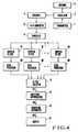
- Fig. 4 is a block diagram of an embodiment of the present invention.
- the same reference numerals in Fig. 4 denote the same portions as in the conventional technique of Fig. 1.
- the embodiment of Fig. 4 is different from the system of Fig. 1 in the following respects.
- the respective outputs from CFAR processors 8A to 8N are input to a filter selector 11.
- the filter selector 11 selects a signal having the maximum amplitude among the outputs from the respective CFAR processor in units of range bins.
- FIG. 5A shows an example of the output signal S11 from the filter selector 11.
- the relationship between the amplitudes of video signals reflected by points in predetermined ranges from the radar system and their azimuths is shown (the signals are input and output using azimuth as the time base).
- a signal level drop may occur due to the blind speed and so on of the target, as indicated at a, even in reflected signals from the target at contiguous or adjacent azimuths. When such a signal is displayed, a blip separation or incomplete blip occurs.
- the amplitude interpolator 12 compares 3 signals continuously present in adjacent azimuths in the same range.
- the signal level corresponding to the central azimuth, among the three continuous azimuths, is replaced by a signal level which is an average of the signal levels corresponding to the adjacent azimuths only when it is smaller than them.
- An output signal S12 from the amplitude interpolator 12 is free from blip separation, as shown in Fig. 5B.
- the output signal S12 from the amplitude interpolator 12 is input to and smoothed by a smoothing integrator 13 to provide a signal S13 having a waveform as shown in Fig. 5C, which is supplied to a display 14 and used for signal display.
- the maximum values of the output signals S11, S12, and S13 from the filter selector 11, the amplitude interpolator 12, and the smoothing integrator 13, respectively, are not present in the same azimuth, and a time lag exists because of the operation time, as indicated by t1, t2, and t3.
- the time lag can be compensated for by correcting the azimuth signals. In this manner, a blip separation or blip absence on the display is prevented.
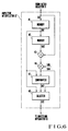
- Fig. 6 is a block diagram showing the arrangement of a first example of the amplitude interpolator 12 shown in Fig. 4.
- an amplitude interpolator 12' has memories 41 and 42, an adder 43, a multiplier 44, a comparator 47, and a selector 48.
- the memories 41 and 42 are controlled so that the signal S11 is sequentially written in and read out from them in synchronism with the output timing of the signal S11 from the filter selector 11. Therefore, the input signal S11 and output signals S41 and S42 from the memories 41 and 42, respectively, are reflected signals corresponding to points in three continuous azimuths and at the same distance from the radar system.
- the multiplier 44 is a kind of a coefficient setter, which is controlled by a multiplicand S45 set as 1/2 and produces an output 1/2 the input signal level.
- the comparator 47 compares a signal level of a certain azimuth (the memory output signal S41) with a mean value (a multiplier output signal S44) of the signal levels of the adjacent azimuths.
- S41 > S44 the comparator 47 outputs a control signal S47 to the selector 48 so that the selector 48 receives the signal S41; when S41 ⁇ S44, it outputs a control signal S47 to the selector 48 so that the selector 48 receives the signal S44.
- the selector 48 outputs either the signal S41 or S44 as the output signal S12 from the amplitude interpolator 12' in accordance with the control signal S47.
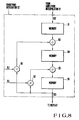
- Fig. 7 is a block diagram showing the arrangement of a second example of the amplitude interpolator.
- an amplitude interpolator 12" has memories 51 and 52, an adder 53, a multiplier 54, comparators 55 and 56, and a selector 58.
- the comparator 55 compares a multiplier output signal S54 (a mean value of signal levels of azimuths adjacent to a certain azimuth) with a threshold value S56. When S54 ⁇ S56, the comparator 55 outputs a signal S55 which deactivates the selector 58. When S54 > S56, the same operation as in Fig. 6 is performed, the comparator activates the comparator 56 and the selector 58.
- Fig. 8 is a block diagram showing an example of the smoothing integrator 13 shown in Fig. 4.
- a smoothing integrator 13' has memories 61, 64, and 66, adders 63 and 65, and multipliers 67 and 68.
- An output signal S12 within a range of a predetermined azimuth, is input to and stored in the memory 61 from the amplitude interpolator 12. Signals of azimuths in the same range are read out from the memory 61, pass the adder 63, the memory 64, the adder 65, and the memory 66, and are output as a smoothing integrator output signal S13.
- the signal S13 is applied to the adders 65 and 63 via the multipliers 67 and 68.
- the multipliers 67 and 68 also receive multiplicands K1 and K2, thus constituting a feedback integrator.
- the memories 64 and 66 store the received signal read out from the memory 61, and sequentially read out the stored signal to a next circuit after, a predetermined period of time has elapsed.
- the memories 64 and 66 serve as delay circuits.
- the multiplicands K1 and K2 are preset in order to approximate the signal S13 to the directivity of an output signal waveform shown in Fig. 5C. In this manner, signal display free from a blip separation or incomplete blip can be performed, resulting in an improvement in display and visibility azimuth precision.
Landscapes
- Engineering & Computer Science (AREA)
- Radar, Positioning & Navigation (AREA)
- Remote Sensing (AREA)
- Computer Networks & Wireless Communication (AREA)
- Physics & Mathematics (AREA)
- General Physics & Mathematics (AREA)
- Radar Systems Or Details Thereof (AREA)
Description
- The invention relates to a radar system comprising:
N Doppler filters (where N is an integer larger than 1) each of which has a configuration of a digital filter with M stages (where M is an integer); N CFAR (Constant False Alarm Rate) processing means, respectively connected to output terminals of said Doppler filters for suppressing spatially spreading clutter signals; and a video selector, connected to output terminals of said N CFAR processing means, for selecting an output signal from any one thereof. - Some recent radar systems adopt an arrangement obtained by combining MDF (Multiple Doppler Filters) processing and LOG/CFAR (Constant False Alarm Rate) processing. This arrangement serves as a means effective for detecting a target signal from an aircraft, a ship, a vehicle or the like, and removing or suppressing unwanted signals, such as ground clutter (power reflected by the ground surface, e.g., mountains, woods and forests, fields, buildings or the like), sea clutter, weather clutter (reflected power caused by a meteorogical phenomenon such as a rain cloud and snow), and so on.
- Fig. 1 is a block diagram showing a conventional radar system having such an arrangement. Referring to Fig. 1, a transmitter 1 and a receiver 4 are connected to an antenna 3 via a circulator 2. A transmitted pulse output from the transmitter 1 is input to the antenna 3 via the circulator 2 and radiated as short pulse radio waves. After the radio waves have been reflected by a target and received by the antenna 3 again, they are input to the receiver 4 via the circulator 2. The receiver 4 mixes the received radio waves with a transmission frequency component, detects a frequency component corresponding to a difference between the transmission frequency and the received waves, and supplies the frequency component to an A/
D converter 5. The A/D converter 5 converts the difference frequency component into a digital signal and supplies it to acanceller 6. When steady-state homogenously distributed signals are present, thecanceller 6 discriminates them as fixed clutter and cancels them. An output signal from thecanceller 6 is supplied to Dopplerfilters 7A to 7N. - Each of the
Doppler filters 7A to 7N extracts only a signal component within its predetermined passband. - This is based on the following principle. More specifically, various types of target and unwanted background signals have inherent relative speeds with respect to the radar. Therefore, signals received by the radar from these background signals have inherent Doppler frequency components. When an MDF consisting of a plurality of Doppler filters having different passbands is provided, these reflected signals can be separated by utilizing the differences in Doppler frequency.
- The target and clutter signals which are separatively detected by the
respective Doppler filters 7A to 7N are input to CFARprocessors 8A to 8N connected to the output terminals of theDoppler filters 7A to 7N, respectively, and are subjected to statistical normalizing processing in terms of amplitude. The principle of LOG/CFAR is as follows. Generally, a clutter signal spreads spatially uniformly since its respective reflection points that contribute to reflection exist in an area sufficiently larger than the radar range resolution defined by the pulsewidth of the radar. In contrast to this, a target signal is a point target since the physical size of a target is usually equal to or less than the radar range resolution. As a result, the clutter signal is sufficiently suppressed by LOG/CFAR processing, i.e., statistical normalizing processing in terms of amplitude in range direction, while the target signal is not, in principle, influenced by LOG/CFAR processing. In particular, it is theoretically accepted that, when the statistical characteristic of the amplitude of a clutter signal is in accordance with the Rayleigh distribution (many weather clutters and some sea clutters are known to be in accordance with the Rayleigh distribution), the clutter signal is suppressed by LOG/CFAR processing so as to have same amplitude distribution as the receiver noise. - In this manner, it is possible to separate target and clutter signals and to suppress only the clutter signal by using the Doppler
filters 7A to 7N and theCFAR processors 8A to 8N. - Referring to Fig. 1, output signals from the CFAR
processors 8A to 8N are input to an automatic target detector 9. The automatic target detector 9 conventionally performs automatic target detection in units of Doppler filter channels for the following reasons. As described above, each clutter signal has an inherent Doppler frequency and its statistical characteristic is different depending on the object contributing to reflection. When the reflecting object is an aggregate of uniform reflection points, such as rain cloud, it can often be described in accordance with the Rayleigh distribution. However, when the reflecting object is an aggregate of non-uniform reflection points, as in the case of ground clutter, it is possibly in accordance with the Weibull distribution or the Log-Normal distribution. In this manner, the amplitude distribution characteristics of a clutter signal vary depending on the type of clutter, the physical characteristic of the reflecting object, and so on, and thus amplitude distribution characteristics after MDF and LOG/CFAR processings also vary. - When automatic target detection is to be performed, a detection threshold level must be automatically controlled in order to correspond to the amplitude distribution characteristics of various remaining clutter signals after clutter suppression processing and to suppress the probability of erroneously detecting any remaining clutter signal as the target signal at a predetermined level or lower. The signal amplitude distribution characteristics differ from one Doppler filter channel to another in accordance with the presence/absence of clutter and with the type of clutter. Also, the presence/absence and the type of clutter changes from one area to another. Therefore, the automatic threshold control must be independently performed in units of Doppler filter channels.
- However, the conventional method of a radar system which carries out automatic target detection/processing in units of Doppler filter channels has the following drawbacks. First, a received signal is digitized into a binary signal by a threshold level which is preset in accordance with a remaining clutter level in units of Doppler filter channels. A target is finally discriminated. With this method, an optimally selected video signal which includes amplitude data of the target signal and also clutter which is sufficiently suppressed, and in which a partial target amplitude signal is lacking due to the canceller processing which is interpolated, cannot be obtained. Therefore, when a malfunction of an automatic target detecting/processing system, a disturbance, or an interference occurs which disables the automatic detection, a video signal allowing visual determination by an operator cannot be provided.
- Second, the number of target detection/processing systems which must be provided must coincide with the number of Doppler filter channels, resulting in a large amount of hardware.
- DE-A-3 332 634 describes a radar system of the kind defined hereinbefore at the beginning, in which each of N Doppler filters of a filter bank supplies a respective circuit that detects the amplitude of the output of the respective Doppler filter and supplies that amplitude signal to a respective CFAR unit. The outputs of the N CFAR units are supplied to a selector circuit that selects from all the target data present in the same range and sector bin of all the 1 to N Doppler-channels the analog amplitude value having the largest signal to noise ratio. This best value is used to control a selector switch that selects the corresponding output from the respective amplitude detecting circuit for input to further signal processing apparatus.
- It is, therefore, an object of the present invention to provide a high operability, economical radar system in which the above drawbacks are removed and which can provide an optimum video signal as well as symbol representation as a result of automatic target detection.
- According to the present invention, a radar system of the kind defined hereinbefore at the beginning is characterised by amplitude interpolating means for providing analog video such that when a signal level of an azimuth of interest, among output signals from said selector that are continuous in adjacent azimuths in a predetermined range, is smaller than a value uniquely determined as a function of adjacent signal levels, the value uniquely determined as the function of the adjacent signal levels is used as a value representing an output of the azimuth of interest in the predetermined range; and
integrating means for performing smoothing integration of the output from said amplitude interpolating means with respect to predetermined azimuths in a predetermined range, the video selector selecting the said output signal in units of radar range bins and synthesizing N channel signals into a single channel signal. - The invention will now be described by way of example with reference to the accompanying drawings, in which:-
- Fig. 1 is a block diagram for explaining a radar system of a conventional technique;
- Fig. 2 is a block diagram showing another radar system;
- Fig. 3 shows waveform charts for explaining the operation of the radar system shown in Fig. 2;
- Fig. 4 is a block diagram showing a radar system embodying the present invention;
- Figs. 5A to 5C are graphs for explaining the output waveforms from the major portions of the circuit shown in Fig. 4;
- Fig. 6 is a circuit diagram of an example of an amplitude interpolator shown in Fig. 4;
- Fig. 7 is a circuit diagram of another example of the amplitude interpolator shown in Fig. 4; and
- Fig. 8 is a circuit diagram of an example of a smoothing integrator shown in Fig. 4.
- The radar system shown in Fig. 2 has a received signal
video input terminal 15, an A/D converter 20,Doppler filters 30₁ to 30N, LOG/CFARs 31₁ to 31N, automatic gain controllers (AGCs) 32₁ to 32N, avideo selector 33, an automatictarget detection processor 34, asmoothing video integrator 35, a D/A converter 36, an automatic target detectionsignal output terminal 37, and a reproduced processed videosignal output terminal 38. - Referring to Fig. 2, a received video signal is input to the A/
D converter 20 from theinput terminal 15 and is applied to the N-channel Doppler filters 30₁ to 30N in parallel to each other. TheDoppler filters 30₁ to 30N have different pass bands so as to cover the entire Doppler frequency band with the N channels. Therefore, various target and clutter signals having different Doppler frequencies are divided into the separate Doppler filters. Target and clutter signals having the same Doppler frequency pass the same Doppler filter. In any event, a signal divided in units of Doppler frequency bands is subjected to mean value division by the LOG/CFARs 31₁ to 31N. A clutter signal spreading in the range direction is suppressed by the LOG/CFARs to a level corresponding to that of receiver noise, and a target signal which exists only in a pulse-like manner in the range direction is passed through the LOG/CFARs with merely a small processing loss. In this manner, clutter suppress processing is completed, and automatic target detection processing is started. - The various clutter signals are divided by a mean value level and suppressed by the LOG/
CFARs 31₁ to 31N. The amplitude distribution characteristics after suppress processing are not uniform because of the amplitude distribution characteristics of the clutter signals. Automatic gain control is performed by theAGCs 32₁ to 32N in order to control the clutter signals so that the remaining clutter levels become the same, i.e., so that the probabilities of erroneously determining the remaining clutter signal as the target become the same among the N-channel Doppler filter channels. - The
AGCs 32₁ to 32N can detect a maximum value of a remaining signal amplitude after LOG/CFAR processing within a predetermined range, and perform automatic gain control in order to give attenuation proportional to the detected maximum amplitude. In this manner, a maximum value of the level-controlled N-channel signals is selected by thevideo selector 33 in units of the range bins, and the selected signals are synthesized into a 1-channel signal. - After maximum value selection and synthesis, the signal is subjected to target detection processing by the 1-channel automatic
target detection processor 34, in a similar manner to the conventional radar system which does not have MDF, and is output from theoutput terminal 37. - It must be noted that, when a Weibull CFAR processing means is used as the CFAR processing means, a clutter suppression effective for a signal in accordance with the Weibull distribution, as ground clutter, can be obtained.
- After maximum value selection and synthesis, the signal is also subjected to video reproduction by the smoothing
video integrator 35 in order to reproduce a video signal for visual discrimination by the radar operator. - More specifically, in this embodiment MDF processing is performed once per N hits. Therefore, in the output from the
video selector 33, a single signal per N hits is obtained, i.e., signals for N-1 hits are omitted. In order to reproduce these absent components, a signal per N hits is interpolated by feedback integrator processing, and a signal for each hit is thus output. - Fig. 3 shows waveform charts for explaining the change of a point target signal due to MDF processing and video reproduction processing. Fig. 3(a) shows an amplitude change of a received video signal with respect to an ideal point target. Fig. 3(b) shows an amplitude change of a point target when N = 5 after the signal shown in Fig. 3(a) is subjected to MDF processing. More specifically, one signal per 5 hits is shown in Fig. 3(b) and 4-hit signal components are absent. Fig. 3(c) shows a signal waveform wherein the absent signal components are reproduced with pseudo signals having the same amplitude as that which has been received at first. When the thus-obtained signal is smoothed by the feedback integrator, a signal waveform as shown in Fig. 3(d), which is substantially the same as that shown in Fig. 3(a) and adequate for visual discrimination by the operator, can be obtained. The video signal processed in this manner is converted into an analog video signal by the D/
A converter 36 and is supplied to a radar display from theoutput terminal 38. - As described above, in the radar system signals of a plurality of channels which have been subjected to MDF processing and CFAR processing are synthesized into a single channel signal while any one channel is selected by the selector in units of range bins. Thereafter a target is detected. Therefore, only a single automatic target detection processing system is needed, and the hardware can be considerably less than that of a conventional system.
- A signal component of a frequency which is absent due to MDF processing is interpolated by a video reproducing means from a signal synthesized into one channel, and hence an optimum video signal can be provided. Thus, the radar video signal can be displayed to allow the operator to discriminate the presence/absence of the target as needed.
- Fig. 4 is a block diagram of an embodiment of the present invention. The same reference numerals in Fig. 4 denote the same portions as in the conventional technique of Fig. 1. The embodiment of Fig. 4 is different from the system of Fig. 1 in the following respects. In Fig. 4, the respective outputs from
CFAR processors 8A to 8N are input to afilter selector 11. Thefilter selector 11 selects a signal having the maximum amplitude among the outputs from the respective CFAR processor in units of range bins. - A signal S11 output from the
filter selector 11 is suppled to anamplitude interpolator 12. Fig. 5A shows an example of the output signal S11 from thefilter selector 11. In Fig. 5A, the relationship between the amplitudes of video signals reflected by points in predetermined ranges from the radar system and their azimuths is shown (the signals are input and output using azimuth as the time base). As shown in Fig. 5A, a signal level drop may occur due to the blind speed and so on of the target, as indicated at a, even in reflected signals from the target at contiguous or adjacent azimuths. When such a signal is displayed, a blip separation or incomplete blip occurs. As as result, when the operator monitors the display, he may erroneously identify a blip or the azimuth measuring precision may be degraded. Theamplitude interpolator 12 compares 3 signals continuously present in adjacent azimuths in the same range. The signal level corresponding to the central azimuth, among the three continuous azimuths, is replaced by a signal level which is an average of the signal levels corresponding to the adjacent azimuths only when it is smaller than them. An output signal S12 from theamplitude interpolator 12 is free from blip separation, as shown in Fig. 5B. When the reflected signal level is smaller than a certain threshold level, i.e., when the reflected signal cannot be distinguished from noise, the above processing is not performed so as not to emphasize the blip of a remaining clutter signal or a noise signal. - The output signal S12 from the
amplitude interpolator 12 is input to and smoothed by a smoothingintegrator 13 to provide a signal S13 having a waveform as shown in Fig. 5C, which is supplied to adisplay 14 and used for signal display. - As is apparent from Figs. 5A, 5B, and 5C, the maximum values of the output signals S11, S12, and S13 from the
filter selector 11, theamplitude interpolator 12, and the smoothingintegrator 13, respectively, are not present in the same azimuth, and a time lag exists because of the operation time, as indicated by t1, t2, and t3. However, the time lag can be compensated for by correcting the azimuth signals. In this manner, a blip separation or blip absence on the display is prevented. - Fig. 6 is a block diagram showing the arrangement of a first example of the
amplitude interpolator 12 shown in Fig. 4. Referring to Fig. 6, an amplitude interpolator 12' hasmemories multiplier 44, acomparator 47, and aselector 48. Thememories filter selector 11. Therefore, the input signal S11 and output signals S41 and S42 from thememories multiplier 44 is a kind of a coefficient setter, which is controlled by a multiplicand S45 set as 1/2 and produces an output 1/2 the input signal level. Thus, thecomparator 47 compares a signal level of a certain azimuth (the memory output signal S41) with a mean value (a multiplier output signal S44) of the signal levels of the adjacent azimuths. When S41 > S44, thecomparator 47 outputs a control signal S47 to theselector 48 so that theselector 48 receives the signal S41; when S41 < S44, it outputs a control signal S47 to theselector 48 so that theselector 48 receives the signal S44. Theselector 48 outputs either the signal S41 or S44 as the output signal S12 from the amplitude interpolator 12' in accordance with the control signal S47. - Fig. 7 is a block diagram showing the arrangement of a second example of the amplitude interpolator. Referring to Fig. 7, an
amplitude interpolator 12" hasmemories adder 53, amultiplier 54,comparators selector 58. Thecomparator 55 compares a multiplier output signal S54 (a mean value of signal levels of azimuths adjacent to a certain azimuth) with a threshold value S56. When S54 < S56, thecomparator 55 outputs a signal S55 which deactivates theselector 58. When S54 > S56, the same operation as in Fig. 6 is performed, the comparator activates thecomparator 56 and theselector 58. - Fig. 8 is a block diagram showing an example of the smoothing
integrator 13 shown in Fig. 4. A smoothing integrator 13' hasmemories adders multipliers memory 61 from theamplitude interpolator 12. Signals of azimuths in the same range are read out from thememory 61, pass theadder 63, thememory 64, theadder 65, and thememory 66, and are output as a smoothing integrator output signal S13. At the same time, the signal S13 is applied to theadders multipliers multipliers - The
memories memory 61, and sequentially read out the stored signal to a next circuit after, a predetermined period of time has elapsed. Thememories
Claims (7)
- A radar system comprising:
N Doppler filters (30₁ to 30N), where N is an integer larger than 1, each of which has a configuration of a digital filter with M stages, where M is an integer;
N CFAR (Constant False Alarm Rate) processing means (31₁ to 31N), respectively connected to output terminals of said Doppler filters for suppressing spatially spreading clutter signals; and
a video selector (33), connected to output terminals of said N CFAR processing means, for selecting an output signal from any one thereof, characterised by amplitude interpolating means (12) for providing analog video such that when a signal level of an azimuth of interest, among output signals from said selector (33) that are continuous in adjacent azimuths in a predetermined range, is smaller than a value uniquely determined as a function of adjacent signal levels, the value uniquely determined as the function of the adjacent signal levels is used as a value representing an output of the azimuth of interest in the predetermined range; and
integrating means (13) for performing smoothing integration of the output from said amplitude interpolating means (33) with respect to predetermined azimuths in a predetermined range, the video selector (33) selecting the said output signal in units of radar range bins and synthesizing N channel signals into a single channel signal. - A radar system according to claim 1, characterised in that the CFAR processing means (31₁ to 31N) are Weibull CFAR processing means capable of subjecting a signal having Weibull distribution characteristics as amplitude characteristics to CFAR processing.
- A radar system according to claim 1, characterised in that the CFAR processing means (31₁ to 31N) comprise LOG/CFAR processing means capable of subjecting a signal having Rayleigh distribution characteristics as amplitude characteristics to CFAR processing, and that automatic gain adjusting means (32₁ to 32N) are connected to an output terminal of said LOG/CFAR processing means, for adapting to a remaining signal obtained by subjecting a signal having amplitude characteristics of a non-Rayleigh distribution to LOG/CFAR processing, and for converting the remaining signal into a signal having equivalent amplitude level to that of the receiver noise signal.
- A radar system according to claim 3, characterised in that the automatic gain adjusting means (32₁ to 32N) comprises means for detecting a maximum value of an amplitude of the remaining signal within a predetermined range after LOG/CFAR processing, and means which performs automatic gain adjustment in order to give an attenuation proportional to the detected maximum amplitude.
- A radar system according to claim 1, characterised in that the amplitude interpolating means (12;12') further has:
first and second memories (41,42), connected in series with each other, for sequentially storing and outputting an input signal at an input timing of the input signal;
an arithmetic operational circuit (43,44) for calculating half of the sum of the input signal and an output from said second memory (42); and
comparing/selecting means (47,48) for comparing an output from said arithmetic operational circuit (43,44) with an output from said first memory (41) and outputting a larger output. - A radar system according to claim 5, characterised in that the amplitude interpolating means (12; 12'; 12") further comprises a comparator (55) for comparing the output from said arithmetic operational circuit (43,44) and a preset threshold value and, when the output is larger than the threshold value, activating said comparing/selecting means (47,48; 56,58).
- A radar system according to claim 5, characterised in that the smoothing integrating means (13; 13') has memories (61, 64, 66), connected in series with each other to constitute a delay circuit, means (63,65) for adding to an output from each of said memories (61,64) except the last memory (66) a product obtained by multiplying an output from the last memory (66) by a predetermined multiplicand, and for inputting the obtained sum to the respective next memory.
Applications Claiming Priority (4)
| Application Number | Priority Date | Filing Date | Title |
|---|---|---|---|
| JP289787/85 | 1985-12-23 | ||
| JP28978785A JPS62148873A (en) | 1985-12-23 | 1985-12-23 | Radar equipment |
| JP61008590A JPS62165174A (en) | 1986-01-17 | 1986-01-17 | Radar device |
| JP8590/86 | 1986-01-17 |
Publications (3)
| Publication Number | Publication Date |
|---|---|
| EP0227457A2 EP0227457A2 (en) | 1987-07-01 |
| EP0227457A3 EP0227457A3 (en) | 1989-06-14 |
| EP0227457B1 true EP0227457B1 (en) | 1993-09-15 |
Family
ID=26343135
Family Applications (1)
| Application Number | Title | Priority Date | Filing Date |
|---|---|---|---|
| EP86309992A Expired - Lifetime EP0227457B1 (en) | 1985-12-23 | 1986-12-22 | Radar system |
Country Status (3)
| Country | Link |
|---|---|
| US (1) | US4839655A (en) |
| EP (1) | EP0227457B1 (en) |
| DE (1) | DE3689037D1 (en) |
Families Citing this family (14)
| Publication number | Priority date | Publication date | Assignee | Title |
|---|---|---|---|---|
| NL8800002A (en) * | 1988-01-04 | 1988-04-05 | Hollandse Signaalapparaten Bv | MOVING TARGET INDICATION UNIT. |
| FR2628909B1 (en) * | 1988-03-18 | 1990-07-13 | Thomson Csf | METHOD AND DEVICES FOR TRANSLATION ALONG THE FREQUENCY AXIS OF THE MODULE OF THE TRANSFER FUNCTION OF A FILTER |
| US5140332A (en) * | 1989-07-13 | 1992-08-18 | Westinghouse Electric Corp. | Short pulse radar system with a long pulse transmitter |
| GB2274037B (en) * | 1992-12-30 | 1997-07-23 | Samsung Electronics Co Ltd | Video signal main processor for radar system |
| US5357256A (en) * | 1993-08-17 | 1994-10-18 | Alliedsignal Inc. | Radar receiver with adaptive clutter threshold reference |
| US5416488A (en) * | 1993-12-27 | 1995-05-16 | Motorola, Inc. | Radar return signal processing method |
| US6085151A (en) * | 1998-01-20 | 2000-07-04 | Automotive Systems Laboratory, Inc. | Predictive collision sensing system |
| IL175465A (en) * | 2005-10-19 | 2013-02-28 | Elta Systems Ltd | Pulse doppler coherent method and system for snr enhancement |
| ES2369862T3 (en) * | 2006-11-02 | 2011-12-07 | Raytheon Canada Limited | MOBILE WHITE DETECTOR FOR RADAR SYSTEMS. |
| GB2451242A (en) * | 2007-07-23 | 2009-01-28 | Thales Holdings Uk Plc | Signal processing system for pulse doppler radar |
| EP2345909A1 (en) * | 2010-01-07 | 2011-07-20 | BAE Systems PLC | A method of detecting a clutter return at a sensor |
| PL2521927T3 (en) * | 2010-01-07 | 2017-08-31 | Bae Systems Plc | A method of detecting a clutter return at a sensor |
| CA2774377C (en) | 2012-02-02 | 2017-05-02 | Raytheon Canada Limited | Knowledge aided detector |
| RU2626380C1 (en) * | 2016-10-21 | 2017-07-26 | федеральное государственное автономное образовательное учреждение высшего образования "Южный федеральный университет" | Selection system of moving targets with measurement of range, radial velocity and direction of motion |
Family Cites Families (16)
| Publication number | Priority date | Publication date | Assignee | Title |
|---|---|---|---|---|
| US3587097A (en) * | 1966-12-05 | 1971-06-22 | Westinghouse Electric Corp | Signal retrieval system with continuous control of detection threshold level |
| US3968490A (en) * | 1974-05-03 | 1976-07-06 | General Electric Company | Radar MTI processor with CFAR |
| FR2377640A1 (en) * | 1977-01-18 | 1978-08-11 | Thomson Csf | DEVICE FOR STABILIZING THE RATE OF FALSE ALARMS IN A RADAR AND RADAR SYSTEM INCLUDING SUCH A DEVICE |
| US4137532A (en) * | 1977-04-29 | 1979-01-30 | Westinghouse Electric Corp. | VIP doppler filter bank signal processor for pulse doppler radar |
| JPS55122173A (en) * | 1979-03-14 | 1980-09-19 | Nec Corp | Noise suppression circuit |
| US4249177A (en) * | 1979-05-03 | 1981-02-03 | The United States Of America As Represented By The Secretary Of The Air Force | Target discrimination apparatus |
| US4488154A (en) * | 1980-04-25 | 1984-12-11 | Raytheon Company | Radar processor |
| JPS57165774A (en) * | 1981-04-03 | 1982-10-12 | Nec Corp | General purpose control device for rate of erroneously issued alarm |
| US4503432A (en) * | 1981-12-17 | 1985-03-05 | The United States Of America As Represented By The Secretary Of The Army | Adaptive threshold detection utilizing a tapped charge transfer device delay line |
| IT1189312B (en) * | 1982-07-08 | 1988-02-04 | Selenia Ind Elettroniche | Device for post detection cancelling of erroneous radar echoes |
| IT1168614B (en) * | 1983-07-15 | 1987-05-20 | Selenia Ind Elettroniche | MTD DIGITAL PROCESSOR FOR SEARCH RADAR WITH BENCH OF DOPPLER FILTERS AND SYSTEM OF SELF-ADJUSTABLE THRESHOLDS DEPENDING ON THE DISORDER |
| JPS6024476A (en) * | 1983-07-21 | 1985-02-07 | Nec Corp | Radar equipment |
| DE3332634C2 (en) * | 1983-09-09 | 1985-07-25 | Siemens AG, 1000 Berlin und 8000 München | Circuit arrangement for the detection of moving targets in radar receivers |
| US4586043A (en) * | 1984-03-21 | 1986-04-29 | The United States Of America As Represented By The Secretary Of The Air Force | Distribution sensitive constant false alarm rate (CFAR) processor |
| US4622556A (en) * | 1984-10-02 | 1986-11-11 | The United States Of America As Represented By The Secretary Of The Air Force | Technique for rapid determination of probability of detection in pulse doppler radars |
| US4672380A (en) * | 1984-10-02 | 1987-06-09 | The United States Of America As Represented By The Secretary Of The Air Force | Gain restoration after doppler filtering |
-
1986
- 1986-12-22 EP EP86309992A patent/EP0227457B1/en not_active Expired - Lifetime
- 1986-12-22 DE DE86309992T patent/DE3689037D1/en not_active Expired - Lifetime
-
1989
- 1989-06-13 US US06/945,693 patent/US4839655A/en not_active Expired - Fee Related
Also Published As
| Publication number | Publication date |
|---|---|
| EP0227457A2 (en) | 1987-07-01 |
| US4839655A (en) | 1989-06-13 |
| DE3689037D1 (en) | 1993-10-21 |
| EP0227457A3 (en) | 1989-06-14 |
Similar Documents
| Publication | Publication Date | Title |
|---|---|---|
| EP0227457B1 (en) | Radar system | |
| JP3388506B2 (en) | Pulse Doppler radar system with improved cluster target resolution | |
| US5798728A (en) | Radar signal processing apparatus | |
| US4713664A (en) | Point clutter threshold determination for radar systems | |
| US4885590A (en) | Blind speed elimination for dual displaced phase center antenna radar processor mounted on a moving platform | |
| US4021805A (en) | Sidelobe blanking system | |
| US4654665A (en) | Radar system | |
| US5229775A (en) | Digital pulse compression apparatus | |
| US4488154A (en) | Radar processor | |
| US4058809A (en) | MTI system and method | |
| US4649389A (en) | Stacked beam radar and target height measurement extractor especially for use therein | |
| US5017921A (en) | Radar system and a method for operating a radar system | |
| US4714927A (en) | Pulse doppler radar with variable pulse repetition rate | |
| US4439765A (en) | Radar video processor | |
| US5546089A (en) | Optical monopulse chirp processor | |
| US4963888A (en) | Single-scan editor of bird echoes | |
| CA1246194A (en) | Pulse radar apparatus | |
| EP0054982B1 (en) | Threshold circuit for radar video data | |
| US4727375A (en) | Process for adapting the post integration in a switched pulse repetition frequency radar and a circuit implementing this process | |
| CA2082219A1 (en) | Frequency interrupt continuous transmit active sonar transmission and signal processing technique | |
| US4649395A (en) | Pulse radar apparatus | |
| US3623095A (en) | Pulse radar system | |
| JPH0521513B2 (en) | ||
| JPH05203733A (en) | Radar apparatus | |
| EP0057949B1 (en) | Pulse radar apparatus |
Legal Events
| Date | Code | Title | Description |
|---|---|---|---|
| PUAI | Public reference made under article 153(3) epc to a published international application that has entered the european phase |
Free format text: ORIGINAL CODE: 0009012 |
|
| 17P | Request for examination filed |
Effective date: 19870112 |
|
| AK | Designated contracting states |
Kind code of ref document: A2 Designated state(s): DE FR GB |
|
| PUAL | Search report despatched |
Free format text: ORIGINAL CODE: 0009013 |
|
| AK | Designated contracting states |
Kind code of ref document: A3 Designated state(s): DE FR GB |
|
| 17Q | First examination report despatched |
Effective date: 19920121 |
|
| GRAA | (expected) grant |
Free format text: ORIGINAL CODE: 0009210 |
|
| AK | Designated contracting states |
Kind code of ref document: B1 Designated state(s): DE FR GB |
|
| PG25 | Lapsed in a contracting state [announced via postgrant information from national office to epo] |
Ref country code: FR Effective date: 19930915 Ref country code: DE Effective date: 19930915 |
|
| REF | Corresponds to: |
Ref document number: 3689037 Country of ref document: DE Date of ref document: 19931021 |
|
| PGFP | Annual fee paid to national office [announced via postgrant information from national office to epo] |
Ref country code: GB Payment date: 19931216 Year of fee payment: 8 |
|
| EN | Fr: translation not filed | ||
| PLBE | No opposition filed within time limit |
Free format text: ORIGINAL CODE: 0009261 |
|
| STAA | Information on the status of an ep patent application or granted ep patent |
Free format text: STATUS: NO OPPOSITION FILED WITHIN TIME LIMIT |
|
| 26N | No opposition filed | ||
| PG25 | Lapsed in a contracting state [announced via postgrant information from national office to epo] |
Ref country code: GB Effective date: 19941222 |
|
| GBPC | Gb: european patent ceased through non-payment of renewal fee |
Effective date: 19941222 |