EP0227164A2 - Integrated services digital information transmission system with devices for the simultaneous transmission of broad-band and narrow-band signals - Google Patents
Integrated services digital information transmission system with devices for the simultaneous transmission of broad-band and narrow-band signals Download PDFInfo
- Publication number
- EP0227164A2 EP0227164A2 EP86202172A EP86202172A EP0227164A2 EP 0227164 A2 EP0227164 A2 EP 0227164A2 EP 86202172 A EP86202172 A EP 86202172A EP 86202172 A EP86202172 A EP 86202172A EP 0227164 A2 EP0227164 A2 EP 0227164A2
- Authority
- EP
- European Patent Office
- Prior art keywords
- signal
- amplitude
- narrowband
- broadband
- transmission
- Prior art date
- Legal status (The legal status is an assumption and is not a legal conclusion. Google has not performed a legal analysis and makes no representation as to the accuracy of the status listed.)
- Withdrawn
Links
Images

Classifications
-
- H—ELECTRICITY
- H04—ELECTRIC COMMUNICATION TECHNIQUE
- H04L—TRANSMISSION OF DIGITAL INFORMATION, e.g. TELEGRAPHIC COMMUNICATION
- H04L5/00—Arrangements affording multiple use of the transmission path
- H04L5/02—Channels characterised by the type of signal
- H04L5/04—Channels characterised by the type of signal the signals being represented by different amplitudes or polarities, e.g. quadriplex
-
- H—ELECTRICITY
- H04—ELECTRIC COMMUNICATION TECHNIQUE
- H04J—MULTIPLEX COMMUNICATION
- H04J7/00—Multiplex systems in which the amplitudes or durations of the signals in individual channels are characteristic of those channels
-
- H—ELECTRICITY
- H04—ELECTRIC COMMUNICATION TECHNIQUE
- H04J—MULTIPLEX COMMUNICATION
- H04J14/00—Optical multiplex systems
Abstract
In einem zukünftigen Breitband-ISDN mit vorzugsweise optischer Teilnehmeranschlußleitung kann der Teilnehmer nicht nur auf die schmalbandigen ISDN-Dienste sondern auch auf die Breitband-Dienste (z.B. Bewegtbilddienste) zugreifen. Zur übertragungstechnischen Integration von niederratigen ISDN-Signalen und hochratigen Breitbandsignalen kann die elektrische Multiplexbildung durch eine Überlagerung dieser Signale in voneinander getrennten Frequenzübertragungsbereichen (Frequenzmultiplex) oder unter Anwendung einer Amplituden- oder Phasenmodulation des hochratigen Signals vorgenommen werden. Zur Vermeidung der bei Frequenzmultiplex für gute Übertragungsqualität verlangten hohen Filter- und Linearitätsanforderung bzw. zur Sicherstellung eines Notbetriebs ohne das hochratige Signal, welcher bei einem Modulations-Verfahren oder Zeitmultiplex-Verfahren erschwert ist, wird eine amplitudenmäßige Überlagerung der beiden Signale in sich möglicherweise überlappenden Frequenzbändern vorgenommen. Sendeseitig werden das Schmalbandund das Breitbandsignal mit einer vom Bitratenverhältnis abhängigen Gewichtung einander additiv überlagert und empfangsseitig wird aus dem in der Amplitude mehrstufigen Summensignal das Schmalbandsignal durch AmplitudenHüll-kurven-Demodulation und das Breitbandsignal durch Amplitudenbegrenzung zurückgewonnen.In a future broadband ISDN with preferably an optical subscriber line, the subscriber can not only access the narrowband ISDN services but also the broadband services (e.g. moving picture services). For the transmission-technical integration of low-rate ISDN signals and high-rate broadband signals, the electrical multiplex formation can be carried out by superimposing these signals in separate frequency transmission ranges (frequency multiplexing) or by using an amplitude or phase modulation of the high-rate signal. In order to avoid the high filter and linearity requirements required for frequency division multiplexing for good transmission quality or to ensure emergency operation without the high-rate signal, which is more difficult with a modulation method or time division multiplexing method, an amplitude-like superposition of the two signals in possibly overlapping frequency bands becomes possible performed. On the transmission side, the narrowband and the broadband signal are additively superimposed on one another with a weighting that depends on the bit rate ratio, and on the receiving side, the narrowband signal is recovered from the multistage amplitude signal by amplitude envelope demodulation and the broadband signal by limiting the amplitude.
Description
Die Erfindung betrifft ein diensteintegrierendes, digitales Nachrichtenübertragungssystem gemäß dem Oberbegriff des Patentanspruchs 1.The invention relates to an integrated service digital message transmission system according to the preamble of
Beim Aufbau eines diensteintegrierenden digitalen Nachrichtennetzes ISDN sind für die Zusammenarbeit zwischen Geräten der Sprach-, Text-, Daten- und Bildkommunikation Vorkehrungen für den Netzzugang und die Kommunikationsabwicklung zu treffen. In der Zeitschrift telcom report 6 (1983) Heft 3, Seiten 166 ff. ist die Architektur des Teilnehmerzugangs beschrieben, welche in der CCITT-Empfehlung I. 430 festgelegt worden ist. An der Schnittstelle zwischen Netz und Teilnehmer, der sogenannten SO-Schnittstelle, stehen für die Nachrichtenübertragung gleichzeitig und in beiden Richtungen zwei Nutzkanäle (B-Kanäle) mit jeweils 64 kbit/s und ein Signalisierungskanal (D-Kanal) mit 16kbit/s zur Verfügung.When setting up an integrated digital communications network ISDN, precautions must be taken for network access and communication processing for the cooperation between devices for voice, text, data and image communication. In the magazine telcom report 6 (1983), issue 3, pages 166 ff., The architecture of the subscriber access is described, which was defined in the CCITT recommendation I. 430. At the interface between the network and the subscriber, the so-called SO interface, two user channels (B channels) with 64 kbit / s each and one signaling channel (D channel) with 16 kbit / s are available for message transmission simultaneously and in both directions .
Über den D-Kanal wird die für beide B-Kanäle erforderliche Teilnehmersignalisierung übertragen. Diese Teilnehmersignalisierung umfaßt das Übermitteln allgemeiner Informationen zwischen angeschlossenen Teilnehmer-Endgeräten und Netz, z.B. über vorliegende und nicht erledigte fremde Verbindungswünsche, Gebührenhinweise, sowie das Übermitteln von Informationen zur dienstspezifischen Behandlung der Verbindungen auf den B-Kanälen einschließ-B-Kanälen einschließlich der Steuerung des Verbindungsaufbaus bei wechselnder Endgerätenkonfiguration (Teilnehmerstationen mit mehreren Geräten an einem Anschluß).The subscriber signaling required for both B channels is transmitted via the D channel. This subscriber signaling includes the transmission of general information between connected subscriber terminals and the network, for example about existing and unresolved external connection requests, fee information, and the transmission of information for service-specific handling of the connections on the B channels, including B channels including the control of the connection establishment with changing terminal configuration (subscriber stations with several devices on one connection).
Die Teilnehmerstationen sind im ISDN mit einem sogenannten Netzabschluß NT verbunden, welcher über die Anschlußleitung mit einem Leitungsabschluß LT der Vermittlungsstelle verbunden ist. LeitungsabschluB LT und Netzabschluß NT übernehmen die übertragungstechnischen Aufgaben des Sendens und Empfangens der Schmalbandsignale mit einer Nettobitrate von 144 kbit/s, womit die Aufgaben der Taktversorgung und Synchronisierung, der Fehlereingrenzung durch Schleifenbildung und der Fernspeisung verbunden sind.The subscriber stations in ISDN are connected to a so-called network termination NT, which is connected via the connecting line to a line termination LT of the exchange. Line termination LT and network termination NT take over the transmission-related tasks of sending and receiving the narrowband signals with a net bit rate of 144 kbit / s, with which the tasks of clock supply and synchronization, error limitation by looping and remote feeding are connected.
An der SO-Schnittstelle können im ISDN bis zu acht Endge- : räte angeschlossen werden, welche unabhängig voneinander auf den D-Kanal zugreifen können. Um zu erreichen, daß während ein Teilnehmer-Endgerät die Nachricht überträgt nicht andere Teilnehmer-Endgeräte mit der Nachrichtenübertragung beginnen, ist in der CCITT-Empfehlung I. 430 festgelegt, daß zunächst alle von den Endgeräten über den D-Kanal zum NetzabschluB gelangenden D-Bits neben ihrer Übertragung zur Vermittlungsstelle einzeln in einem speziellen D-Echokanal über die SO-Schnittstelle zu den Endgeräten zurückgesendet werden. Die elektrischen Eigenschaften der SO-Schnittstelle sind so gewählt, daß eine logische "0" immer dominiert, wenn verschiedene Endgeräte gleichzeitig eine logische "0" und eine logische "1" im D-Kanal senden (wired-or). Im D-Echokanal (E-Bit) wird vom Netzabschluß NT eine logische "0" zurückgesendet, so daß jenes Endgerät, welches zum Netzabschluß NT eine logische "1" gesendet hat, diese Abweichung erkennt und seine Meldung noch vor dem Aussenden des nächsten D-Bits abbricht.Up to eight end devices can be connected to the SO interface in ISDN: They can access the D channel independently of each other. In order to ensure that while a subscriber terminal is transmitting the message, other subscriber terminals are not beginning to transmit the message, CCITT recommendation I. 430 stipulates that first all D- from the terminals to the network termination via the D channel In addition to their transmission to the exchange, bits are individually sent back to the terminals in a special D-echo channel via the SO interface. The electrical properties of the SO interface are selected so that a logical "0" always dominates when different terminals simultaneously send a logical "0" and a logical "1" in the D channel (wired-or). In the D-echo channel (E-bit) a logical "0" is sent back from the network termination NT, so that the terminal which sent a logical "1" to the network termination NT recognizes this deviation and its message before the next one is sent D bits aborts.
In einem zukünftigen Breitband-ISDN mit vorzugsweise optischer Teilnehmeranschlußleitung sind außer den vorgenannten ISDN-Schmalband-Diensten Dienste mit höheren Ubertragungsbitraten (z.B. Bewegtbilddienste) geplant. Während bei der Benutzung bestehender Kupferleitungen diese Integration auf Dienste beschränkt ist, die mit höchstens zwei 64 kbit/s-B-Kanälen auskommen, entfallen hierbei Einschränkungen bezüglich der Kapazität der Anschlußleitung. Zum Netzzugang an der Breitband-Schnittstelle, beim Anschluß eines Breitband-Endgeräts, ist im Hinblick auf die Integration von Breitband-Diensten auf der Teilnehmeranschlußleitung ein Zugriffsverfahren festzulegen. Soll der Zugriff des Breitband-Endgeräts unter Anwendung des in der CCITT-Empfehlung I. 430 festgelegten Zugriffsverfahren erfolgen, so ist eine mögliche Lösung hierfür der Anschluß des Breitband-Endgeräts über ein Leitungsvielfach an den Netzabschluß NT. Das Breitband-Endgerät ist hierfür einerseits wie ein Schmalband-Endgerät an den SO-Bus angeschlossen und ist andererseits parallel hierzu über einen Breitbandanschluß (auf dem ausschließlich die Breitbandinformation übertragen wird) an den Netzabschluß NT angeschlossen. Eine solche Lösung des gemeinsamen D-Kanal-Zugriffs weist den Nachteil auf, daß zwischen dem Breitband-Endgerät und dem SO-Bus eine zusätzliche Leitung erforderlich ist, wodurch die Forderung nach einer bereits im Endgerät erfolgenden übertragungstechnischen Integration nicht erfüllt ist.In a future broadband ISDN with preferably an optical subscriber line, services with higher transmission bit rates (e.g. moving picture services) are planned in addition to the aforementioned ISDN narrowband services. While using existing copper lines this integration is limited to services that can manage with a maximum of two 64 kbit / s-B channels, there are no restrictions regarding the capacity of the connecting line. For network access at the broadband interface, when connecting a broadband terminal, an access procedure must be defined with regard to the integration of broadband services on the subscriber line. If the broadband terminal is to be accessed using the access procedure specified in CCITT recommendation I. 430, a possible solution for this is to connect the broadband terminal to the network termination NT via a multiple line. For this purpose, the broadband terminal is connected to the SO bus like a narrowband terminal and is connected to the network termination NT in parallel via a broadband connection (on which only the broadband information is transmitted). Such a solution for common D-channel access has the disadvantage that an additional line is required between the broadband terminal and the SO bus, as a result of which the requirement for a transmission technology integration already taking place in the terminal is not met.
Aus der EP-B1 0 053 236 ist ein dienstintegriertes, digitales Übertragungssystem bekannt, bei dem sendeseitig eine Überlagerung eines niederratigen und eines hochratigen Signals in voneinander getrennten Frequenzübertragungsbereichen vorgenommen wird. Empfangsseitig wird das empfangene Summensignal durch Frequenzfilterung in das niederratige und das hochratige Signal wieder zerlegt. Für die dabei vorgenommene frequenzmäßige Trennung des niederratigen und hochratigen Signals sind steilflankige LC-Filter erforderlich, wobei die Frequenz-spektren des niederratigen und hochratigen Signals genügend weit auseinander liegen müssen. Weiterhin weist das aus der EP-B1 0 053 236 bekannte dienstintegrierte, digitale Übertragungssystem den Nachteil auf, daß durch Nichtlinearitäten bei der Übertragung auftretende Intermodulationsprodukte mittels Frequenzfilterung nicht zu beseitigen sind und dadurch die Übertragungsqualität beeinträchtigt wird.From EP-B1 0 053 236 a service-integrated, digital transmission system is known, in which a low-rate and a high-rate signal are superimposed in separate frequencies on the transmission side areas of responsibility. At the receiving end, the received sum signal is broken down into the low-rate and the high-rate signal by frequency filtering. Steep-flanked LC filters are required for the frequency separation of the low-rate and high-rate signals, the frequency spectra of the low-rate and high-rate signals having to be sufficiently far apart. Furthermore, the service-integrated digital transmission system known from EP-
Weiterhin ist aus der EP-Al 0 135 164 ein Übertragungssystem für digitale Signale hoher Schrittgeschwindigkeit mit Zusatzsignalübertragung bekannt, bei dem das niederratige Signal einem hochratigen Signal phasenmäßig überlagert ist, indem die Taktphase des hochratigen Signals mit dem niederratigen Signal moduliert wird. Zur Übertragung des niederratigen Signals muß das hochratige Signal - zumindestens als Taktsignal - vorhanden sein, so daß ein eingeschränkter Betrieb zur Einsparung des Leistungsverbrauchs, nämlich nur der des Schmalbandkanals, bei Ausfall der örtlichen Netzstromversorgung und Pufferbatterie-Speisung der teilnehmerseitigen Übertragungseinrichtungen nicht möglich ist.Furthermore, EP-A1 0 135 164 discloses a transmission system for digital signals of high step speed with additional signal transmission, in which the low-rate signal is phase-superimposed on a high-rate signal by modulating the clock phase of the high-rate signal with the low-rate signal. To transmit the low-rate signal, the high-rate signal must be available - at least as a clock signal - so that limited operation to save power consumption, namely only that of the narrowband channel, is not possible if the local power supply and backup battery supply of the subscriber-side transmission devices fail.
Der Erfindung liegt die Aufgabe zugrunde, ein diensteintegrierendes, digitales Nachrichtenübertragungssystem derartig auszugestalten, daß eine einfache und wenig störanfällige Zusammenfassung der Schmalband- und Breitbandsignale zu einem Summensignal erreicht wird und daß die Aufspaltung des Summensignals in Schmalband- und Breitbandsignal auf einfache Art und Weise durchführbar ist, so daß insbesondere der Zugriff auf den im Schmalbandsignal enthaltenen Signalisierungskanal entsprechend dem in der CCITT-Empfehlung 1.430 für Schmalband-Endgeräte festgelegten Zugriffsverfahren auch für Breitband-Endgeräte mit geringem Aufwand erfolgen kann.The invention is based on the object of designing an integrated service digital message transmission system in such a way that a simple and less interference-prone combination of the narrowband and broadband signals into a sum signal is achieved and that the splitting of the sum signal into narrowband and broadband signal can be carried out in a simple manner, so that in particular access to the signaling channel contained in the narrowband signal in accordance with the access method defined in CCITT recommendation 1.430 for narrowband terminals also for broadband terminals with low Effort can be made.
Diese Aufgabe wird erfindungsgemäß durch ein diensteintegrierendes, digitales Nachrichtenübertragungssystem mit den Merkmalen des Patentanspruchs 1 gelöst.This object is achieved according to the invention by an integrated service digital message transmission system with the features of
Das diensteintegrierende, digitale Nachrichtenübertragungssystem gemäß der Erfindung weist den Vorteil auf, daß das niederratige Signal auch ohne das hochratige Signal übertragen werden kann. Dadurch ist auch ein Notbetrieb möglich, für den einfacher zu realisierende und weniger Leistung verbrauchende Komponenten benötigt werden als bei einer Betriebsweise mit ständiger Übertragung eines hochratigen Signals, wie beispielsweise bei einer Zeitmultiplex-Übertragung. Insbesondere für den Notbetriebsfall weist das erfindungsgemäße diensteintegrierende, digitale Nachrichtenübertragungssystem den Vorteil auf, daß wenn die teilnehmerseitigen Übertragungseinrichtungen nicht mehr aus dem örtlichen Stromversorgungsnetz sondern von einer Pufferbatterie gespeist werden, zur Leistungseinsparung nur die für die Aufrechterhaltung des Fernsprechdienstes erforderlichen Baugruppen in Betrieb bleiben und die anderen Baugruppen abgeschaltet werden.The integrated service digital message transmission system according to the invention has the advantage that the low-rate signal can also be transmitted without the high-rate signal. This also makes emergency operation possible, for which components which are easier to implement and use less power are required than in an operating mode with constant transmission of a high-rate signal, such as in time-division multiplex transmission. In particular for emergency operation, the integrated service digital message transmission system according to the invention has the advantage that when the subscriber-side transmission devices are no longer fed from the local power supply network but from a buffer battery, only the modules required for maintaining the telephone service remain in operation and the others, in order to save power Assemblies are switched off.
Ein weiterer Vorteil des erfindungsgemäßen diensteintegrierenden, digitalen Nachrichtenübertragungssystem im Vergleich zu einem Übertragungssystem, bei dem die Zusammenfassung des niederratigen und des hochratigen Signals unter Anwendung des Zeitmultiplex-Verfahrens oder unter Anwendung einer Phasenmodulation des Breitbandsignal-Takts durchgeführt wird ist, daß zur Übertragung des hochratigen Signals der verwendete Leitungscode an den Netzstellen, die den Zugriff auf den Signalisierkanal betreffen (z.B. im NT), nicht aufgelöst werden muß, wodurch der sonst notwendige Aufwand für wiederholte Decodier-/Codier-Vorgänge zum Demultiplexen/Multiplexen eingespart werden kann.Another advantage of the integrated service digital communication system according to the invention compared to a transmission system in which the The low-rate and the high-rate signal must be recorded using the time-division multiplex method or using a phase modulation of the broadband signal clock so that the line code used is used to transmit the high-rate signal at the network locations which relate to access to the signaling channel (for example in the NT ), does not have to be resolved, which can save the otherwise necessary effort for repeated decoding / coding operations for demultiplexing / multiplexing.
Durch die im Patentanspruch 2 angegebene Gewichtung der Amplitude des Schmalbandsignals wird die Forderung nach einem ausreichend großen Nutzsignal-Rauschsignal-Verhältnis entsprechend der größeren Rauschbandbreite für die Breitbandübertragung auf einfache Art und Weise erfüllt.Due to the weighting of the amplitude of the narrowband signal specified in claim 2, the requirement for a sufficiently large useful signal-to-noise signal ratio corresponding to the larger noise bandwidth for broadband transmission is met in a simple manner.
Wird gemäß Patentanspruch 3 im Notbetriebsfall nur das Schmalbandsignal mit der für das Signal-Rausch-Verhältnis benötigten kleineren Amplitude übertragen, so lassen sich die teilnehmerseitigen Übertragungseinrichtungen mit einfachen und wenig leistungsverbrauchenden Komponenten realisieren.If, according to patent claim 3, only the narrowband signal with the smaller amplitude required for the signal-to-noise ratio is transmitted in the event of an emergency, the subscriber-side transmission devices can be implemented with simple and low-power components.
Ist empfangsseitig eine Betriebs-Überwachung vorhanden (Patentanspruch 4), so kann im Notbetriebsfall auf einfache Art und Weise eine Abschaltung der nicht für die Aufrechterhaltung des Fernsprechdienstes erforderlichen Baugruppen vorgenommen werden.If operational monitoring is available at the receiving end (claim 4), in the event of an emergency, the assemblies that are not required for maintaining the telephone service can be switched off in a simple manner.
Ist gemäß Patentanspruch 5 auf der Senderseite des diensteintegrierenden, digitalen Nachrichtenübertragungssystems mit einem Laser als Sender eine Verstärkungsregelung für das Summensignal vorgesehen, so kann auf einfache Art und Weise sowohl ein alterungsbedingtes Verschieben des Schwellstroms der Laserkennlinie als auch eine Veränderung der Steigung im Arbeitsbereich der Laserkennlinie ausgeglichen werden.If, according to patent claim 5, a gain control for the sum signal is provided on the transmitter side of the integrated service digital message transmission system with a laser as the transmitter, then In a simple manner, both an aging-related shift in the threshold current of the laser characteristic and a change in the slope in the working area of the laser characteristic can be compensated for.
Hierbei kann in vorteilhafter Weise als Pilotsignal für die Verstärkungsregelung das im Sendesignal vorhandene Schmalbandsignal mitverwendet werden.In this case, the narrowband signal present in the transmission signal can advantageously also be used as a pilot signal for the gain control.
Die Erfindung wird im folgenden anhand einer in der Zeichnung dargestellten Ausführungsform näher beschrieben und erläutert. Es zeigt:
- Fig. 1 ein Blockschaltbild des erfindungsgemäßen diensteintegrierenden, digitalen Nachrichten- übertragungssystems,
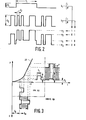
- Fig. 2 die additive Überlagerung des niederratigen und des hochratigen Signals zu einem Summensignal und
- Fig. 3 das mittels eines Lasers erzeugte Sendesignal gemäß der Erfindung.
- 1 is a block diagram of the integrated service digital communication system according to the invention,
- Fig. 2 shows the additive superposition of the low-rate and the high-rate signal to a sum signal and
- Fig. 3 shows the transmission signal generated by a laser according to the invention.
Fig. 1 zeigt als Blockschaltbild das erfindungsgemäße diensteintegrierende, digitale Nachrichtenübertragungssystem mit den zum Verständnis der Erfindung erforderlichen Einrichtungen. Das niederratige Signal bl wird einer Schnittstellenschaltung Sl und das hochratige Signal b2 einer Schnittstellenschaltung S2 zugeführt. Die Ausgangssignale der Schnittstellenschaltungen Sl und S2 werden mit einer vom Bitratenverhältnis abhängigen Gewichtung einander derart überlagert, daß ein in der Amplitude mehrstufiges Summensignal ai entsteht. Diese Form der Überlagerung von zwei Digitalsignalen mit unterschiedlicher Bitrate wird auch als Spektrummultiplex bezeichnet. Durch die additive Verknüpfung in einer Addierstufe A entsteht an dem Ausgang der Addierstufe A ein vierstufiges Summensignal ai, dessen Stufenwerte ai (i= 0..3) den vier möglichen Binärkombinationen des niederratigen Signals bl und des hochratigen Signals b2 zugeordnet sind (vgl. Fig. 2). Die sendeseitige Zusammenfassung des Schmalband- und des Breitbandsignals bl bzw. b2 erfolgt mit einer vom Bitratenverhältnis abhängigen Gewichtung gi gemäß der Gleichung![]()
![]()
Diese Form des Spektrummultiplex führt zu einem modularen Aufbaukonzept, bei dem in einfacher Weise für einen Breitband-Teilnehmeranschluß die übertragungstechnische Ergänzung mit einem Breitbandkanal unter Mitverwendung der für den Schmalband-TeilnehmeranschluB bereits vorhandenen funktionalen Struktur ermöglicht ist. Für den Breitbandkanal, dessen Bitrate wesentlich höher als die der ersten Hierarchiestufe (2Mbit/s) ist, ist im Breitband-Endgerät ebenso wie im Schmalband-Endgerät eine gemeinsame Zugriffssteuerung auf einen Signalisierungskanal gegeben. Im Hinblick auf eine modulare Bedarfsanpassung (Einführungsstrategie), auf eine Notbetriebslösung (Reduktion des Leistungsverbrauch) und auch auf eine die Breitband-Verbindung einleitende Schmalbandverbindung (Dienstwechsel) wird ein Schmalband-Grundbetrieb beim dienstintegrierenden, digitalen Nachrichtenübertragungssystem ermöglicht. Weiterhin ist die Möglichkeit einer durchgängigen Leitungscodierung für das hochratige Signal vom Breitband-Endgerät bis zur Vermittlung (evt. auch durch das Breitband-Koppelfeld hindurch) gegeben.This form of spectrum multiplex leads to a modular design concept, in which the transmission technology can be easily supplemented with a broadband channel for a broadband subscriber line using the functional structure already available for the narrowband subscriber line. For the broadband channel, the bit rate of which is significantly higher than that of the first hierarchical level (2 Mbit / s), common access control to a signaling channel is provided in the broadband terminal as well as in the narrowband terminal. With regard to a modular adaptation of requirements (implementation strategy), an emergency operating solution (reduction in power consumption) and also a narrowband connection that initiates the broadband connection (change of service), narrowband basic operation is made possible in the integrated digital communication system. Furthermore, there is the possibility of a continuous line coding for the high-rate signal from the broadband terminal to the exchange (possibly also through the broadband switching network).
Bei der in Fig. 1 dargestellten Ausführungsform wird im Sender S ein Laser L verwendet, der von einem additiv aus den beiden Signalen bl und b2 gebildeten Strom I angesteuert wird. Weiterhin ist eine Regelung R im Sender S vorgesehen, mittels der zur Arbeitspunkteinstellung des Lasers L eine Vorstrom- und Modulationsstromregelung erfolgt, welche von der Betriebsart abhängige Sollwerte besitzt. Hierfür ist im Sender S eine Betriebs-Überwachung BÜS vorgesehen. Bei einer Veränderung der Steigung in der Laserkennlinie wird, anhand des als Pilotsignals dienenden Schmalbandsignals bl die Verstärkung des Summensignals über die Einrichtung UV derartig geregelt, daß die Amplitudenschwankung Δ P des Sendesignals P konstant bleibt. Eine Verschiebung der Laserkennlinie LK (Fig. 3) in horizontaler Richtung kann mittels einer Einrichtung UI durch Nachregelung des Vorstroms I0, abhängig vom Mittelwert P des Sendesignals P, ausgeglichen werden. Mittels eines im Sender S angeordneten Photodetektors PS werden die Regelgrößen Δ P und P gewonnen.In the embodiment shown in FIG. 1, a laser L is used in the transmitter S, which laser is driven by a current I formed additively from the two signals b 1 and b 2 . Furthermore, a control R is provided in the transmitter S, by means of which a bias current and modulation current control is carried out for setting the operating point of the laser L and which has setpoints which are dependent on the operating mode. For this purpose, an operational monitoring BÜS is provided in the transmitter S. If the slope in the laser characteristic changes, the gain of the sum signal is controlled by means of the device UV on the basis of the narrowband signal b l serving as a pilot signal in such a way that the amplitude fluctuation Δ P of the transmission signal P remains constant. A shift in the laser characteristic curve LK (FIG. 3) in the horizontal direction can be compensated for by means of a device UI by readjusting the bias current I 0 , depending on the mean value P of the transmission signal P. The controlled variables Δ P and P are obtained by means of a photodetector PS arranged in the transmitter S.
Das Ausgangssignal P des Lasers L wird über einen Lichtleiter LL einem Empfänger E zugeführt. Mittels eines am Eingang des Empfängers E angegeordneten Photodetektors PE erfolgt die Umwandlung des optischen Signals in ein elektrisches Summensignal. Zur Trennung des so erzeugten elektrischen Summensignals in das niederratige Signal bl und das hochratige Signal b2 wird dieses einerseits einem, Amplituden-Hüllkurven-Detektor HD und andererseits über einen Verstärker VE1 einem Amplitudenbegrenzer AB zugeführt.The output signal P of the laser L is fed to a receiver E via an optical fiber LL. The optical signal is converted into an electrical sum signal by means of a photodetector PE arranged at the input of the receiver E. To separate the electrical sum signal generated in this way into the low-rate signal b l and the high-rate signal b 2 , the latter is supplied on the one hand to an amplitude envelope detector HD and on the other hand via an amplifier VE1 to an amplitude limiter AB.
Eine derartige Zusammenfassung und Trennung des niederratigen und hochratigen Signals bl, b2 erfordert keine synchrone Taktbeziehung der beiden Signale zueinander und die beiden Signale bl, b2 können mit sich überlappenden Frequenz-Spektren übertragen werden, da die Trennung nicht durch Frequenzselektion sondern durch Amplitudenselektion erfolgt. Für den gemeinsamen Betrieb und für die Übertragung der beiden Signale bl, b2 ist lediglich gefordert, daß die Binärzeichen des hochratigen Signals b2 innerhalb der Schrittdauer des niederratigen Signals b1 statistisch ausgeglichen sind, damit das hochratige Signal b2 als Träger bei der Hüllkurven-Detektion des niederratigen Signals b1 wirkt. Ein hierfür geeigneter binärer Leitungscode für das hochratige Signal b2 ist beispielsweise der CMI-Code.Such a combination and separation of the low-rate and high-rate signals b l , b 2 does not require a synchronous clock relationship of the two signals to one another and the two signals b 1 , b 2 can be transmitted with overlapping frequency spectra, since the separation is not carried out by frequency selection but by amplitude selection. For the common operation and for the transmission of the two signals b l , b 2 , all that is required is that the binary characters of the high-rate signal b 2 are statistically balanced within the step duration of the low-rate signal b 1 , so that the high-rate signal b 2 as a carrier in the Envelope detection of the low-rate signal b 1 acts. A suitable binary line code for the high-rate signal b 2 is, for example, the CMI code.
Weiterhin ist in dem Empfänger E eine Betriebsüberwachung BÜE vorgesehen, mittels der, durch Differenzbildung in der Differenzstufe D des Ausgangssignals des Hüllkurven-Detektors HD und des Ausgangssignals eines den Mittelwert bildenden Tiefpaßfilters TPE, ein den Betriebsfall kennzeichnendes Kriterium für das Vorhandensein des Breitbandsignals b2 ableitbar ist. Die Grenzfrequenz des Tiefpaßfilters TPE entspricht dabei der Nyquistfrequenz des Schmalbandsignals b1.Furthermore, an operational monitoring BÜE is provided in the receiver E, by means of which, by forming a difference in the differential stage D of the output signal of the envelope detector HD and the output signal of a low-pass filter TPE forming the mean value, a criterion characterizing the operating case for the presence of the broadband signal b 2 can be derived is. The cut-off frequency of the low-pass filter TPE corresponds to the Nyquist frequency of the narrowband signal b 1 .
In Fig. 2 ist das bei der Überlagerung der beiden Signale b1 und b2 entstehende vierstufige Summensignal ai im einzelnen dargestellt. Mit ao ist der bei einem optischen Sender einzustellende Vorstrom I0 zu verstehen. Die Amplitudenstufe al entsteht, wenn nur das niederratige Signal b1 vorhanden ist. Die Amplitudenstufe a2 entsteht, wenn nur das hochratige Signal b2 vorhanden ist. Die Amplitudenstufe a3 entsteht, wenn sowohl das niederratige Signal b1 als auch das hochratige Signal b2 vorhanden sind und einander additiv überlagert werden.FIG. 2 shows the four-stage sum signal ai which arises when the two signals b 1 and b 2 are superimposed. Ao is to be understood as the bias current I 0 to be set for an optical transmitter. The amplitude level a l arises when only the low-rate signal b 1 is present. The amplitude level a 2 arises when only the high-rate signal b 2 is present. The amplitude level a 3 arises when both the low-rate signal b 1 and the high-rate signal b 2 are present and are additively superimposed on one another.
Fig. 3 zeigt anhand der Laserkennlinie LK den zeitlichen Verlauf des Laserstroms I und der Laserlichtleistung P im Notbetriebsfall (Betrieb I) und im normalen Betriebsfall (Betrieb II). Im Bereich des Kennlinienknicks der Laserkennlinie LK ist die erzeugte Laserlichtleistung P nichtlinear mit dem Laserstrom I verknüpft. Änderungen in der Laserkennlinie LK lassen sich mittels der bereits erläuterten Regelung R über die Regelgrößen Δ P und P ausgleichen. Die vom Laser L abgegebene modulierte Lichtleistung wird mit der Arbeitspunkteinstellung durch den Vorstrom I0 und durch die Verstärkung des Modulationsstroms Im auf eine für die Übertragung erforderliche mittlere Leistung P für das hochratige Signal b2 und auf eine Spitzenleistungsvariation AP für das niederratige Signal bl geregelt.3 shows the time characteristic of the laser current I and the laser light power P in the emergency operating case (operation I) and in the normal operating case (operation II) on the basis of the laser characteristic curve LK. In the area of the characteristic curve kink of the laser characteristic curve LK, the laser light power P generated is non-linearly linked to the laser current I. Changes in the laser characteristic curve LK can be compensated for by means of the control R already explained using the control variables Δ P and P. The modulated light output emitted by the laser L is regulated with the operating point setting by the bias current I 0 and by the amplification of the modulation current Im to an average power P required for the transmission for the high-rate signal b 2 and to a peak power variation AP for the low-rate signal b l .
Die Überlagerung des niederratigen und des hochratigen Signals b1 und b2 im normalen Betriebsfall ist in Fig. 3 durch den dicken und dünnen Linienzug verdeutlicht.The superimposition of the low-rate and high-rate signals b 1 and b 2 in normal operation is illustrated in FIG. 3 by the thick and thin lines.
Claims (5)
Applications Claiming Priority (2)
| Application Number | Priority Date | Filing Date | Title |
|---|---|---|---|
| DE3544393 | 1985-12-16 | ||
| DE19853544393 DE3544393A1 (en) | 1985-12-16 | 1985-12-16 | SERVICE-INTEGRATING, DIGITAL MESSAGE TRANSMISSION SYSTEM WITH DEVICES FOR THE COMMON TRANSMISSION OF NARROWBAND AND BROADBAND SIGNALS |
Publications (2)
| Publication Number | Publication Date |
|---|---|
| EP0227164A2 true EP0227164A2 (en) | 1987-07-01 |
| EP0227164A3 EP0227164A3 (en) | 1989-03-15 |
Family
ID=6288530
Family Applications (1)
| Application Number | Title | Priority Date | Filing Date |
|---|---|---|---|
| EP86202172A Withdrawn EP0227164A3 (en) | 1985-12-16 | 1986-12-04 | Integrated services digital information transmission system with devices for the simultaneous transmission of broad-band and narrow-band signals |
Country Status (4)
| Country | Link |
|---|---|
| US (1) | US4763326A (en) |
| EP (1) | EP0227164A3 (en) |
| JP (1) | JPS62144431A (en) |
| DE (1) | DE3544393A1 (en) |
Cited By (3)
| Publication number | Priority date | Publication date | Assignee | Title |
|---|---|---|---|---|
| FR2682239A1 (en) * | 1991-10-04 | 1993-04-09 | Cit Alcatel | System for bidirectional transmission, especially by optical fibre, with a single carrier for both transmission directions |
| WO1996029793A2 (en) * | 1995-03-20 | 1996-09-26 | Raychem Corporation | Multiple digital signal multiplexer |
| US6282204B1 (en) | 1997-12-19 | 2001-08-28 | Terayon Communication Systems, Inc. | ISDN plus voice multiplexer system |
Families Citing this family (37)
| Publication number | Priority date | Publication date | Assignee | Title |
|---|---|---|---|---|
| US4933929A (en) * | 1987-06-29 | 1990-06-12 | Nec Corporation | Wavelength multiplexed optical transmitter for generating constant-amplitude angle-modulated beams to eliminate phase noise in adjacent transmission channels |
| US4885747A (en) * | 1988-02-17 | 1989-12-05 | International Business Machines Corp. | Broadband and baseband LAN |
| FR2630871B1 (en) * | 1988-04-29 | 1994-03-18 | Alcatel Cit | METHOD AND DEVICE FOR ADDING AND SEPARATING A LOW-RATE DIGITAL CHANNEL TO THE HIGH-RATE DIGITAL CHANNEL OF A TRANSMISSION LINK |
| JPH0279542A (en) * | 1988-09-14 | 1990-03-20 | Fujitsu Ltd | Subsignal transmission system |
| US5062154A (en) * | 1989-03-03 | 1991-10-29 | The United States Of America As Represented By The Secretary Of The Navy | Mid range UV communications |
| GB8906093D0 (en) * | 1989-03-16 | 1989-04-26 | British Telecomm | Optical transmission system |
| WO1991006161A1 (en) * | 1989-10-13 | 1991-05-02 | Codenoll Technology Corporation | Method and apparatus for simultaneously communicating a plurality of signals |
| US5303229A (en) * | 1991-07-31 | 1994-04-12 | Alcatel Network Systems, Inc. | Optical network unit |
| US5528283A (en) * | 1992-06-22 | 1996-06-18 | Alcatel Network Systems, Inc. | Switched video distribution apparatus |
| US5390185A (en) * | 1992-10-09 | 1995-02-14 | U.S. Philips Corporation | Transmission system for a combination of a main signal and an auxiliary signal |
| DE4341408A1 (en) * | 1993-12-04 | 1995-06-08 | Sel Alcatel Ag | Optical system for the transmission of a multi-stage signal |
| US5499244A (en) * | 1994-05-02 | 1996-03-12 | At&T Corp. | Packet data reciever with sampled data output and background light cancellation |
| DE4438942A1 (en) * | 1994-10-31 | 1996-05-02 | Sel Alcatel Ag | Optical communication system for cable television signals and for subscriber-specific signals |
| US5901151A (en) * | 1996-02-27 | 1999-05-04 | Data General Corporation | System for orthogonal signal multiplexing |
| DE19713952C1 (en) * | 1997-04-04 | 1998-10-15 | Siemens Ag | Method for transmitting additional data signals and a user data signal via optical connections |
| DE19730621A1 (en) | 1997-07-17 | 1999-01-21 | Alsthom Cge Alcatel | Method for transmitting data on an ISDN connection line, as well as line termination unit, switching center, network termination unit and data terminal therefor |
| US6266320B1 (en) * | 1998-04-08 | 2001-07-24 | Telefonaktiebolaget Lm Ericsson (Publ) | Amplitude limitation in CDMA system |
| US6275509B1 (en) | 1998-05-14 | 2001-08-14 | The United States Of America As Represented By The Secretary Of The Navy | Masked signal transceiver |
| WO2001043318A1 (en) * | 1999-12-09 | 2001-06-14 | Photonixnet Kabushiki Kaisha | Optical transmitter/receiver |
| KR100405023B1 (en) * | 2000-12-05 | 2003-11-07 | 옵티시스 주식회사 | Optical communication interface module for universal serial bus |
| US8175020B2 (en) * | 2004-01-30 | 2012-05-08 | Level 3 Communications, Llc | Method for the transmission and distribution of digital television signals |
| US7630631B2 (en) * | 2004-04-14 | 2009-12-08 | Finisar Corporation | Out-of-band data communication between network transceivers |
| EP2134014B1 (en) * | 2008-06-13 | 2010-10-13 | Alcatel Lucent | Method for transmitting two superimposed digital signals and corresponding transmission system |
| WO2013055782A2 (en) | 2011-10-10 | 2013-04-18 | Tyco Electronics Corporation | Broadband radio frequency data communication system using twisted pair wiring |
| JP6141025B2 (en) | 2013-01-15 | 2017-06-07 | 株式会社クボタ | Moor cutter blades and moor |
| JP6437530B2 (en) * | 2013-04-30 | 2018-12-12 | シリコン・ライン・ゲー・エム・ベー・ハー | Circuit apparatus and method for receiving optical signals |
| WO2015038415A1 (en) | 2013-09-13 | 2015-03-19 | Corning Optical Communications LLC | Methods, circuits and optical cable assemblies for optical transmission of high-speed data and low-speed data |
| JP6988604B2 (en) * | 2018-03-16 | 2022-01-05 | 日本電信電話株式会社 | Optical modulation / demodulation method, optical communication system, optical transmitter and receiver |
| US10998982B2 (en) | 2019-04-18 | 2021-05-04 | Microsoft Technology Licensing, Llc | Transmitter for throughput increases for optical communications |
| US10938485B2 (en) | 2019-04-18 | 2021-03-02 | Microsoft Technology Licensing, Llc | Error control coding with dynamic ranges |
| US10873393B2 (en) | 2019-04-18 | 2020-12-22 | Microsoft Technology Licensing, Llc | Receiver training for throughput increases in optical communications |
| US10911155B2 (en) | 2019-04-18 | 2021-02-02 | Microsoft Technology Licensing, Llc | System for throughput increases for optical communications |
| US10911152B2 (en) * | 2019-04-18 | 2021-02-02 | Microsoft Technology Licensing, Llc | Power-based decoding of data received over an optical communication path |
| US10862591B1 (en) | 2019-04-18 | 2020-12-08 | Microsoft Technology Licensing, Llc | Unequal decision regions for throughput increases for optical communications |
| US10897315B2 (en) * | 2019-04-18 | 2021-01-19 | Microsoft Technology Licensing, Llc | Power-based decoding of data received over an optical communication path |
| US11018776B2 (en) | 2019-04-18 | 2021-05-25 | Microsoft Technology Licensing, Llc | Power-based decoding of data received over an optical communication path |
| US10951342B2 (en) | 2019-04-18 | 2021-03-16 | Microsoft Technology Licensing, Llc | Throughput increases for optical communications |
Citations (3)
| Publication number | Priority date | Publication date | Assignee | Title |
|---|---|---|---|---|
| GB1495929A (en) * | 1973-11-24 | 1977-12-21 | British Aircraft Corp Ltd | Communication systems |
| EP0075295A2 (en) * | 1981-09-21 | 1983-03-30 | Siemens Aktiengesellschaft | Optical transmission system for high-frequency digital signals |
| GB2111352A (en) * | 1981-12-01 | 1983-06-29 | Plessey Co Plc | Improvements in or relating to radio communication systems |
Family Cites Families (4)
| Publication number | Priority date | Publication date | Assignee | Title |
|---|---|---|---|---|
| US4328591A (en) * | 1979-04-23 | 1982-05-04 | Baghdady Elie J | Method and apparatus for signal detection, separation and suppression |
| DE2922418C2 (en) * | 1979-06-01 | 1981-12-03 | Licentia Patent-Verwaltungs-Gmbh, 6000 Frankfurt | Integrated services message transmission and switching system for sound, images and data |
| DE3044657A1 (en) * | 1980-11-27 | 1982-07-08 | Licentia Patent-Verwaltungs-Gmbh, 6000 Frankfurt | "SERVICE-INTEGRATED DIGITAL TRANSMISSION SYSTEM" |
| DE3044605A1 (en) * | 1980-11-27 | 1982-06-24 | Licentia Patent-Verwaltungs-Gmbh, 6000 Frankfurt | "SERVICE-INTEGRATED DIGITAL TRANSMISSION SYSTEM" |
-
1985
- 1985-12-16 DE DE19853544393 patent/DE3544393A1/en not_active Withdrawn
-
1986
- 1986-12-03 US US06/937,598 patent/US4763326A/en not_active Expired - Fee Related
- 1986-12-04 EP EP86202172A patent/EP0227164A3/en not_active Withdrawn
- 1986-12-12 JP JP61295133A patent/JPS62144431A/en active Pending
Patent Citations (3)
| Publication number | Priority date | Publication date | Assignee | Title |
|---|---|---|---|---|
| GB1495929A (en) * | 1973-11-24 | 1977-12-21 | British Aircraft Corp Ltd | Communication systems |
| EP0075295A2 (en) * | 1981-09-21 | 1983-03-30 | Siemens Aktiengesellschaft | Optical transmission system for high-frequency digital signals |
| GB2111352A (en) * | 1981-12-01 | 1983-06-29 | Plessey Co Plc | Improvements in or relating to radio communication systems |
Cited By (8)
| Publication number | Priority date | Publication date | Assignee | Title |
|---|---|---|---|---|
| FR2682239A1 (en) * | 1991-10-04 | 1993-04-09 | Cit Alcatel | System for bidirectional transmission, especially by optical fibre, with a single carrier for both transmission directions |
| EP0541409A1 (en) * | 1991-10-04 | 1993-05-12 | Alcatel Cit | Bidirectional transmission system, especially by optical fibre, using a single carrier for both transmission directions |
| US5408350A (en) * | 1991-10-04 | 1995-04-18 | Alcatel Cit | Bidirectional transmission system, especially one using optical fiber, employing a single carrier for both transmission directions |
| WO1996029793A2 (en) * | 1995-03-20 | 1996-09-26 | Raychem Corporation | Multiple digital signal multiplexer |
| WO1996029793A3 (en) * | 1995-03-20 | 1996-11-28 | Raychem Corp | Multiple digital signal multiplexer |
| US5668814A (en) * | 1995-03-20 | 1997-09-16 | Raychem Corporation | Dual DDS data multiplexer |
| US5978390A (en) * | 1995-03-20 | 1999-11-02 | Raychem Corporation | Dual DDS data multiplexer |
| US6282204B1 (en) | 1997-12-19 | 2001-08-28 | Terayon Communication Systems, Inc. | ISDN plus voice multiplexer system |
Also Published As
| Publication number | Publication date |
|---|---|
| EP0227164A3 (en) | 1989-03-15 |
| DE3544393A1 (en) | 1987-06-19 |
| JPS62144431A (en) | 1987-06-27 |
| US4763326A (en) | 1988-08-09 |
Similar Documents
| Publication | Publication Date | Title |
|---|---|---|
| EP0227164A2 (en) | Integrated services digital information transmission system with devices for the simultaneous transmission of broad-band and narrow-band signals | |
| DE69733692T2 (en) | METHOD AND SYSTEM FOR COMPENSATING STAINLESS BITS ASSIGNED TO A RECEIVER OR CODEC | |
| EP0053236B1 (en) | Service-integrated digital transmission system | |
| DE3237168C2 (en) | Telephone system for the transmission of voice and data signals | |
| EP0709978B1 (en) | Optical transmission system for cable television signals and for subscriber signals | |
| DE3990712C2 (en) | Interface unit | |
| EP0386482B1 (en) | Optical data transmission system for subscriber connection | |
| EP0176015B1 (en) | Method for transmitting supplementary information over a digital auxiliary channel and utilisation of the method | |
| EP0386466B1 (en) | Optical information transmission system in the subscriber region | |
| DE3632047C2 (en) | Optical communication system for narrowband and broadband message signals | |
| EP0110464A1 (en) | Private branch exchange | |
| DE2111706C3 (en) | Circuit arrangement for a telephone exchange with pulse phase modulation | |
| DE2056769C3 (en) | Transceiver station in a radio telephone network with selective calling | |
| DE3232599A1 (en) | System for transmission of digital signals | |
| DE4226838B4 (en) | Optical broadband communication system for communication and distribution services | |
| EP0162994A1 (en) | Communication network and its application | |
| EP0126413B1 (en) | Telecommunication system for stream traffic as well as for burst traffic | |
| EP0143268A2 (en) | Process and device for inserting a digital binary narrow-band signal in, or for extracting this norrow-band signal from a time division multiplex signal | |
| AT390857B (en) | CIRCUIT ARRANGEMENT FOR MEDIATING DATA SIGNALS DIFFERENT DATA SIGNAL RATES IN A DATA SWITCHING SYSTEM | |
| EP0990323B1 (en) | Method for optically transmitting signalling and control information in optical wavelength multiplex networks | |
| DE19817007C2 (en) | Process for the use of digital data networks for the purpose of bandwidth reduction in the transmission of data via voice connection paths | |
| WO1999004526A1 (en) | Method for transmitting overhead information for wavelength division multiplex networks for fibre-optic information transmission | |
| EP0135164B1 (en) | Transmission system for higher bit rate digital signals with auxiliary signal transmission | |
| DE19740838A1 (en) | System with discrete variable slot width in TDM / TDMA systems | |
| DE2318800C3 (en) | Messaging system |
Legal Events
| Date | Code | Title | Description |
|---|---|---|---|
| PUAI | Public reference made under article 153(3) epc to a published international application that has entered the european phase |
Free format text: ORIGINAL CODE: 0009012 |
|
| AK | Designated contracting states |
Kind code of ref document: A2 Designated state(s): AT CH DE FR GB IT LI SE |
|
| RAP1 | Party data changed (applicant data changed or rights of an application transferred) |
Owner name: N.V. PHILIPS' GLOEILAMPENFABRIEKEN Owner name: PHILIPS PATENTVERWALTUNG GMBH |
|
| PUAL | Search report despatched |
Free format text: ORIGINAL CODE: 0009013 |
|
| AK | Designated contracting states |
Kind code of ref document: A3 Designated state(s): AT CH DE FR GB IT LI SE |
|
| 17P | Request for examination filed |
Effective date: 19890905 |
|
| 17Q | First examination report despatched |
Effective date: 19910729 |
|
| STAA | Information on the status of an ep patent application or granted ep patent |
Free format text: STATUS: THE APPLICATION IS DEEMED TO BE WITHDRAWN |
|
| 18D | Application deemed to be withdrawn |
Effective date: 19911210 |
|
| RIN1 | Information on inventor provided before grant (corrected) |
Inventor name: KRICK, WOLFGANG, DIPL.-ING. |